transmission ACURA RL KA9 1996 Service Owner's Manual
[x] Cancel search | Manufacturer: ACURA, Model Year: 1996, Model line: RL KA9, Model: ACURA RL KA9 1996Pages: 1954, PDF Size: 61.44 MB
Page 625 of 1954
PCM Memory Setting
NOTE: The PCM reset procedure and disconnecting the
battery or the BACK UP RADIO (7.5 A) fuse cancels the
PCM memory for idle control. The following procedure
is needed after the PCM reset procedure and reconnect-
ing the battery or the BACK UP RADIO (7.5 A) fuse.
1. Start the engine. Hold the engine at 3,000 rpm with
no load (in Park or neutral) until the radiator fan
comes on.
2. Let the engine idle for approx. 5 minutes under the
following conditions:
• Transmission in Park or neutral
• A/C switch OFF
• Headlights OFF
• Rear defogger OFFProCarManuals.com
Page 671 of 1954
The scan tool indicates Diagnostic Trouble Code (DTC) P0420: Insufficient flow in the Exhaust Gas Recirculation
(EGR)
system.
Description
Deterioration (clogging, leakage, etc.) in the EGR line or EGR valve is detected by means of the changes in manifold abso-
lute pressure before and after the operation of the EGR valve.
If deterioration has been detected during two consecutive driving cycles, the MIL will come on and DTC P0401 will be
stored.
Possible Causes
• Clogging, leakage in the EGR line
• Faulty EGR valve
Troubleshooting Flowchart
Is DTC P0401 indicated?
Intermittent failure, system is OK
at this time.
YES
Clean the intake manifold EGR
port and EGR passage with car-
buretor cleaner.
Clean the passage inside the
EGR valve with carburetor
cleaner or replace the valve.
NO
Problem verification:
1. Do the PCM Reset Procedure.
2. Connect the ACS service con-
nector.
3. Test-drive under the following
conditions.
— Without any electrical load
— Transmission in posi-
tion
— Decelerate from 55 mph
(88 km/h) for at least 5 sec-
onds.
The MIL has been reported on.
DTC P0401 is stored.ProCarManuals.com
Page 712 of 1954
Description
The automatic transmission is a combination of a 3-element torque converter and a dual-shaft electronically controlled
automatic transmission which provides 4 speeds forward and 1 reverse. The entire unit is positioned in line with the engine.
Torque Converter, Gears and Clutches
The torque converter consists of a pump, turbine and stator, assembled in a single unit. They are connected to the engine
crankshaft so they turn together as a unit as the engine turns. Around the outside of the drive plate is a ring gear which
meshes with the starter pinion when the engine is being started.
The entire torque converter assembly serves as a flywheel while transmitting power to the transmission mainshaft.
The transmission has two parallel shafts: the mainshaft and the countershaft. The mainshaft is in line with the engine
crankshaft. The mainshaft includes the 1st, 4th and 2nd clutches and gears for 4th, 1st, 2nd and reverse (3rd gear is integral
with the mainshaft). The countershaft includes the 3rd, 1st-hold and reverse clutches, and gears for 3rd, 4th, 1st, 2nd,
reverse and park. The secondary drive gear is integrated with the countershaft. The gears on the mainshaft are in constant
mesh with those on the countershaft. When certain combinations of gears in the transmission are engaged by clutches,
power is transmitted from the mainshaft to the countershaft to provide , , , and positions.
Electronic Control
The electronic control system consists of a Powertrain Control Module (PCM), sensors, a A/T clutch pressure control solenoid
and four solenoid valves. Shifting and lock-up are electronically controlled for comfortable driving under all conditions.
The PCM is located below the dashboard, under the front lower panel on the passenger's side.
Hydraulic Control
The lower valve body assembly includes the main valve body, the secondary valve body, the throttle valve body, the
solenoid, the shift solenoid valves and the ATF passage body. They are bolted on the lower part of the transmission hous-
ing. Other valve bodies, the regulator valve body, the ATF pump body and the accumulator body, are bolted to the torque
converter housing.
The main valve body contains the manual valve, the 1-2 shift valve, the 2-3 shift valve, the 3-4 shift valve, the 4-3 kick-down
valve and the main orifice control valve. The secondary valve body contains the 3-4 orifice control valve, the 4-3 shift timing
valve, the line pressure control valve, the modulator valve and the accumulator pistons. The throttle valve body includes
the throttle valve which is bolted onto the secondary valve body. The A/T clutch pressure control solenoid is joined to the
throttle valve body. The regulator valve body contains the regulator valve, the lock-up shift valve and the cooler relief valve.
Fluid from the regulator passes through the manual valve to the various control valves. The ATF pump body contains the
lock-up timing valve, the lock-up control valve and the relief valve. The torque converter check valve is located in the torque
converter housing under the ATF pump body. The accumulator body contains the accumulator pistons. The reverse accu-
mulator and the 1st-hold accumulator pistons are assembled in the rear cover.
The 1st, 1st-hold, 2nd and reverse clutches receive fluid from their respective feed pipes, and the 3rd and 4th clutches
receive fluid from the internal hydraulic circuit.
Shift Control Mechanism
Input from various sensors located throughout the vehicle determines which shift solenoid valve the PCM will activate.
Activating a shift solenoid valve changes modulator pressure, causing a shift valve to move. This pressurizes a line to one
of the clutches, engaging the clutch and its corresponding gear.
Lock-up Mechanism
In position, in 2nd, 3rd, and 4th, and position in 3rd, pressurized fluid is drained from the back of the torque con-
verter through a fluid passage, causing the lock-up piston to be held against the torque converter cover. As this takes
place, the mainshaft rotates at the same speed as the engine crankshaft. Together with hydraulic control, the PCM opti-
mizes the timing of the lock-up mechanism. The lock-up valves control the range of lock-up according to torque converter
clutch (lock-up control) solenoid valves A and B, and throttle valve. When torque converter clutch (lock-up control)
solenoid valves A and B activate, modulator pressure changes. The torque converter clutch (lock-up control) solenoid
valves A and B are mounted on the torque converter housing, and are controlled by the PCM.ProCarManuals.com
Page 731 of 1954
Description
Electronic Control System (cont'd)
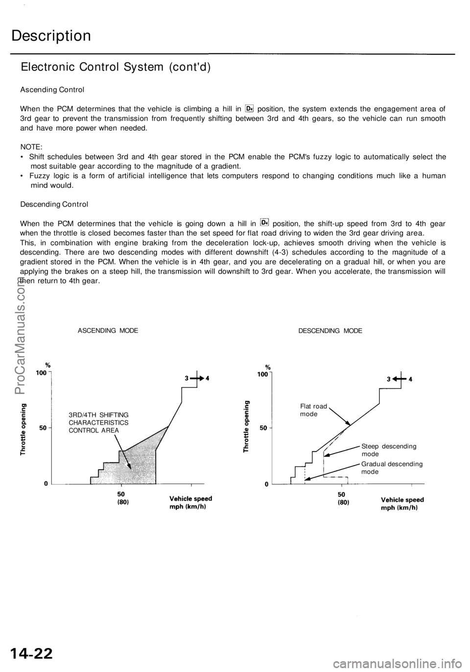
Ascending Control
When the PCM determines that the vehicle is climbing a hill in position, the system extends the engagement area of
3rd gear to prevent the transmission from frequently shifting between 3rd and 4th gears, so the vehicle can run smooth
and have more power when needed.
NOTE:
• Shift schedules between 3rd and 4th gear stored in the PCM enable the PCM's fuzzy logic to automatically select the
most suitable gear according to the magnitude of a gradient.
• Fuzzy logic is a form of artificial intelligence that lets computers respond to changing conditions much like a human
mind would.
Descending Control
When the PCM determines that the vehicle is going down a hill in position, the shift-up speed from 3rd to 4th gear
when the throttle is closed becomes faster than the set speed for flat road driving to widen the 3rd gear driving area.
This, in combination with engine braking from the deceleration lock-up, achieves smooth driving when the vehicle is
descending. There are two descending modes with different downshift (4-3) schedules according to the magnitude of a
gradient stored in the PCM. When the vehicle is in 4th gear, and you are decelerating on a gradual hill, or when you are
applying the brakes on a steep hill, the transmission will downshift to 3rd gear. When you accelerate, the transmission will
then return to 4th gear.
ASCENDING MODE
DESCENDING MODE
3RD/4TH SHIFTING
CHARACTERISTICS
CONTROL AREA
Flat road
mode
Steep descending
mode
Gradual descending
modeProCarManuals.com
Page 734 of 1954
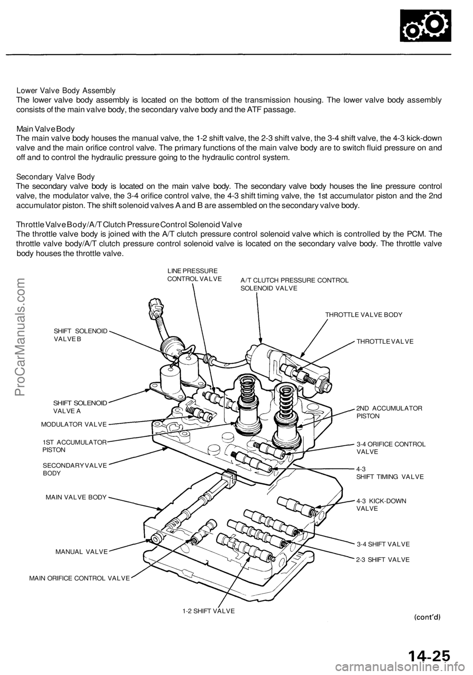
Lower Valve Body Assembly
The lower valve body assembly is located on the bottom of the transmission housing. The lower valve body assembly
consists of the main valve body, the secondary valve body and the ATF passage.
Main Valve Body
The main valve body houses the manual valve, the 1-2 shift valve, the 2-3 shift valve, the 3-4 shift valve, the 4-3 kick-down
valve and the main orifice control valve. The primary functions of the main valve body are to switch fluid pressure on and
off and to control the hydraulic pressure going to the hydraulic control system.
Secondary Valve Body
The secondary valve body is located on the main valve body. The secondary valve body houses the line pressure control
valve, the modulator valve, the 3-4 orifice control valve, the 4-3 shift timing valve, the 1st accumulator piston and the 2nd
accumulator piston. The shift solenoid valves A and B are assembled on the secondary valve body.
Throttle Valve Body/A/T Clutch Pressure Control Solenoid Valve
The throttle valve body is joined with the A/T clutch pressure control solenoid valve which is controlled by the PCM. The
throttle valve body/A/T clutch pressure control solenoid valve is located on the secondary valve body. The throttle valve
body houses the throttle valve.
LINE PRESSURE
CONTROL VALVE
A/T CLUTCH PRESSURE CONTROL
SOLENOID VALVE
SHIFT SOLENOID
VALVE B
SHIFT SOLENOID
VALVE A
MODULATOR VALVE
1ST ACCUMULATOR
PISTON
SECONDARY VALVE
BODY
MAIN VALVE BODY
MANUAL VALVE
MAIN ORIFICE CONTROL VALVE
THROTTLE VALVE BODY
THROTTLE VALVE
2ND ACCUMULATOR
PISTON
3-4 ORIFICE CONTROL
VALVE
4-3
SHIFT TIMING VALVE
4-3 KICK-DOWN
VALVE
3-4 SHIFT VALVE
2-3 SHIFT VALVE
1-2 SHIFT VALVEProCarManuals.com
Page 738 of 1954
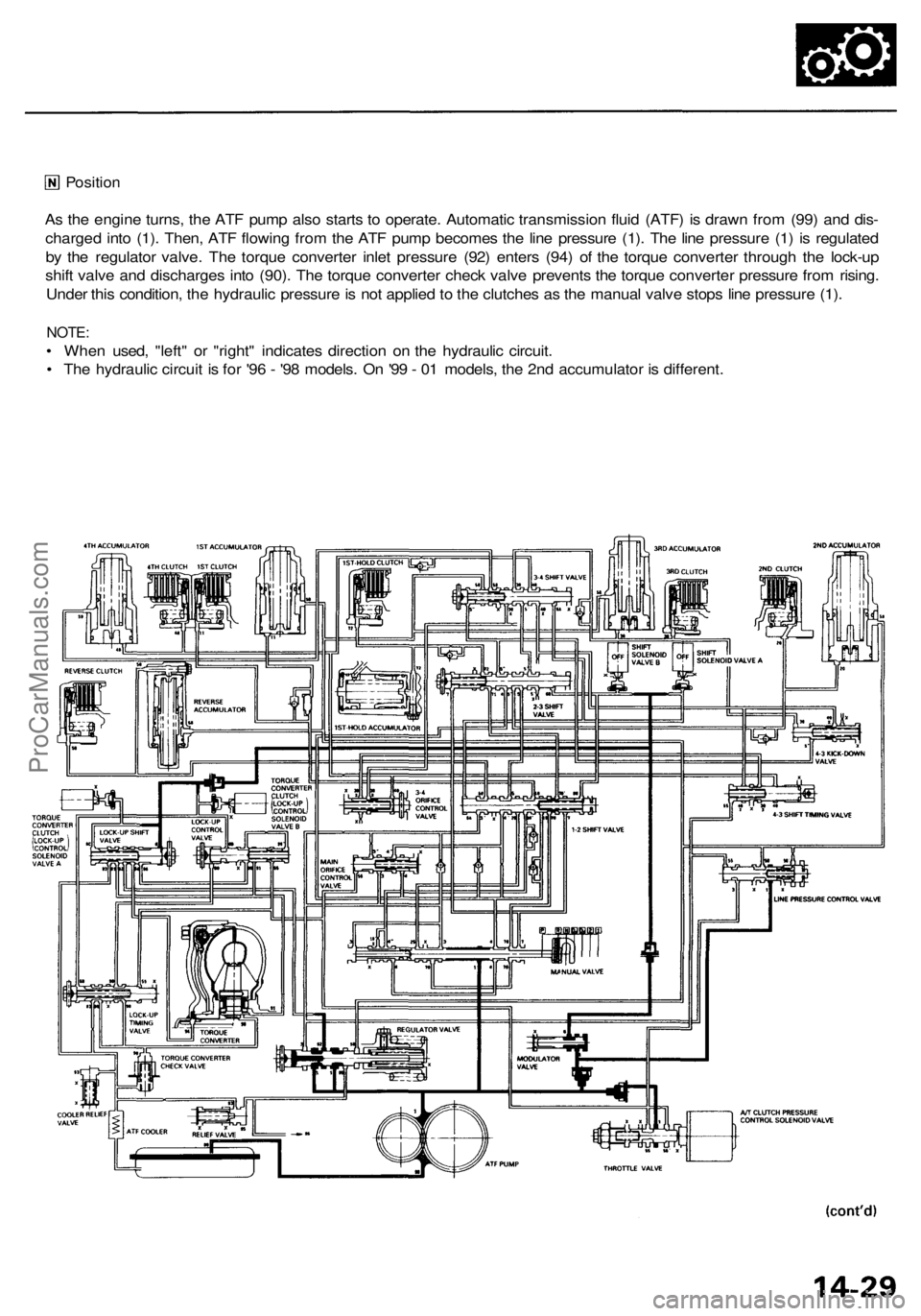
Position
As the engine turns, the ATF pump also starts to operate. Automatic transmission fluid (ATF) is drawn from (99) and dis-
charged into (1). Then, ATF flowing from the ATF pump becomes the line pressure (1). The line pressure (1) is regulated
by the regulator valve. The torque converter inlet pressure (92) enters (94) of the torque converter through the lock-up
shift valve and discharges into (90). The torque converter check valve prevents the torque converter pressure from rising.
Under this condition, the hydraulic pressure is not applied to the clutches as the manual valve stops line pressure (1).
NOTE:
• When used, "left" or "right" indicates direction on the hydraulic circuit.
• The hydraulic circuit is for '96 - '98 models. On '99 - 01 models, the 2nd accumulator is different.ProCarManuals.com
Page 754 of 1954
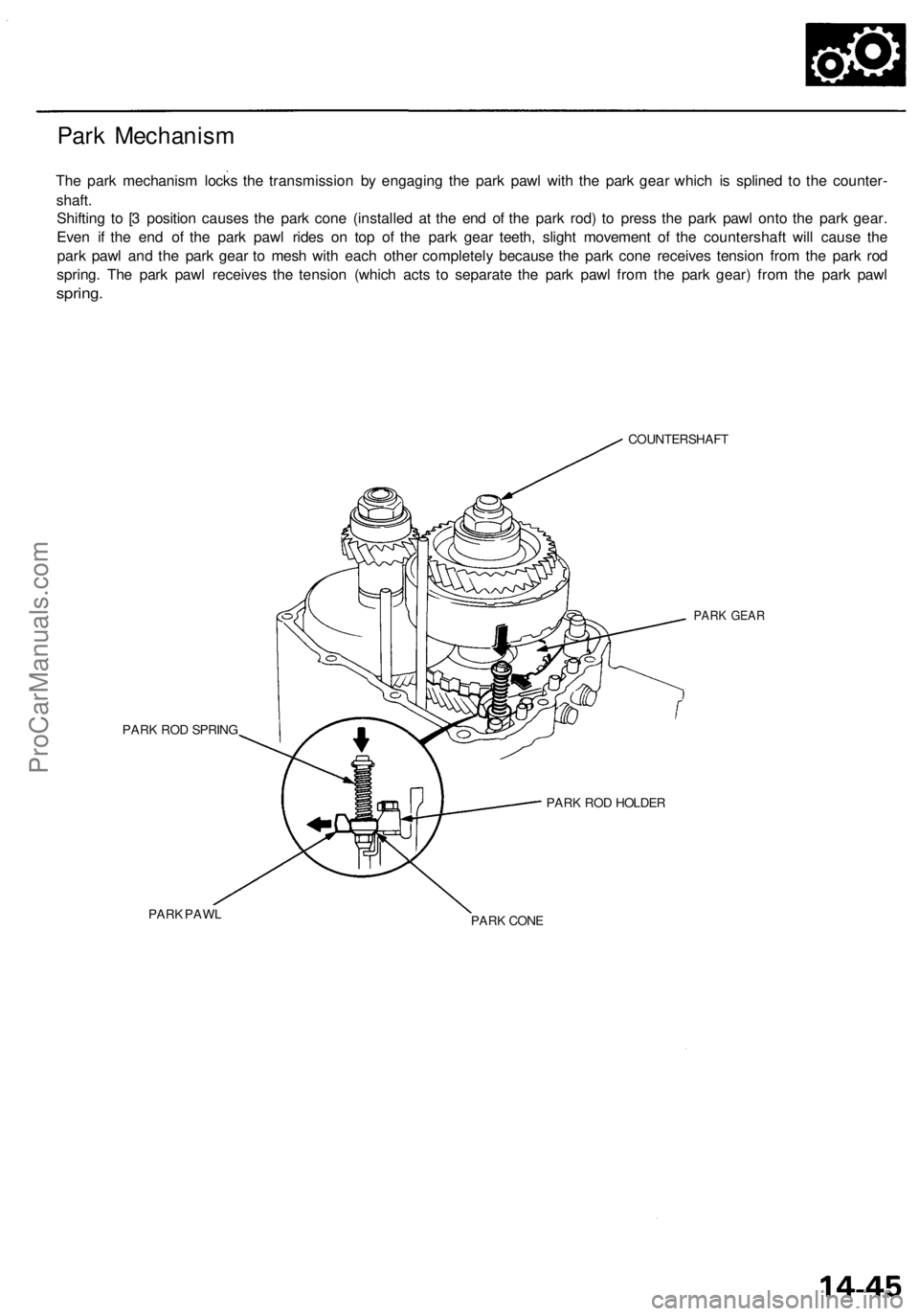
Park Mechanism
The park mechanism locks the transmission by engaging the park pawl with the park gear which is splined to the counter-
shaft.
Shifting to [3 position causes the park cone (installed at the end of the park rod) to press the park pawl onto the park gear.
Even if the end of the park pawl rides on top of the park gear teeth, slight movement of the countershaft will cause the
park pawl and the park gear to mesh with each other completely because the park cone receives tension from the park rod
spring. The park pawl receives the tension (which acts to separate the park pawl from the park gear) from the park pawl
spring.
COUNTERSHAFT
PARK ROD SPRING
PARK PAWL
PARK GEAR
PARK ROD HOLDER
PARK CONEProCarManuals.com
Page 758 of 1954
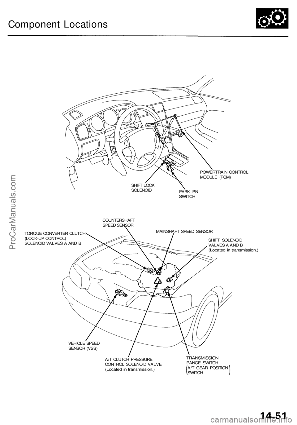
Component Locations
POWERTRAIN CONTROL
MODULE (PCM)
SHIFT LOCK
SOLENOID
PARK PIN
SWITCH
COUNTERSHAFT
SPEED SENSOR
TORQUE CONVERTER CLUTCH
(LOCK-UP CONTROL)
SOLENOID VALVES A AND B
MAINSHAFT SPEED SENSOR
SHIFT SOLENOID
VALVES A AND B
(Located in transmission.)
VEHICLE SPEED
SENSOR (VSS)
A/T CLUTCH PRESSURE
CONTROL SOLENOID VALVE
(Located in transmission.)
TRANSMISSION
RANGE SWITCH
A/T GEAR POSITION
SWITCHProCarManuals.com
Page 776 of 1954
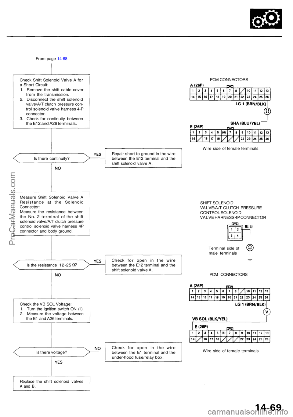
From pag e 14-6 8
Chec k Shif t Solenoi d Valv e A fo r
a Shor t Circuit :
1 . Remov e th e shif t cabl e cove r
fro m th e transmission .
2. Disconnec t th e shif t solenoi dvalve/A/ T clutc h pressur e con -
tro l solenoi d valv e harnes s 4- P
connector .
3. Chec k fo r continuit y betwee nthe E1 2 an d A2 6 terminals .
Is ther e continuity ?
Measur e Shif t Solenoi d Valv e A
Resistanc e a t th e Solenoi d
Connector :
Measur e th e resistanc e betwee n
the No . 2 termina l o f th e shif tsolenoi d valve/A/ T clutc h pressur e
contro l solenoi d valv e harnes s 4 P
connecto r an d bod y ground .
Is th e resistanc e 12-2 5
Chec k th e V B SO L Voltage :
1 . Tur n th e ignitio n switc h O N (II) .
2 . Measur e th e voltag e betwee n
th e E 1 an d A2 6 terminals .
I s ther e voltage ? Repai
r shor t t o groun d in th e wir e
betwee n th e E1 2 termina l an d th e
shif t solenoi d valv e A .
Chec k fo r ope n i n th e wir e
betwee n th e E1 2 termina l an d th e
shif t solenoi d valv e A .
Chec k fo r ope n i n th e wir e
betwee n th e E 1 termina l an d th e
under-hoo d fuse/rela y box . PC
M CONNECTOR S
Wir e sid e o f femal e terminal s
SHIF T SOLENOI D
VALVE/A/ T CLUTC H PRESSUR E
CONTRO L SOLENOI D
VALV E HARNES S 4P CONNECTO R
Termina l sid e o f
mal e terminal s
PC M CONNECTOR S
Wir e sid e o f femal e terminal s
Replac e th e shif t solenoi d valve s
A an d B .
ProCarManuals.com
Page 778 of 1954
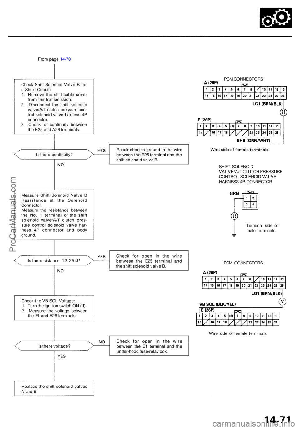
From pag e 14-7 0
Chec k Shif t Solenoi d Valv e B fo r
a Shor t Circuit :
1 . Remov e th e shif t cabl e cove r
fro m th e transmission .
2 . Disconnec t th e shif t solenoi d
valve/A/ T clutc h pressur e con -
tro l solenoi d valv e harnes s 4 P
connector .
3 . Chec k fo r continuit y betwee n
th e E2 5 an d A2 6 terminals .
I s ther e continuity ?
Measur e Shif t Solenoi d Valv e B
Resistanc e a t th e Solenoi d
Connector :
Measur e th e resistanc e betwee n
th e No . 1 termina l o f th e shif t
solenoi d valve/A/ T clutc h pres -
sur e contro l solenoi d valv e har -
nes s 4 P connecto r an d bod y
ground .
Is th e resistanc e 12-2 5
Replac e th e shif t solenoi d valve s
A an d B .
Repai r shor t t o groun d in th e wir ebetwee n th e E2 5 termina l an d th eshif t solenoi d valv e B .
Chec k fo r ope n i n th e wir e
betwee n th e E2 5 termina l an d
th e shif t solenoi d valv e B .
Chec k fo r ope n i n th e wir e
betwee n th e E 1 termina l an d th e
under-hoo d fuse/rela y box . PC
M CONNECTOR S
SHIF T SOLENOI D
VALVE/A/ T CLUTC H PRESSUR E
CONTRO L SOLENOI D VALV E
HARNES S 4 P CONNECTO R
Termina l sid e o f
mal e terminal s
PC M CONNECTOR S
Wir e sid e o f femal e terminal s
Chec
k th e V B SO L Voltage :
1. Tur n th e ignitio n switc h O N (II) .2. Measur e th e voltag e betwee n
th e E l an d A2 6 terminals .
I s ther e voltage ?
ProCarManuals.com