charging ACURA RL KA9 1996 Service Repair Manual
[x] Cancel search | Manufacturer: ACURA, Model Year: 1996, Model line: RL KA9, Model: ACURA RL KA9 1996Pages: 1954, PDF Size: 61.44 MB
Page 343 of 1954
Charging Syste m
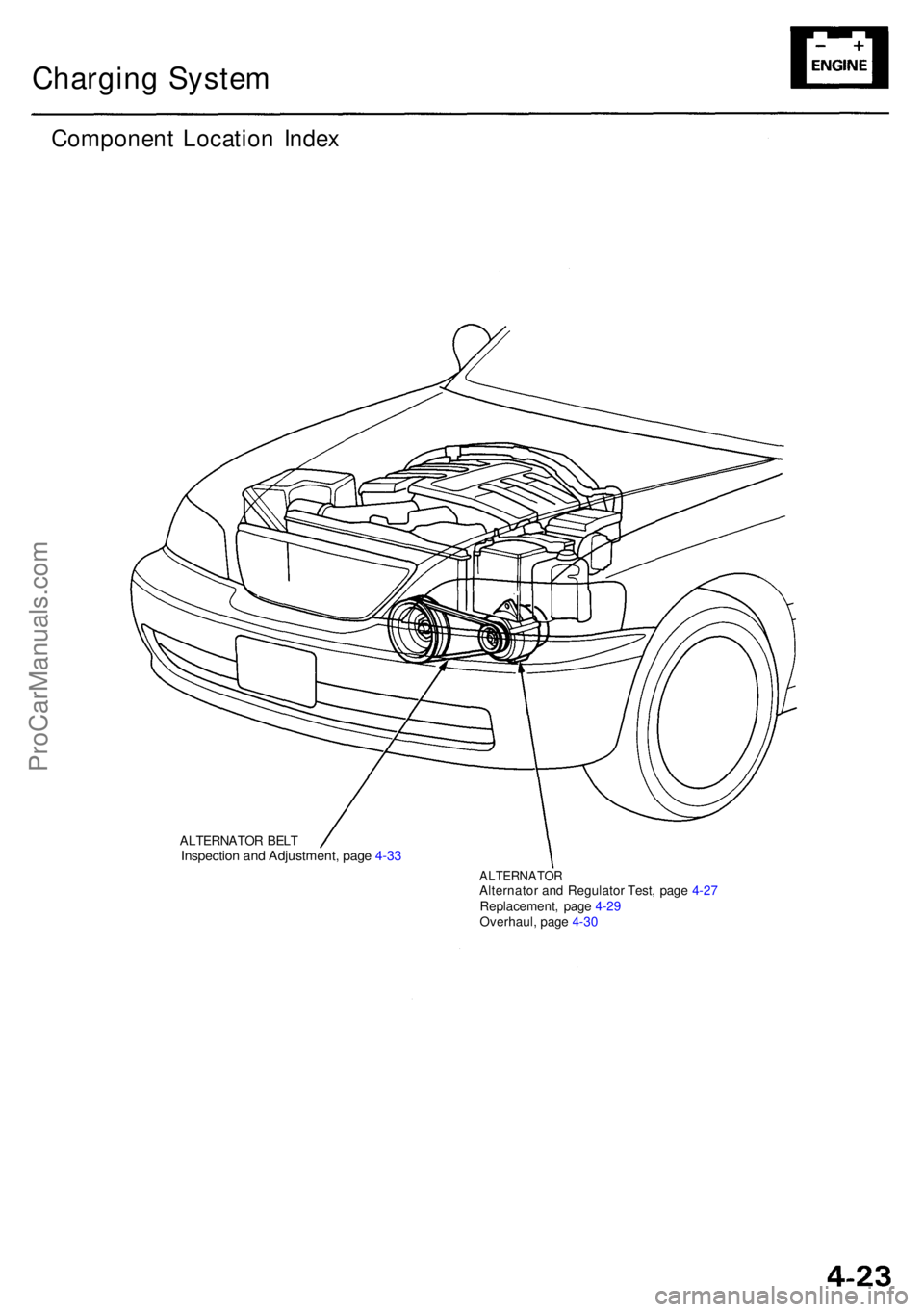
Componen t Locatio n Inde x
ALTERNATO R BEL TInspectio n an d Adjustment , pag e 4-3 3
ALTERNATO RAlternator an d Regulato r Test , pag e 4-2 7
Replacement , pag e 4-2 9
Overhaul , pag e 4-3 0
ProCarManuals.com
Page 345 of 1954
Charging Syste m
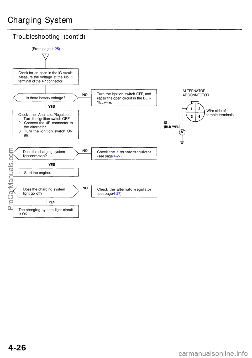
Troubleshootin g (cont'd )
(From page 4-25)
Chec k fo r a n ope n in th e IG circuit :
Measur e th e voltag e a t th e No . 1
termina l o f th e 4 P connector .
I s ther e batter y voltage ?
Chec k th e Alternator/Regulator :
1. Tur n th e ignitio n switc h OFF .2. Connec t th e 4 P connecto r t o
th e alternator .
3. Tur n th e ignitio n switc h O N(II).
Doe s th e chargin g syste mlight com e on ?
4. Star t th e engine .
Doe s th e chargin g syste m
ligh t g o off ?
Th e chargin g syste m ligh t circui t
is OK .
Turn th e ignitio n switc h OFF , an drepai r th e ope n circui t i n th e BLK /YEL wire .
ALTERNATO R4P CONNECTO R
Wir e sid e o f
femal e terminal s
Check th e alternator/regulato r
(se e pag e 4-27 ).
Chec k th e alternator/regulato r
(se e pag e 4-27 ).
ProCarManuals.com
Page 347 of 1954
Charging Syste m
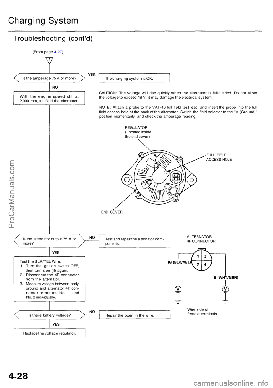
Troubleshootin g (cont'd )
(From page 4-27)
I s th e amperag e 7 5 A or more ?
The chargin g syste m is OK .
Wit h th e engin e spee d stil l a t2,00 0 rpm , full-fiel d th e alternator. CAUTION
: Th e voltag e wil l ris e quickl y whe n th e alternato r i s full-fielded . D o no t allo w
th e voltag e to excee d 1 8 V ; i t ma y damag e th e electrica l system .
NOTE : Attac h a prob e t o th e VAT-4 0 ful l fiel d tes t lead , an d inser t th e prob e int o th e ful l
fiel d acces s hol e a t th e bac k o f th e alternator . Switc h th e fiel d selecto r t o th e " A (Ground) "
positio n momentarily , an d chec k th e amperag e reading .
REGULATO R(Located insid e
th e en d cover )
FULL FIEL DACCES S HOL E
END COVE R
Is th e alternato r outpu t 7 5 A ormore ?Test an d repai r th e alternato r com -ponents .
ALTERNATO R4P CONNECTO R
Tes t th e BLK/YE L Wire :
1 . Tur n th e ignitio n switc h OFF ,
the n tur n i t o n (II ) again .
2 . Disconnec t th e 4 P connecto r
fro m th e alternator .
3. Measur e voltag e betwee n bod ygroun d an d alternato r 4 P con -
necto r terminal s No . 1 an d
No. 2 individually .
Is ther e batter y voltage ?
Repair th e ope n in th e wire . Wir
e sid e o ffemal e terminal s
Replace th e voltag e regulator .
ProCarManuals.com
Page 349 of 1954
Charging Syste m
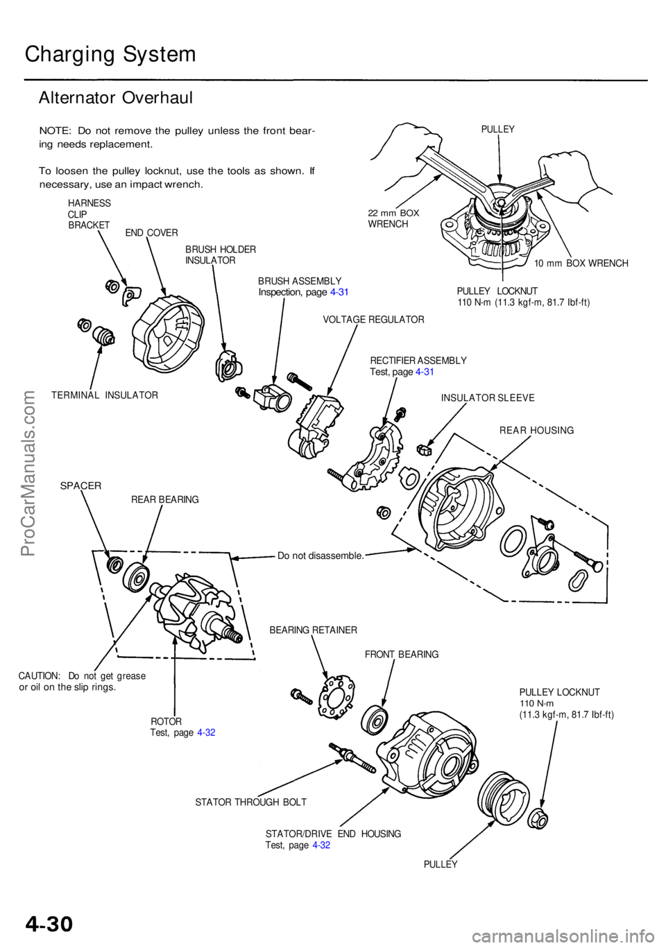
Alternato r Overhau l
NOTE: D o no t remov e th e pulle y unles s th e fron t bear -
in g need s replacement .
T o loose n th e pulle y locknut , us e th e tool s a s shown . I f
necessary , us e a n impac t wrench .
HARNES S
CLI P
BRACKE T
PULLEY
END COVE R
BRUS H HOLDE R
INSULATO R
BRUSH ASSEMBL Y
Inspection, pag e 4-3 1
22 m m BO XWRENC H
10 m m BO X WRENC H
PULLE Y LOCKNU T
11 0 N- m (11. 3 kgf-m , 81. 7 Ibf-ft )
VOLTAG E REGULATO R
RECTIFIE R ASSEMBL Y
Test, pag e 4-3 1
TERMINA L INSULATO R
INSULATOR SLEEV E
REA R HOUSIN G
SPACER
CAUTION : D o no t ge t greas eor oi l o n th e sli p rings .
ROTO RTest, pag e 4-3 2 PULLE
Y LOCKNU T
110 N- m(11. 3 kgf-m , 81. 7 Ibf-ft )
STATO R THROUG H BOL T
STATOR/DRIV E EN D HOUSIN G
Test , pag e 4-3 2
PULLE Y
FRONT BEARIN G
BEARIN
G RETAINE R
Do no t disassemble .
REAR BEARIN G
ProCarManuals.com
Page 351 of 1954
Charging System
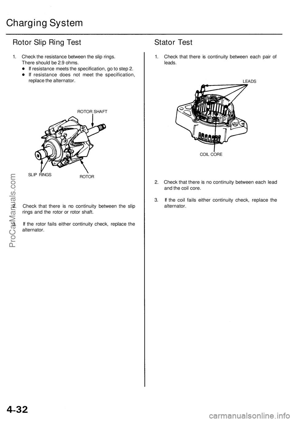
Rotor Slip Ring Test
1. Check the resistance between the slip rings.
There should be 2.9 ohms.
If resistance meets the specification, go to step 2.
If resistance does not meet the specification,
replace the alternator.
ROTOR SHAFT
SLIP RINGS
ROTOR
2. Check that there is no continuity between the slip
rings and the rotor or rotor shaft.
3. If the rotor fails either continuity check, replace the
alternator.
Stator Test
1. Check that there is continuity between each pair of
leads.
LEADS
COIL CORE
2. Check that there is no continuity between each lead
and the coil core.
3. If the coil fails either continuity check, replace the
alternator.ProCarManuals.com
Page 353 of 1954
Charging Syste m
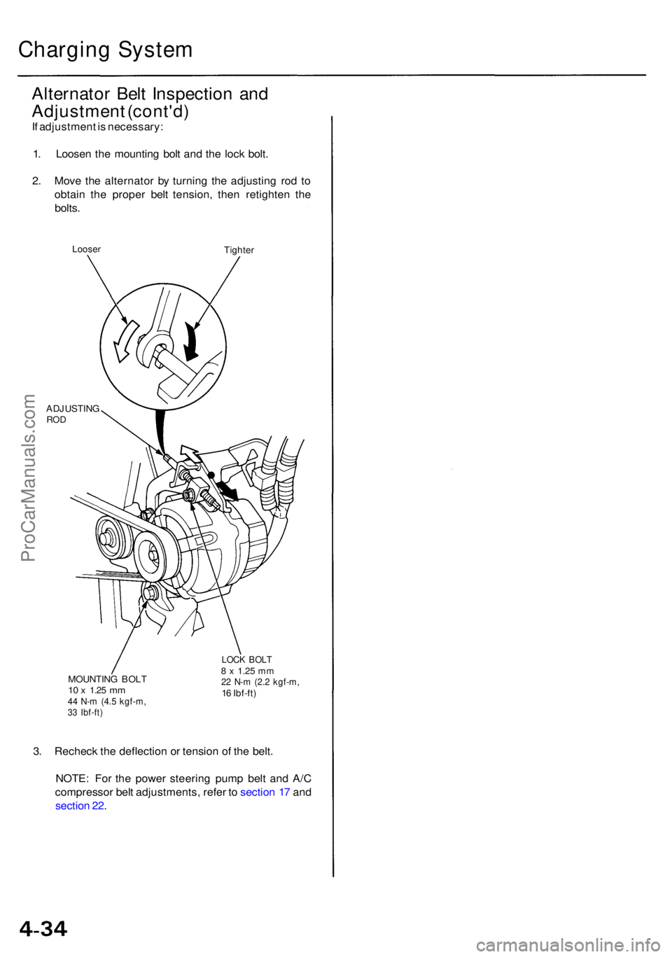
Alternato r Bel t Inspectio n an d
Adjustmen t (cont'd )
If adjustmen t i s necessary :
1 . Loose n th e mountin g bol t an d th e loc k bolt .
2 . Mov e th e alternato r b y turnin g th e adjustin g ro d t o
obtai n th e prope r bel t tension , the n retighte n th e
bolts .
Loose rTighte r
ADJUSTIN G
ROD
MOUNTIN G BOL T10 x 1.2 5 mm44 N- m (4. 5 kgf-m ,33 Ibf-ft )
LOCK BOL T8 x 1.2 5 mm22 N- m (2. 2 kgf-m ,16 Ibf-ft )
3. Rechec k th e deflectio n o r tensio n o f th e belt .
NOTE : Fo r th e powe r steerin g pum p bel t an d A/ C
compresso r bel t adjustments , refe r t o sectio n 1 7 an d
sectio n 22 .
ProCarManuals.com
Page 558 of 1954
PGM-FI Syste m
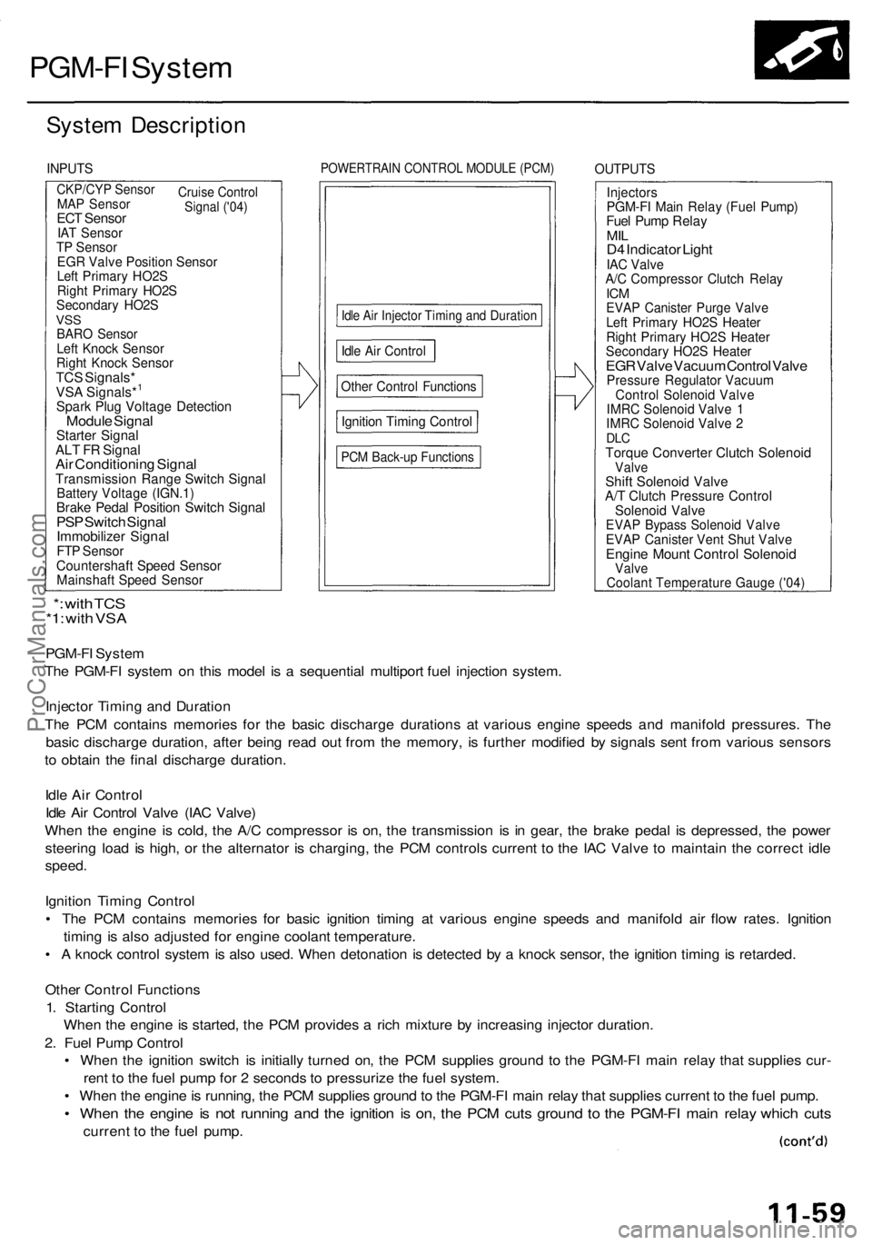
System Descriptio n
INPUTSPOWERTRAI N CONTRO L MODUL E (PCM )OUTPUT S
CKP/CYP Senso r
Cruise
Control
Signal ('04)MA P Senso rECT Senso rIAT Senso rTP Senso rEGR Valv e Positio n Senso rLeft Primar y HO2 SRight Primar y HO2 SSecondar y HO2 SVSSBAR O Senso rLeft Knoc k Senso rRight Knoc k Senso rTCS Signals *VSA Signals*1
Spar k Plu g Voltag e Detectio nModule Signa lStarte r Signa lALT F R Signa lAir Conditionin g Signa lTransmissio n Rang e Switc h Signa lBattery Voltag e (IGN.1 )Brake Peda l Positio n Switc h Signa lPSP Switc h Signa lImmobilize r Signa lFTP Senso rCountershaf t Spee d Senso rMainshaf t Spee d Senso r
Idle Ai r Injecto r Timin g an d Duratio n
Other Contro l Function s
Ignition Timin g Contro l
PCM Back-u p Function s
InjectorsPGM-FI Mai n Rela y (Fue l Pump )Fuel Pum p Rela yMILD4 Indicato r Ligh tIAC Valv eA/C Compresso r Clutc h Rela yICMEVA P Caniste r Purg e Valv eLeft Primar y HO2 S Heate rRight Primar y HO2 S Heate rSecondar y HO2 S Heate rEGR Valv e Vacuu m Contro l Valv ePressur e Regulato r Vacuu mControl Solenoi d Valv eIMRC Solenoi d Valv e 1IMR C Solenoi d Valv e 2DL CTorqu e Converte r Clutc h Solenoi dValveShift Solenoi d Valv eA/T Clutc h Pressur e Contro lSolenoid Valv eEVAP Bypas s Solenoi d Valv eEVAP Caniste r Ven t Shu t Valv eEngin e Moun t Contro l Solenoi dValve
PGM-F I Syste m
Th e PGM-F I syste m o n thi s mode l i s a sequentia l multipor t fue l injectio n system .
Injecto r Timin g an d Duratio n
Th e PC M contain s memorie s fo r th e basi c discharg e duration s a t variou s engin e speed s an d manifol d pressures . Th e
basi c discharg e duration , afte r bein g rea d ou t fro m th e memory , i s furthe r modifie d b y signal s sen t fro m variou s sensor s
t o obtai n th e fina l discharg e duration .
Idl e Ai r Contro l
Idl e Ai r Contro l Valv e (IA C Valve )
Whe n th e engin e i s cold , th e A/ C compresso r i s on , th e transmissio n i s i n gear , th e brak e peda l i s depressed , th e powe r
steerin g loa d i s high , o r th e alternato r i s charging , th e PC M control s curren t t o th e IA C Valv e t o maintai n th e correc t idl e
speed .
Ignition Timin g Contro l
• Th e PC M contain s memorie s fo r basi c ignitio n timin g a t variou s engin e speed s an d manifol d ai r flo w rates . Ignitio n
timin g i s als o adjuste d fo r engin e coolan t temperature .
• A knoc k contro l syste m is als o used . Whe n detonatio n i s detecte d b y a knoc k sensor , th e ignitio n timin g is retarded .
Othe r Contro l Function s
1 . Startin g Contro l
Whe n th e engin e is started , th e PC M provide s a ric h mixtur e b y increasin g injecto r duration .
2 . Fue l Pum p Contro l
• Whe n th e ignitio n switc h i s initiall y turne d on , th e PC M supplie s groun d t o th e PGM-F I mai n rela y tha t supplie s cur -
ren t t o th e fue l pum p fo r 2 second s t o pressuriz e th e fue l system .
• Whe n th e engin e is running , th e PC M supplie s groun d to th e PGM-F I mai n rela y tha t supplie s current to th e fue l pump .
• Whe n th e engin e is no t runnin g an d th e ignitio n i s on , th e PC M cut s groun d t o th e PGM-F I mai n rela y whic h cut s
curren t t o th e fue l pump .
*: wit h TC S*1: wit h VS A
Idle Ai r Contro l
Coolant Temperature Gauge ('04)
ProCarManuals.com
Page 617 of 1954
Idle Contro l Syste m
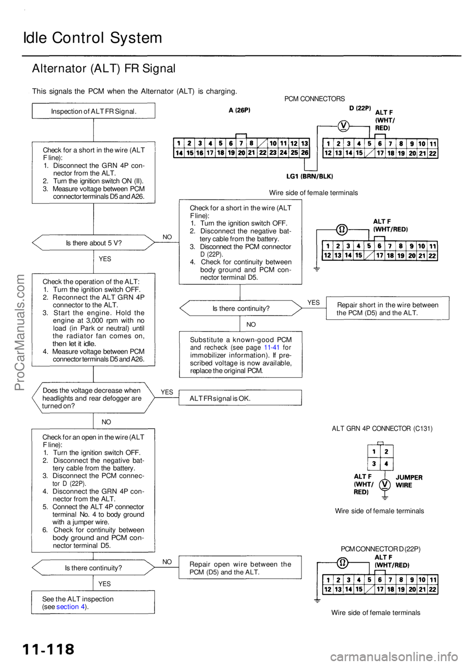
Alternato r (ALT ) F R Signa l
PCM CONNECTOR S
Is ther e abou t 5 V ?
YE S
Chec k th e operatio n o f th e ALT :
1 . Tur n th e ignitio n switc h OFF .
2 . Reconnec t th e AL T GR N 4 P
connecto r t o th e ALT .
3 . Star t th e engine . Hol d th e
engin e a t 3,00 0 rp m wit h n o
loa d (i n Par k o r neutral ) unti l
th e radiato r fa n come s on ,
then le t i t idle .4. Measur e voltag e betwee n PC M
connecto r terminal s D 5 an d A26 .
Doe s th e voltag e decreas e whe n
headlight s an d rea r defogge r ar e
turne d on ?
NO
Chec k fo r a n ope n in th e wir e (AL T
F line) :
1 . Tur n th e ignitio n switc h OFF .
2 . Disconnec t th e negativ e bat -
ter y cabl e fro m th e battery .
3 . Disconnec t th e PC M connec -
tor D (22P) .4. Disconnec t th e GR N 4 P con -
necto r fro m th e ALT .
5 . Connec t th e AL T 4 P connecto r
termina l No . 4 to bod y groun d
wit h a jumpe r wire .
6 . Chec k fo r continuit y betwee n
body groun d an d PC M con -necto r termina l D5 .
I s ther e continuity ?
YES
See th e AL T inspectio n
(see sectio n 4 ).
N O
Wir e sid e o f femal e terminal s
Chec k fo r a shor t i n th e wir e (AL T
F line) :
1 . Tur n th e ignitio n switc h OFF .
2 . Disconnec t th e negativ e bat -
ter y cabl e fro m th e battery .
3 . Disconnec t th e PC M connecto r
D (22P) .4. Chec k fo r continuit y betwee n
bod y groun d an d PC M con -
necto r termina l D5 .
I s ther e continuity ? Repai
r shor t i n th e wir e betwee n
the PC M (D5 ) and th e ALT .
NO
Substitut e a known-goo d PC Mand rechec k (se e pag e 11-4 1 fo rimmobilize r information) . I f pre -
scribe d voltag e is no w available ,
replac e th e origina l PCM .
AL T F R signa l i s OK .
ALT GR N 4 P CONNECTO R (C131 )
Repair ope n wir e betwee n th ePCM (D5 ) and th e ALT .
PCM CONNECTO R D (22P )
Wir e sid e o f femal e terminal s
NO
Wir e sid e o f femal e terminal s
YES YE
S
This signal s th e PC M whe n th e Alternato r (ALT ) i s charging .
Inspection o f AL T F R Signal .
Chec k fo r a shor t i n th e wir e (AL T
F line) :
1 . Disconnec t th e GR N 4 P con -
necto r fro m th e ALT .
2 . Tur n th e ignitio n switc h O N (II) .
3 . Measur e voltag e betwee n PC M
connecto r terminal s D 5 an d A26 .
ProCarManuals.com
Page 1490 of 1954
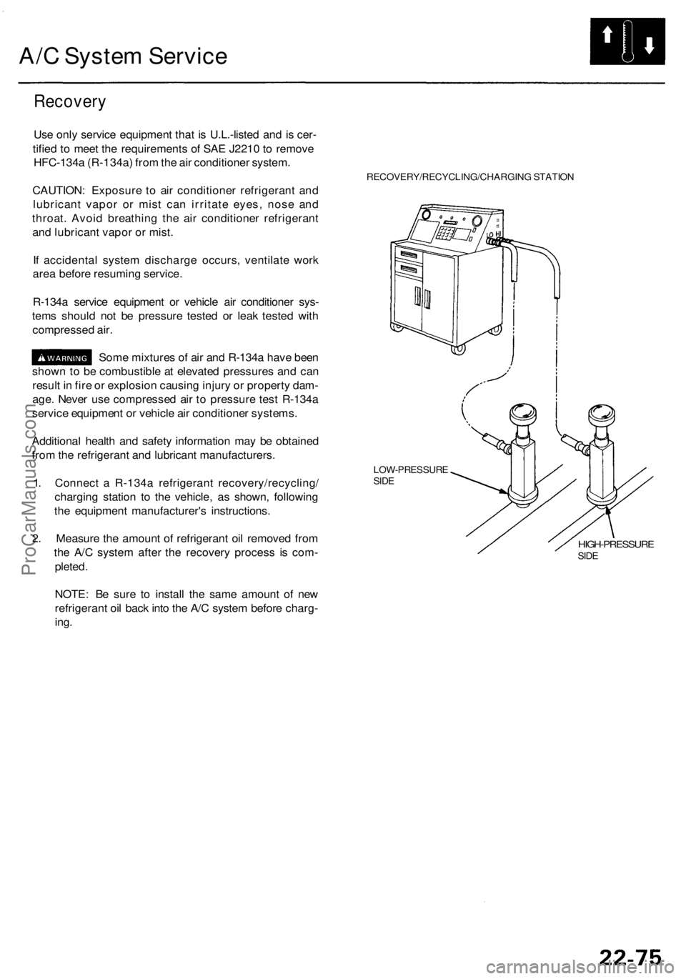
A/C System Service
Recovery
Use only service equipment that is U.L.-listed and is cer-
tified to meet the requirements of SAE J2210 to remove
HFC-134a (R-134a) from the air conditioner system.
CAUTION: Exposure to air conditioner refrigerant and
lubricant vapor or mist can irritate eyes, nose and
throat. Avoid breathing the air conditioner refrigerant
and lubricant vapor or mist.
If accidental system discharge occurs, ventilate work
area before resuming service.
R-134a service equipment or vehicle air conditioner sys-
tems should not be pressure tested or leak tested with
compressed air.
Some mixtures of air and R-134a have been
shown to be combustible at elevated pressures and can
result in fire or explosion causing injury or property dam-
age. Never use compressed air to pressure test R-134a
service equipment or vehicle air conditioner systems.
Additional health and safety information may be obtained
from the refrigerant and lubricant manufacturers.
1. Connect a R-134a refrigerant recovery/recycling/
charging station to the vehicle, as shown, following
the equipment manufacturer's instructions.
2. Measure the amount of refrigerant oil removed from
the A/C system after the recovery process is com-
pleted.
RECOVERY/RECYCLING/CHARGING STATION
LOW-PRESSURE
SIDE
HIGH-PRESSURE
SIDE
NOTE: Be sure to install the same amount of new
refrigerant oil back into the A/C system before charg-
ing.ProCarManuals.com
Page 1493 of 1954
A/C Syste m Servic e
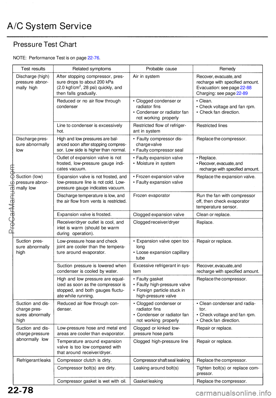
Pressur e Tes t Char t
NOTE : Performanc e Tes t i s o n pag e 22-76 .
Test result s
Discharg e (high )
pressur e abnor -
mall y hig h
Discharg e pres -
sur e abnormall y
low
Suctio n (low )
pressur e abnor -
mally lo w
Suctio n pres -
sur e abnormall y
high
Suctio n an d dis -
charg e pres -
sure s abnormall y
hig h
Suctio n an d dis -
charg e pressur e
abnormall y lo w
Refrigeran t leak s
Relate d symptom s
After stoppin g compressor , pres -
sur e drop s t o abou t 20 0 kP a
(2. 0 kgf/cm
2, 2 8 psi ) quickly , an d
the n fall s gradually .
Reduce d o r n o ai r flo w throug h
condense r
Lin e to condense r i s excessivel y
hot.
Hig h an d lo w pressure s ar e bal -
ance d soo n afte r stoppin g compres -
sor . Lo w sid e is highe r tha n normal .
Outle t o f expansio n valv e is no t
frosted , low-pressur e gaug e indi -
cate s vacuum .
Expansio n valv e is no t frosted , an d
low-pressur e lin e is no t cold . Low -
pressur e gaug e indicate s vacuum .
Discharg e temperatur e is low , an d
th e ai r flo w fro m vent s i s restricted .
Expansio n valv e is frosted .
Receiver/drye r outle t i s cool , an d
inle t i s war m (shoul d b e war m
durin g operation) .
Low-pressur e hos e an d chec k
join t ar e coole r tha n th e tempera -
tur e aroun d evaporator .
Suctio n pressur e is lowere d whe n
condense r i s coole d b y water .
Hig h an d lo w pressur e ar e equal -
ize d a s soo n a s th e compresso r i s
stopped , an d bot h gauge s fluctu -
ate whil e running .
Reduce d ai r flo w throug h con -
denser .
Low-pressur e hos e an d meta l en d
area s ar e coole r tha n evaporator .
Temperatur e aroun d expansio n
valv e i s to o lo w compare d wit h
tha t aroun d receiver/dryer .
Compresso r clutc h i s dirty .
Compresso r bolt(s ) ar e dirty .
Compresso r gaske t i s we t wit h oil . Probabl
e caus e
Ai r i n syste m
• Clogge d condense r o r
radiato r fin s
• Condense r o r radiato r fa n
no t workin g properl y
Restricte d flo w o f refriger -
an t i n syste m
• Fault y compresso r dis -
charg e valv e
• Fault y compresso r sea l
• Fault y expansio n valv e
• Moistur e in syste m
• Froze n expansio n valv e
• Fault y expansio n valv e
Froze n evaporato r
Clogged expansio n valv e
Clogge d receiver/drye r
• Expansio n valv e ope n to o
lon g
• Loos e expansio n capillar y
tub e
Excessiv e refrigeran t i n sys -
tem
• Fault y gaske t
• Fault y high-pressur e valv e
• Foreig n particl e stuc k in
high-pressur e valv e
• Clogge d condense r o r
radiato r fin s
• Condense r o r radiato r fa n
no t workin g properl y
Clogge d o r kinke d low -
pressur e hos e part s
Clogge d high-pressur e lin e
Compresso r shaf t sea l leakin g
Leakin g aroun d bolt(s )
Gaske t leakin g Remed
y
Recover , evacuate , an d
recharg e wit h specifie d amount .
Evacuation : se e pag e 22-8 8
Charging : se e pag e 22-8 9
• Clean .
• Chec k voltag e an d fa n rpm .
• Chec k fa n direction .
Restricte d line s
Replac e th e compressor .
• Replace .
• Recover , evacuate , an d
recharg e wit h specifie d amount .
Replac e th e expansio n valve .
Ru n th e fa n wit h compresso r
off , the n chec k evaporato r
temperatur e sensor .
Clea n o r replace .
Replace .
Repair o r replace .
Recover , evacuate , an d
recharg e wit h specifie d amount .
Replac e th e compressor .
• Clea n condense r an d radia -
tor.
• Chec k voltag e an d fa n rpm .
• Chec k fa n direction .
Repai r o r replace .
Repai r o r replace .
Replac e th e compressor .
Tighte n bolt(s ) o r replac e com -
pressor .
Replace th e compressor .
ProCarManuals.com