transmission ACURA RL KA9 1996 Service Manual PDF
[x] Cancel search | Manufacturer: ACURA, Model Year: 1996, Model line: RL KA9, Model: ACURA RL KA9 1996Pages: 1954, PDF Size: 61.44 MB
Page 893 of 1954
Transmission
Reassembly (cont'd )
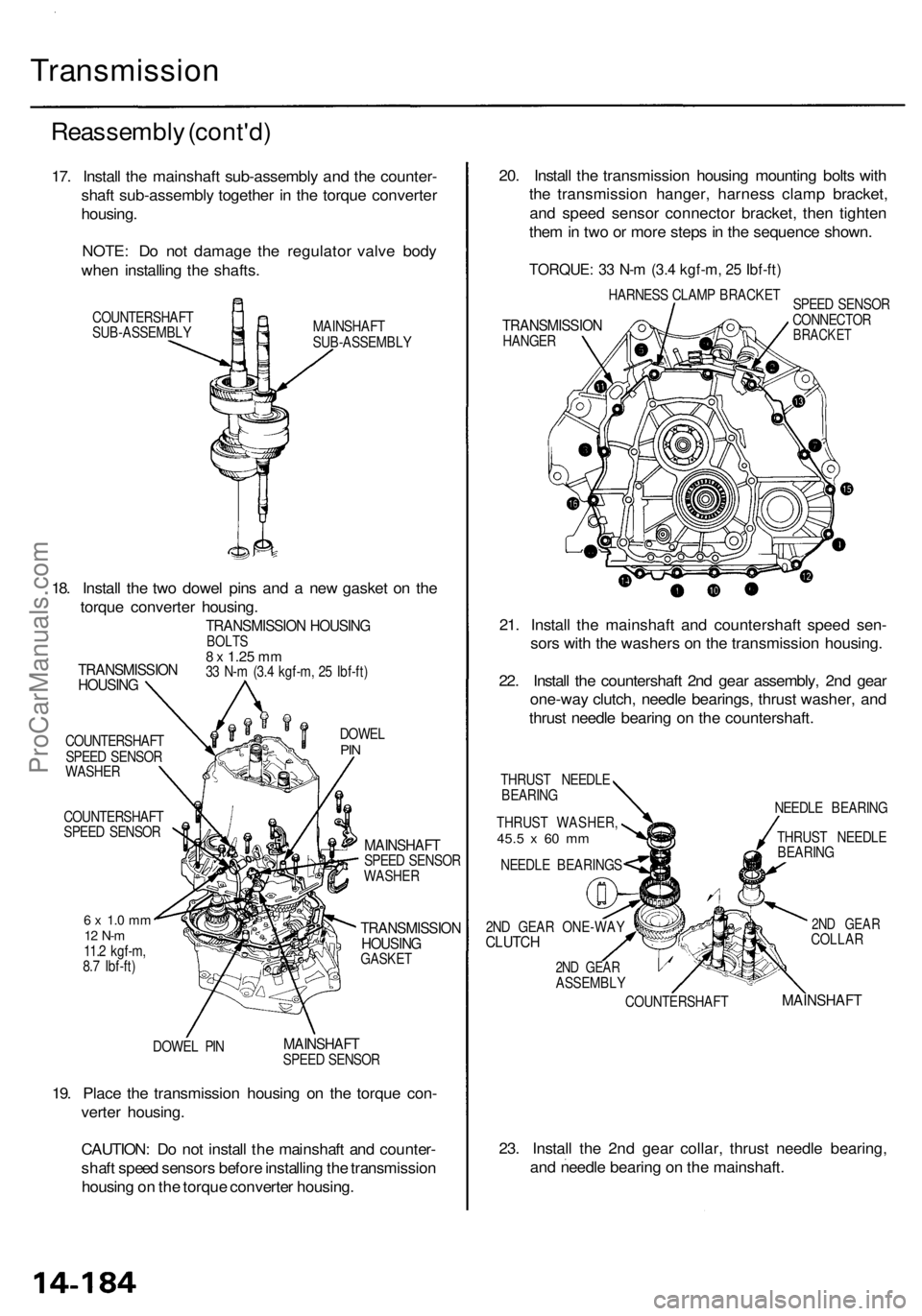
17. Instal l th e mainshaf t sub-assembl y an d th e counter -
shaf t sub-assembl y togethe r i n th e torqu e converte r
housing .
NOTE : D o no t damag e th e regulato r valv e bod y
whe n installin g th e shafts .
COUNTERSHAF T
SUB-ASSEMBL Y MAINSHAF
T
SUB-ASSEMBL Y
COUNTERSHAF T
SPEE D SENSO R
WASHE R
COUNTERSHAF T
SPEE D SENSO R
6 x 1. 0 m m12 N- m11.2 kgf-m ,
8. 7 Ibf-ft )
DOWE L PI N DOWE
L
PIN
MAINSHAF TSPEED SENSO R
WASHE R
TRANSMISSIO NHOUSINGGASKET
MAINSHAF TSPEED SENSO R
19. Plac e th e transmissio n housin g o n th e torqu e con -
verte r housing .
CAUTION : D o no t instal l th e mainshaf t an d counter -
shaf t spee d sensor s befor e installin g th e transmissio n
housin g o n th e torqu e converte r housing . 20
. Instal l th e transmissio n housin g mountin g bolt s wit h
th e transmissio n hanger , harnes s clam p bracket ,
an d spee d senso r connecto r bracket , the n tighte n
the m in tw o o r mor e step s in th e sequenc e shown .
TORQUE : 3 3 N- m (3. 4 kgf-m , 2 5 Ibf-ft )
HARNES S CLAM P BRACKE T
TRANSMISSIO NHANGER SPEE
D SENSO R
CONNECTO RBRACKET
21. Instal l th e mainshaf t an d countershaf t spee d sen -
sor s wit h th e washer s o n th e transmissio n housing .
22 . Instal l th e countershaf t 2n d gea r assembly , 2n d gea r
one-wa y clutch , needl e bearings , thrus t washer , an d
thrus t needl e bearin g o n th e countershaft .
THRUST NEEDL E
BEARIN G
THRUS T WASHER ,
45.5 x 60 m m
NEEDL E BEARING S NEEDL
E BEARIN G
COUNTERSHAF TTHRUS
T NEEDL E
BEARIN G
2ND GEA RCOLLA R
MAINSHAF T
23. Instal l th e 2n d gea r collar , thrus t needl e bearing ,
an d needl e bearin g o n th e mainshaft .
TRANSMISSIO NHOUSING
TRANSMISSIO N HOUSIN GBOLTS8 x 1.2 5 mm33 N- m (3. 4 kgf-m , 2 5 Ibf-ft )
18. Instal l th e tw o dowe l pin s an d a ne w gaske t o n th e
torqu e converte r housing .
2ND GEA R ONE-WA YCLUTCH
2ND GEA RASSEMBL Y
ProCarManuals.com
Page 895 of 1954
Transmission
Reassembly (cont'd )
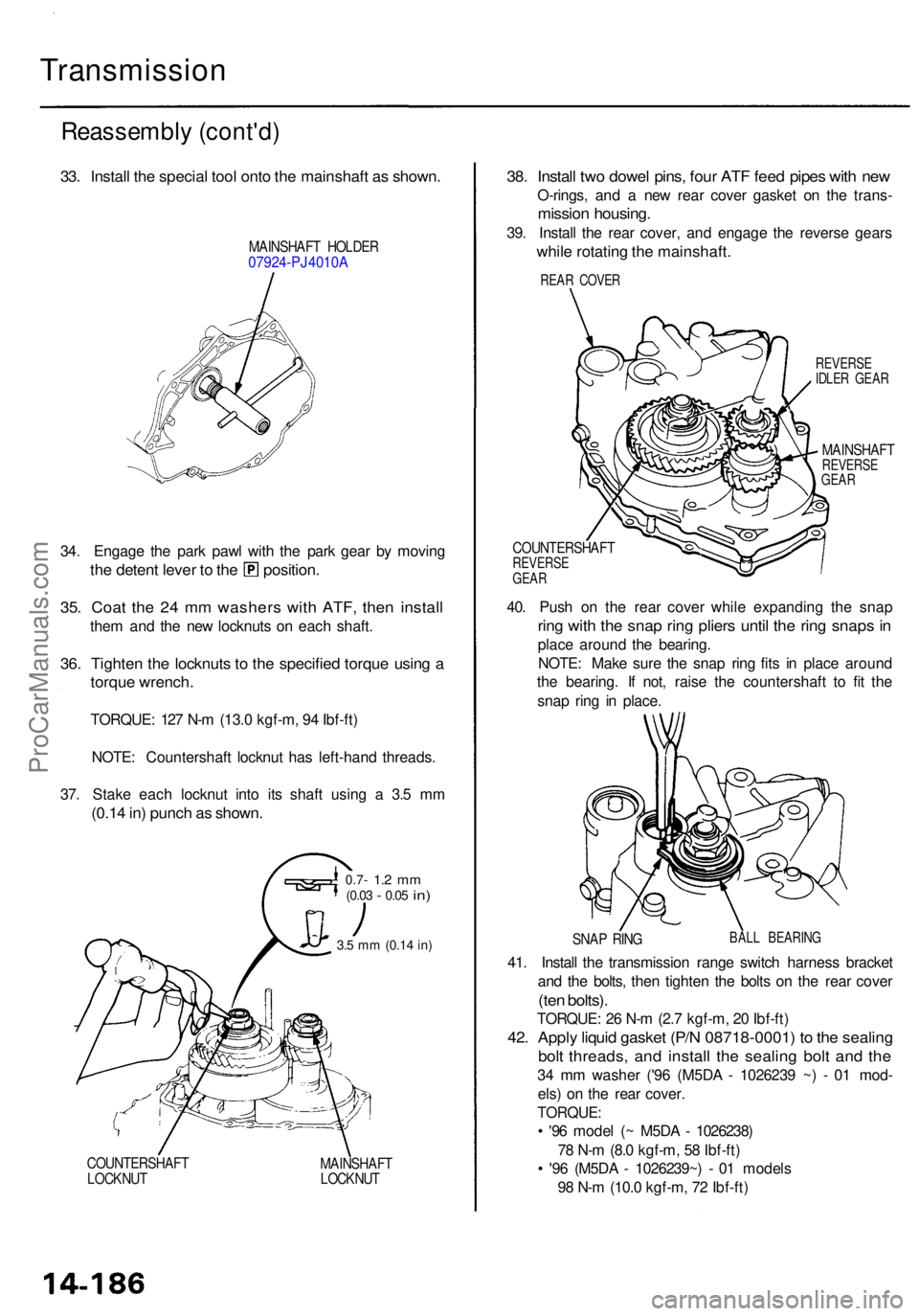
33. Instal l th e specia l too l ont o th e mainshaf t a s shown .
MAINSHAF T HOLDE R07924-PJ4010 A
34. Engag e th e par k paw l wit h th e par k gea r b y movin g
the deten t leve r t o th e position .
35. Coa t th e 2 4 m m washer s wit h ATF , the n instal l
them an d th e ne w locknut s o n eac h shaft .
36. Tighte n th e locknut s t o th e specifie d torqu e usin g a
torqu e wrench .
TORQUE : 12 7 N- m (13. 0 kgf-m , 9 4 Ibf-ft )
NOTE : Countershaf t locknu t ha s left-han d threads .
37 . Stak e eac h locknu t int o it s shaf t usin g a 3. 5 m m
(0.1 4 in ) punc h a s shown .
0.7- 1.2 m m(0.0 3 - 0.05 in)
3.5 m m (0.1 4 in )
COUNTERSHAF T
LOCKNU T MAINSHAF
T
LOCKNU T
38. Instal l tw o dowe l pins , fou r AT F fee d pipe s wit h ne w
O-rings , an d a ne w rea r cove r gaske t o n th e trans -
mission housing .
39. Instal l th e rea r cover , an d engag e th e revers e gear s
while rotatin g th e mainshaft .
REVERSE
IDLE R GEA R
MAINSHAF TREVERSE
GEA R
COUNTERSHAF TREVERSEGEAR
40. Pus h o n th e rea r cove r whil e expandin g th e sna p
ring wit h th e sna p rin g plier s unti l th e rin g snap s i n
plac e aroun d th e bearing .
NOTE : Mak e sur e th e sna p rin g fit s i n plac e aroun d
th e bearing . I f not , rais e th e countershaf t t o fi t th e
sna p rin g i n place .
SNAP RIN GBAL L BEARIN G
41. Instal l th e transmissio n rang e switc h harnes s bracke t
an d th e bolts , the n tighte n th e bolt s o n th e rea r cove r
(ten bolts) .
TORQUE : 2 6 N- m (2. 7 kgf-m , 2 0 Ibf-ft )
42. Appl y liqui d gaske t (P/ N 08718-0001 ) t o th e sealin g
bolt threads , an d instal l th e sealin g bol t an d th e
34 m m washe r ('9 6 (M5D A - 102623 9 ~ ) - 0 1 mod -
els ) o n th e rea r cover .
TORQUE :
• '9 6 mode l ( ~ M5D A - 1026238 )
7 8 N- m (8. 0 kgf-m , 5 8 Ibf-ft )
• '9 6 (M5D A - 1026239~ ) - 0 1 model s
9 8 N- m (10. 0 kgf-m , 7 2 Ibf-ft )
REAR COVE R
ProCarManuals.com
Page 898 of 1954
Transmission
Installation
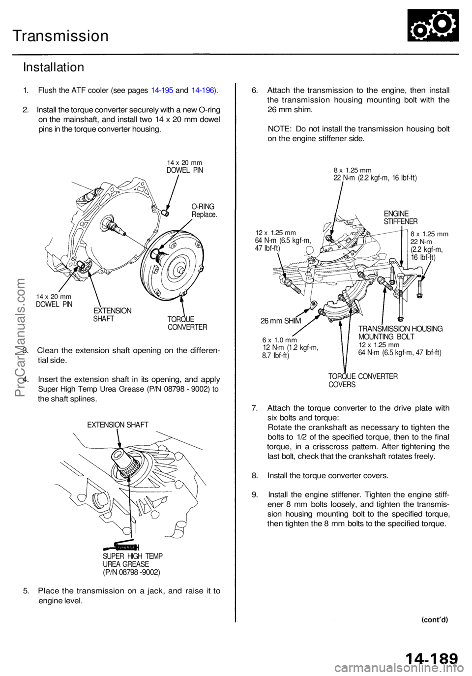
1. Flus h th e AT F coole r (se e page s 14-19 5 an d 14-196 ).
2 . Instal l th e torqu e converte r securel y wit h a ne w O-rin g
o n th e mainshaft , an d instal l tw o 1 4 x 2 0 m m dowe l
pin s in th e torqu e converte r housing .
14 x 20 m mDOWE L PI N
O-RIN G
Replace .
14 x 20 m mDOWE L PI NEXTENSIO NSHAFT
TORQUE
CONVERTE R
3. Clea n th e extensio n shaf t openin g o n th e differen -
tia l side .
4 . Inser t th e extensio n shaf t i n it s opening , an d appl y
Supe r Hig h Tem p Ure a Greas e (P/ N 0879 8 - 9002 ) t o
th e shaf t splines .
EXTENSIO N SHAF T
5. Plac e th e transmissio n o n a jack , an d rais e i t t o
engin e level . 6
. Attac h th e transmissio n t o th e engine , the n instal l
th e transmissio n housin g mountin g bol t wit h th e
2 6 m m shim .
NOTE : D o no t instal l th e transmissio n housin g bol t
o n th e engin e stiffene r side .
8 x 1.2 5 mm22 N- m (2. 2 kgf-m , 1 6 Ibf-ft )
ENGIN ESTIFFENE R
12 x 1.2 5 mm64 N- m (6. 5 kgf-m ,
4 7 Ibf-ft )8 x 1.2 5 mm22 N- m(2.2 kgf-m ,
1 6 Ibf-ft )
26 m m SHI M
6 x 1. 0 m m12 N- m (1. 2 kgf-m ,
8. 7 Ibf-ft )
TRANSMISSIO N HOUSIN GMOUNTIN G BOL T12 x 1.2 5 mm64 N- m (6. 5 kgf-m , 4 7 Ibf-ft )
TORQU E CONVERTE R
COVER S
7. Attac h th e torqu e converte r t o th e driv e plat e wit h
si x bolt s an d torque :
Rotat e th e crankshaf t a s necessar y t o tighte n th e
bolt s t o 1/ 2 o f th e specifie d torque , the n t o th e fina l
torque , i n a crisscros s pattern . Afte r tightenin g th e
las t bolt , chec k tha t th e crankshaf t rotate s freely .
8 . Instal l th e torqu e converte r covers .
9 . Instal l th e engin e stiffener . Tighte n th e engin e stiff -
ene r 8 m m bolt s loosely , an d tighte n th e transmis -
sio n housin g mountin g bol t t o th e specifie d torque ,
the n tighte n th e 8 m m bolt s t o th e specifie d torque .
SUPER HIG H TEM P
URE A GREAS E
(P/N 0879 8 -9002 )
ProCarManuals.com
Page 899 of 1954
Transmission
Installation (cont'd )
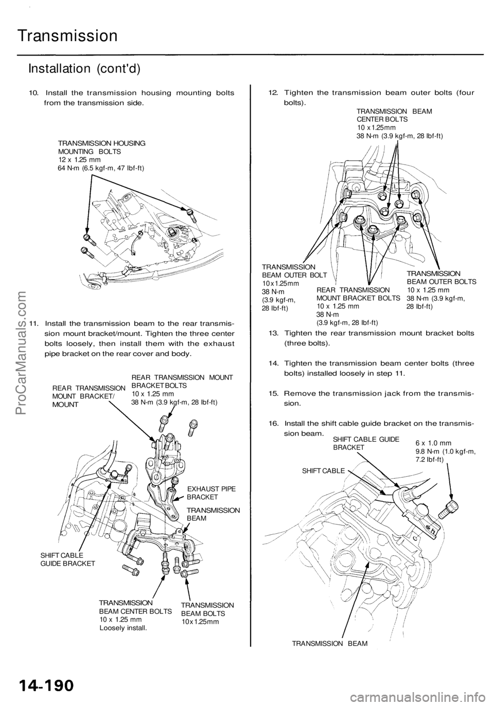
10. Instal l th e transmissio n housin g mountin g bolt s
fro m th e transmissio n side .
TRANSMISSIO N HOUSIN GMOUNTIN G BOLT S12 x 1.2 5 mm64 N- m (6. 5 kgf-m , 4 7 Ibf-ft )
11. Instal l th e transmissio n bea m to th e rea r transmis -
sio n moun t bracket/mount . Tighte n th e thre e cente r
bolt s loosely , the n instal l the m with the exhaus t
pip e bracke t o n th e rea r cove r an d body .
EXHAUS T PIP EBRACKE T
TRANSMISSIO NBEAM
SHIF T CABL E
GUID E BRACKE T
TRANSMISSIO NBEAM CENTE R BOLT S10 x 1.2 5 mmLoosel y install .
12. Tighte n th e transmissio n bea m oute r bolt s (fou r
bolts) .
13 . Tighte n th e rea r transmissio n moun t bracke t bolt s
(thre e bolts) .
14 . Tighte n th e transmissio n bea m cente r bolt s (thre e
bolts ) installe d loosel y in ste p 11 .
15 . Remov e th e transmissio n jac k fro m th e transmis -
sion .
16 . Instal l th e shif t cabl e guid e bracke t o n th e transmis -
sio n beam .
SHIFT CABL E GUID EBRACKE T
TRANSMISSIO N BEA M
6 x 1. 0 m m9.8 N- m (1. 0 kgf-m ,
7. 2 Ibf-ft )
SHIF T CABL E
TRANSMISSIO NBEAM BOLT S10 x 1.2 5 m m
REA R TRANSMISSIO N
MOUN T BRACKET /
MOUNT
REAR TRANSMISSIO N MOUN T
BRACKE T BOLT S
10 x 1.2 5 mm38 N- m (3. 9 kgf-m , 2 8 Ibf-ft ) TRANSMISSIO
N BEA M
CENTE R BOLT S
10 x 1.2 5 m m38 N- m (3. 9 kgf-m , 2 8 Ibf-ft )
TRANSMISSIO NBEAM OUTE R BOL T10 x 1.2 5 m m38 N- m(3.9 kgf-m ,
2 8 Ibf-ft )
TRANSMISSIO NBEAM OUTE R BOLT S10 x 1.2 5 mm38 N- m (3. 9 kgf-m ,
2 8 Ibf-ft )
REA
R TRANSMISSIO N
MOUN T BRACKE T BOLT S10 x 1.2 5 mm38 N- m(3.9 kgf-m , 2 8 Ibf-ft )
ProCarManuals.com
Page 901 of 1954
Transmission
Installation (cont'd )
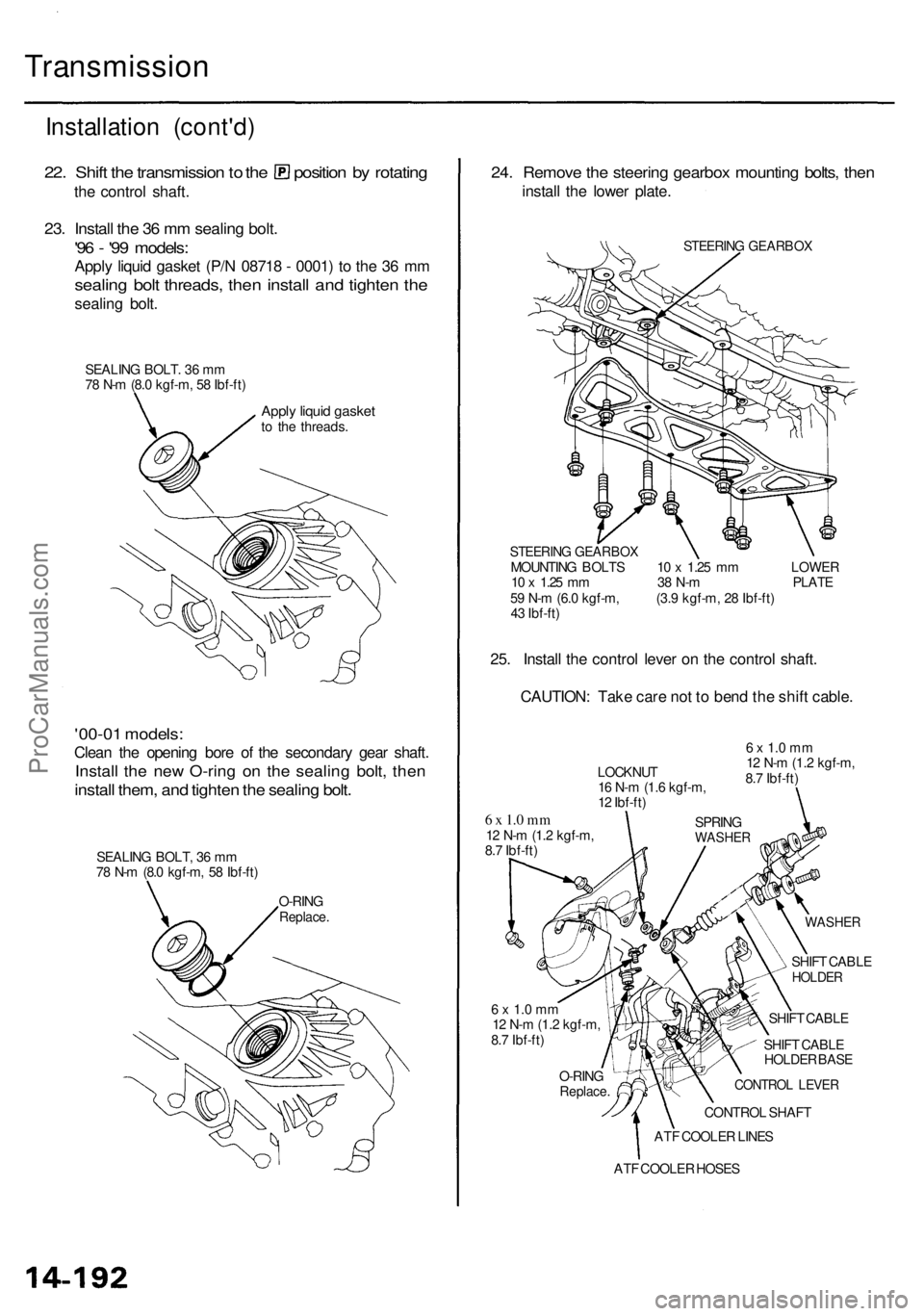
22. Shif t th e transmissio n to th e positio n b y rotatin g
the contro l shaft .
23. Instal l th e 3 6 m m sealin g bolt .
'96 - '9 9 models :
Apply liqui d gaske t (P/ N 0871 8 - 0001 ) t o th e 3 6 m m
sealin g bol t threads , the n instal l an d tighte n th e
sealin g bolt .
SEALIN G BOLT . 3 6 m m
7 8 N- m (8. 0 kgf-m , 5 8 Ibf-ft )
Apply liqui d gaske tto th e threads .
'00-01 models :
Clean th e openin g bor e o f th e secondar y gea r shaft .
Install th e ne w O-rin g o n th e sealin g bolt , the n
instal l them , an d tighte n th e sealin g bolt .
SEALIN G BOLT , 3 6 m m
7 8 N- m (8. 0 kgf-m , 5 8 Ibf-ft )
O-RIN G
Replace .
24. Remov e th e steerin g gearbo x mountin g bolts , the n
instal l th e lowe r plate .
STEERIN G GEARBO X
STEERIN G GEARBO X
MOUNTING BOLT S 1 0 x 1.2 5 m m LOWE R
1 0 x 1.2 5 m m 3 8 N- m PLAT E
5 9 N- m (6. 0 kgf-m , (3. 9 kgf-m , 2 8 Ibf-ft )
4 3 Ibf-ft )
25. Instal l th e contro l leve r o n th e contro l shaft .
CAUTION : Tak e car e no t t o ben d th e shif t cable .
6 x 1. 0 m m12 N- m (1. 2 kgf-m ,
8. 7 Ibf-ft )
WASHE R
LOCKNU T
1 6 N- m (1. 6 kgf-m ,
1 2 Ibf-ft )
SPRING
WASHE R
6 x 1. 0 m m12 N- m (1. 2 kgf-m ,
8. 7 Ibf-ft )
SHIFT CABL E
HOLDE R
SHIFT CABL E
SHIF T CABL E
HOLDE R BAS E
CONTRO L LEVE R
CONTRO L SHAF T
AT F COOLE R LINE S
O-RIN
G
Replace .
6 x 1. 0 m m12 N- m (1. 2 kgf-m ,
8. 7 Ibf-ft )
ATF COOLE R HOSE S
ProCarManuals.com
Page 903 of 1954
Transmission
Installation (cont'd )
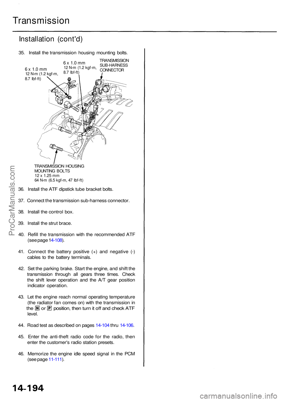
TRANSMISSIO N HOUSIN GMOUNTIN G BOLT S12 x 1.2 5 m m64 N- m (6. 5 kgf-m , 4 7 Ibf-ft )
36. Instal l th e AT F dipstic k tub e bracke t bolts .
37 . Connec t th e transmissio n sub-harnes s connector .
38 . Instal l th e contro l box .
39 . Instal l th e stru t brace .
40 . Refil l th e transmissio n wit h th e recommende d AT F
(se e pag e 1 4-108 ).
41 . Connec t th e batter y positiv e (+ ) an d negativ e (- )
cable s t o th e batter y terminals .
42 . Se t th e parkin g brake . Star t th e engine , an d shif t th e
transmissio n throug h al l gear s thre e times . Chec k
th e shif t leve r operatio n an d th e A/ T gea r positio n
indicato r operation .
43 . Le t th e engin e reac h norma l operatin g temperatur e
(th e radiato r fa n come s on ) wit h th e transmissio n in
th e o r position , the n tur n it of f an d chec k AT F
level .
44 . Roa d tes t a s describe d o n page s 14-10 4 thr u 14-106 .
45 . Ente r th e anti-thef t radi o cod e fo r th e radio , the n
ente r th e customer' s radi o statio n presets .
46 . Memoriz e th e engin e idl e spee d signa l i n th e PC M
(se e pag e 11-111 ).
35
. Instal l th e transmissio n housin g mountin g bolts .
TRANSMISSIO NSUB-HARNES SCONNECTOR
6 x 1. 0 m m12 N- m (1. 2 kgf-m ,8.7 Ibf-ft )6 x 1. 0 m m12 N- m (1. 2 kgf-m ,8.7 Ibf-ft )
ProCarManuals.com
Page 904 of 1954
Cooler Flushing
To prevent injury to face and eyes, always
wear safety glasses or a face shield when using the
transmission flusher.
NOTE: This procedure should be performed before rein-
stalling the transmission.
1. Check tool and hoses for wear or cracks before using.
Replace parts that are worn or cracked.
2. Using the measuring cup, fill the tank with 21 ounces
(approximately 2/3 full) of biodegradable flushing
fluid (J35944 - 20). Do not substitute with any other
fluid. Follow the handling procedure on the fluid
container.
3. Secure the flusher filler cap, and pressurize the tank
with compressed air to between 550 - 829 kpa (5.6 -
8.45 kgf/cm2, 80-120psi).
NOTE: The air line should be equipped with a water
trap to ensure a dry air system.
4. Hang the tool under the vehicle.
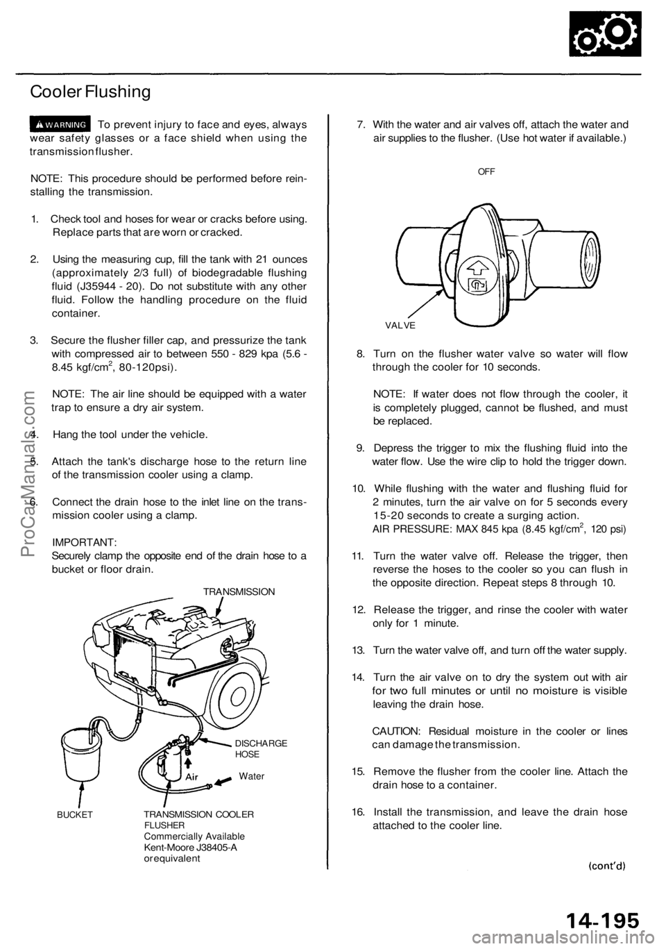
5. Attach the tank's discharge hose to the return line
of the transmission cooler using a clamp.
6. Connect the drain hose to the inlet line on the trans-
mission cooler using a clamp.
IMPORTANT:
Securely clamp the opposite end of the drain hose to a
bucket or floor drain.
TRANSMISSION
DISCHARGE
HOSE
BUCKET
TRANSMISSION COOLER
FLUSHER
Commercially Available
Kent-Moore J38405-A
or equivalent
7. With the water and air valves off, attach the water and
air supplies to the flusher. (Use hot water if available.)
OFF
VALVE
8. Turn on the flusher water valve so water will flow
through the cooler for 10 seconds.
NOTE: If water does not flow through the cooler, it
is completely plugged, cannot be flushed, and must
be replaced.
9. Depress the trigger to mix the flushing fluid into the
water flow. Use the wire clip to hold the trigger down.
10. While flushing with the water and flushing fluid for
2 minutes, turn the air valve on for 5 seconds every
15-20 seconds to create a surging action.
AIR PRESSURE: MAX 845 kpa (8.45 kgf/cm2, 120 psi)
11. Turn the water valve off. Release the trigger, then
reverse the hoses to the cooler so you can flush in
the opposite direction. Repeat steps 8 through 10.
12. Release the trigger, and rinse the cooler with water
only for 1 minute.
13. Turn the water valve off, and turn off the water supply.
14. Turn the air valve on to dry the system out with air
for two full minutes or until no moisture is visible
leaving the drain hose.
CAUTION: Residual moisture in the cooler or lines
can damage the transmission.
15. Remove the flusher from the cooler line. Attach the
drain hose to a container.
16. Install the transmission, and leave the drain hose
attached to the cooler line.
WaterProCarManuals.com
Page 905 of 1954
Transmission
Cooler Flushin g (cont'd )
17. Mak e sur e th e transmissio n is in th e position .
Then fil l th e transmissio n wit h ATF , an d ru n th e
engin e fo r 3 0 second s o r unti l approximatel y 0.9 5
(1. 0 U S qt. , 0. 8 Im p qt. ) i s discharged .
18 . Remov e th e drai n hose , an d reconnec t th e coole r
retur n hos e to th e transmissio n (se e nex t column) .
19 . Refil l th e transmissio n wit h th e recommende d AT F
t o th e prope r leve l (se e pag e 14-108 ).
TOO L MAINTENANC E
1 . Empt y an d rins e afte r eac h use . Fil l th e ca n wit h wate r
an d pressuriz e th e can . Flus h th e discharg e lin e t o
ensur e tha t th e uni t i s clean .
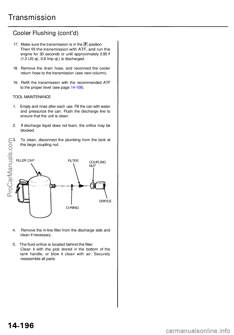
2 . I f discharg e liqui d doe s no t foam , th e orific e ma y b e
blocked .
3 . T o clean , disconnec t th e plumbin g fro m th e tan k a t
the larg e couplin g nut .
FILLE R CA PFILTE RCOUPLIN GNUT
O-RIN G
ORIFIC E
4. Remov e th e in-lin e filte r fro m th e discharg e sid e an d
clea n if necessary .
5. Th e flui d orific e is locate d behin d th e filter .
Clea n i t wit h th e pic k store d i n th e botto m o f th e
tan k handle , o r blo w it clea n wit h air . Securel y
reassembl e al l parts .
ProCarManuals.com
Page 906 of 1954
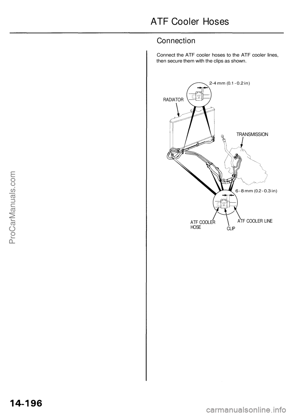
ATF Cooler Hoses
Connection
Connect the ATF cooler hoses to the ATF cooler lines,
then secure them with the clips as shown.
2-4 mm
(0.1
- 0.2 in)
RADIATOR
TRANSMISSION
6 - 8
mm
(0.2
-
0.3
in)
ATF COOLER
HOSE
CLIP
ATF COOLER LINEProCarManuals.com
Page 909 of 1954
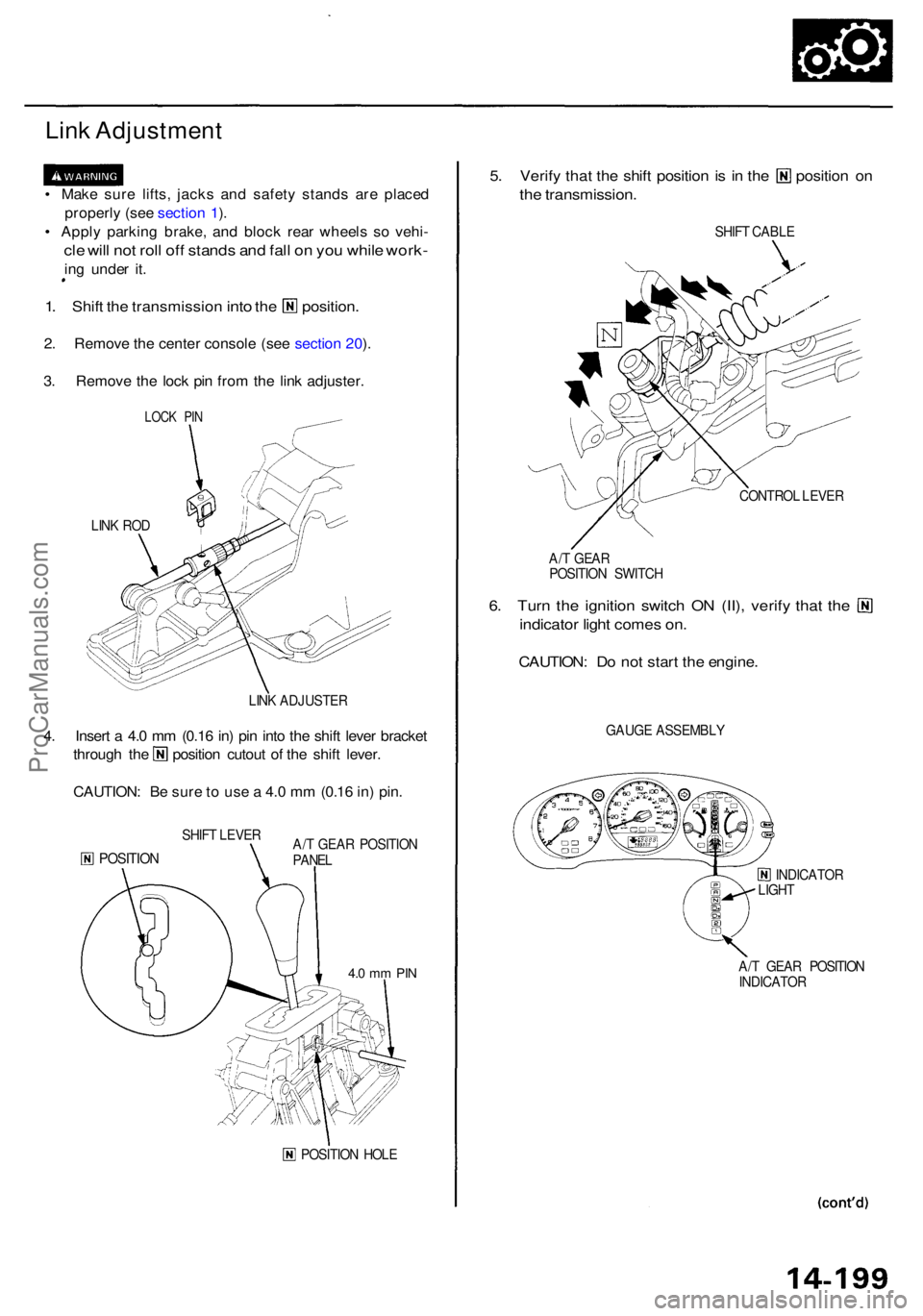
Link Adjustmen t
• Mak e sur e lifts , jack s an d safet y stand s ar e place d
properl y (se e sectio n 1 ).
• Appl y parkin g
brake, and bloc k rea r wheel s s o vehi -
cle wil l no t rol l of f stand s an d fal l o n yo u whil e work -
ing unde r it .
1. Shif t the transmissio n into the position .
2. Remov e th e cente r consol e (se e sectio n 20 ).
3 . Remov e th e loc k pi n fro m th e lin k adjuster .
LINK RO D
LINK ADJUSTE R
4. Inser t a 4. 0 m m (0.1 6 in ) pi n int o th e shif t leve r bracke t
through th e positio n cutou t o f th e shif t lever .
CAUTION : B e sur e t o us e a 4. 0 m m (0.1 6 in ) pin .
SHIF T LEVE R
POSITIO NA/T GEA R POSITIO N
PANE L
POSITIO N HOL E
5. Verif y tha t th e shif t positio n is i n th e positio n o n
the transmission .
SHIFT CABL E
CONTRO L LEVE R
A/ T GEA R
POSITIO N SWITC H
6. Tur n th e ignitio n switc h O N (II) , verif y tha t th e
indicato r ligh t come s on .
CAUTION : D o no t star t th e engine .
GAUGE ASSEMBL Y
INDICATOR
LIGH T
A/ T GEA R POSITIO N
INDICATO R
LOCK PI N
4.0 m m PI N
ProCarManuals.com