brakes ACURA RL KA9 1996 Service Repair Manual
[x] Cancel search | Manufacturer: ACURA, Model Year: 1996, Model line: RL KA9, Model: ACURA RL KA9 1996Pages: 1954, PDF Size: 61.44 MB
Page 1 of 1954
General Info
Specifications
Maintenance
*Engine Electrical
Engine
Cooling
Fuel and Emissions
*TransaxleSteering
Suspension
*Brakes (Including ABS,
TCS and VSA)
*Body
*Heating, Ventilation and Air Conditioning
*Body Electrical
*Restraints
1996±0 4 3.5RL Main Menu
As sections w/ * include SRS components,
special precautions are required when servicing.
ProCarManuals.com
Page 96 of 1954
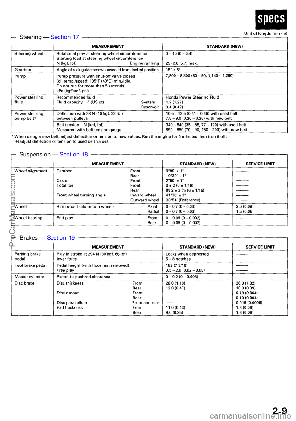
Brakes — Sectio n 1 9
Suspensio
n — Sectio n 1 8
Steerin g — Sectio n 1 7
ProCarManuals.com
Page 731 of 1954
Description
Electronic Control System (cont'd)
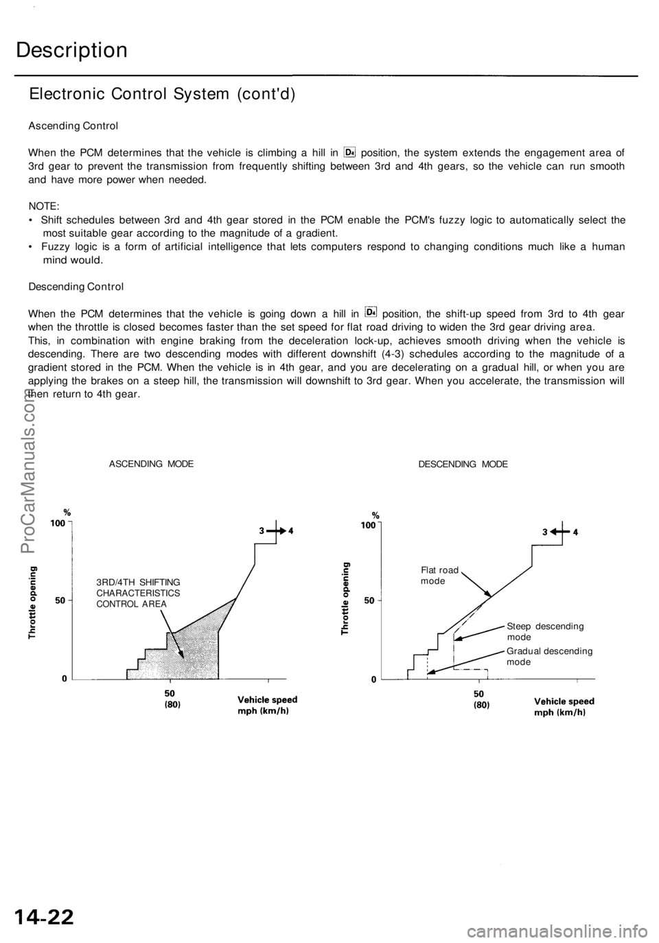
Ascending Control
When the PCM determines that the vehicle is climbing a hill in position, the system extends the engagement area of
3rd gear to prevent the transmission from frequently shifting between 3rd and 4th gears, so the vehicle can run smooth
and have more power when needed.
NOTE:
• Shift schedules between 3rd and 4th gear stored in the PCM enable the PCM's fuzzy logic to automatically select the
most suitable gear according to the magnitude of a gradient.
• Fuzzy logic is a form of artificial intelligence that lets computers respond to changing conditions much like a human
mind would.
Descending Control
When the PCM determines that the vehicle is going down a hill in position, the shift-up speed from 3rd to 4th gear
when the throttle is closed becomes faster than the set speed for flat road driving to widen the 3rd gear driving area.
This, in combination with engine braking from the deceleration lock-up, achieves smooth driving when the vehicle is
descending. There are two descending modes with different downshift (4-3) schedules according to the magnitude of a
gradient stored in the PCM. When the vehicle is in 4th gear, and you are decelerating on a gradual hill, or when you are
applying the brakes on a steep hill, the transmission will downshift to 3rd gear. When you accelerate, the transmission will
then return to 4th gear.
ASCENDING MODE
DESCENDING MODE
3RD/4TH SHIFTING
CHARACTERISTICS
CONTROL AREA
Flat road
mode
Steep descending
mode
Gradual descending
modeProCarManuals.com
Page 1050 of 1954
Inspection
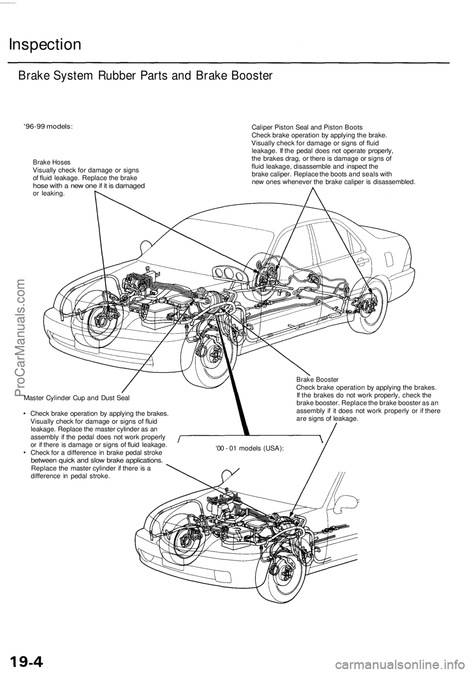
'96-99 models:
Brake Hoses
Visually check for damage or signs
of fluid leakage. Replace the brake
hose with a new one if it is damaged
or leaking.
Caliper Piston Seal and Piston Boots
Check brake operation by applying the brake.
Visually check for damage or signs of fluid
leakage. If the pedal does not operate properly,
the brakes drag, or there is damage or signs of
fluid leakage, disassemble and inspect the
brake caliper. Replace the boots and seals with
new ones whenever the brake caliper is disassembled.
Master Cylinder Cup and Dust Seal
Check brake operation by applying the brakes.
Visually check for damage or signs of fluid
leakage. Replace the master cylinder as an
assembly if the pedal does not work properly
or if there is damage or signs of fluid leakage.
Check for a difference in brake pedal stroke
between quick and slow brake applications.
Replace the master cylinder if there is a
difference in pedal stroke.
Brake Booster
Check brake operation by applying the brakes.
If the brakes do not work properly, check the
brake booster. Replace the brake booster as an
assembly if it does not work properly or if there
are signs of leakage.
Brake System Rubber Parts and Brake Booster
'00 - 01 models (USA):ProCarManuals.com
Page 1057 of 1954
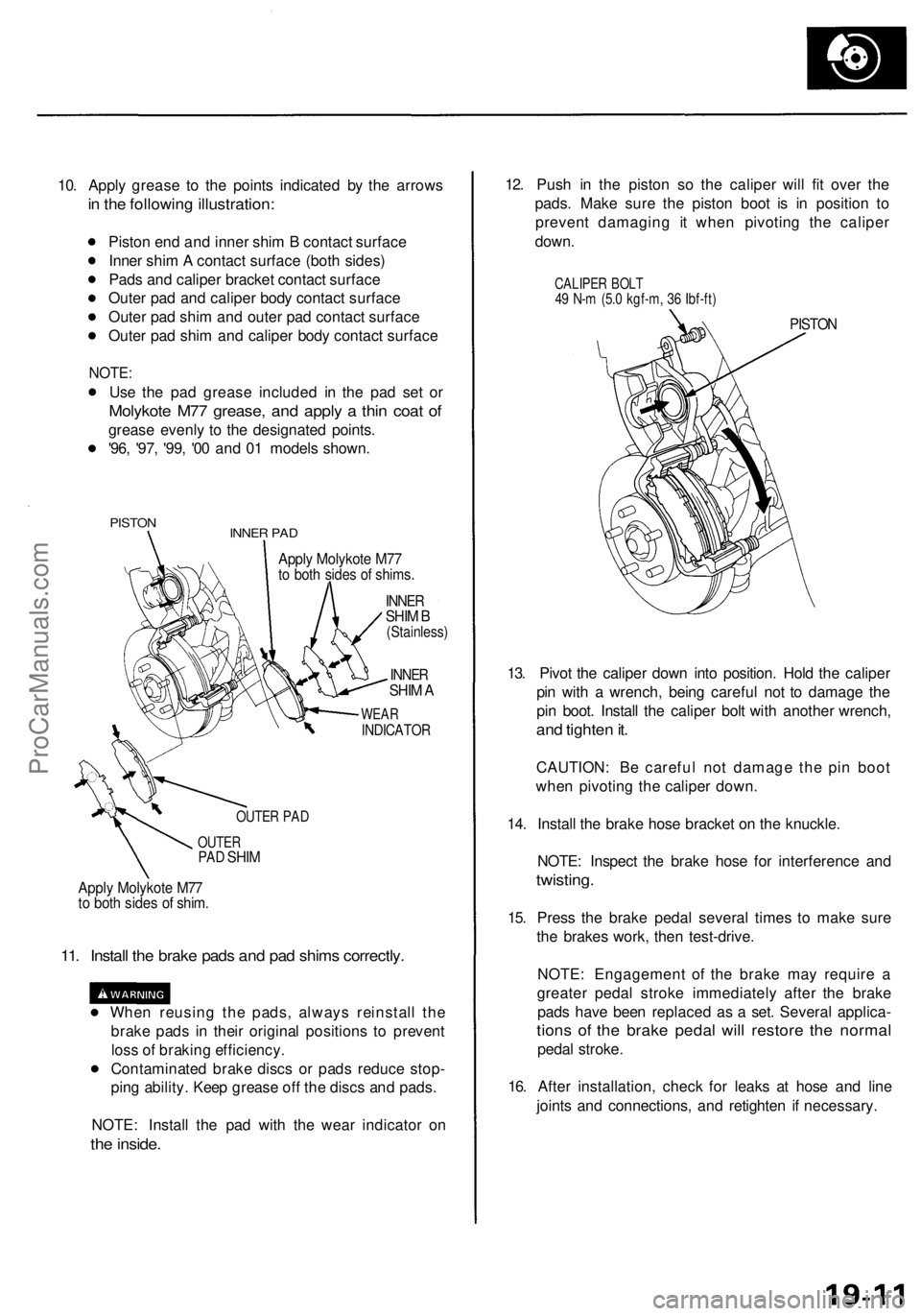
10. Apply grease to the points indicated by the arrows
in the following illustration:
Piston end and inner shim B contact surface
Inner shim A contact surface (both sides)
Pads and caliper bracket contact surface
Outer pad and caliper body contact surface
Outer pad shim and outer pad contact surface
Outer pad shim and caliper body contact surface
NOTE:
Use the pad grease included in the pad set or
Molykote M77 grease, and apply a thin coat of
grease evenly to the designated points.
'96, '97, '99, '00 and 01 models shown.
PISTON
INNER PAD
Apply Molykote M77
to both sides of shims.
INNER
SHIM B
(Stainless)
INNER
SHIM A
WEAR
INDICATOR
OUTER PAD
OUTER
PAD
SHIM
Apply Molykote M77
to both sides of shim.
11. Install the brake pads and pad shims correctly.
When reusing the pads, always reinstall the
brake pads in their original positions to prevent
loss of braking efficiency.
Contaminated brake discs or pads reduce stop-
ping ability. Keep grease off the discs and pads.
NOTE: Install the pad with the wear indicator on
the inside.
12. Push in the piston so the caliper will fit over the
pads. Make sure the piston boot is in position to
prevent damaging it when pivoting the caliper
down.
CALIPER BOLT
49 N-m (5.0 kgf-m, 36 Ibf-ft)
PISTON
13. Pivot the caliper down into position. Hold the caliper
pin with a wrench, being careful not to damage the
pin boot. Install the caliper bolt with another wrench,
and tighten it.
CAUTION: Be careful not damage the pin boot
when pivoting the caliper down.
14. Install the brake hose bracket on the knuckle.
NOTE: Inspect the brake hose for interference and
twisting.
15. Press the brake pedal several times to make sure
the brakes work, then test-drive.
NOTE: Engagement of the brake may require a
greater pedal stroke immediately after the brake
pads have been replaced as a set. Several applica-
tions of the brake pedal will restore the normal
pedal stroke.
16. After installation, check for leaks at hose and line
joints and connections, and retighten if necessary.ProCarManuals.com
Page 1066 of 1954
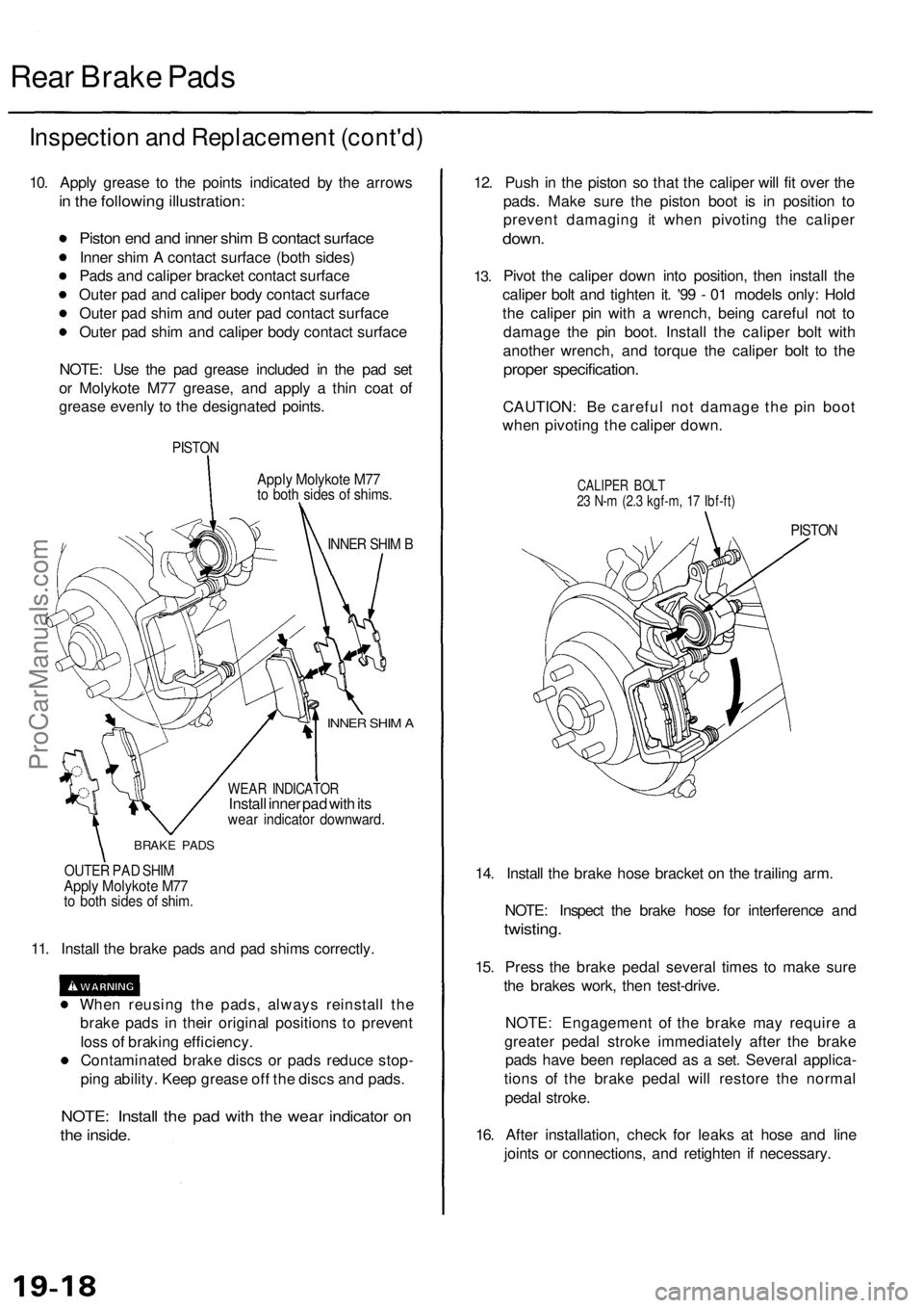
Rear Brake Pads
Inspection and Replacement (cont'd)
10. Apply grease to the points indicated by the arrows
in the following illustration:
Piston end and inner shim B contact surface
Inner shim A contact surface (both sides)
Pads and caliper bracket contact surface
Outer pad and caliper body contact surface
Outer pad shim and outer pad contact surface
Outer pad shim and caliper body contact surface
NOTE: Use the pad grease included in the pad set
or Molykote M77 grease, and apply a thin coat of
grease evenly to the designated points.
PISTON
Apply Molykote M77
to both sides of shims.
INNER SHIM B
INNER SHIM A
WEAR INDICATOR
Install inner pad with its
wear indicator downward.
BRAKE PADS
OUTER PAD SHIM
Apply Molykote M77
to both sides of shim.
11. Install the brake pads and pad shims correctly.
When reusing the pads, always reinstall the
brake pads in their original positions to prevent
loss of braking efficiency.
Contaminated brake discs or pads reduce stop-
ping ability. Keep grease off the discs and pads.
NOTE: Install the pad with the wear indicator on
the inside.
12. Push in the piston so that the caliper will fit over the
pads. Make sure the piston boot is in position to
prevent damaging it when pivoting the caliper
down.
13.
Pivot the caliper down into position, then install the
caliper bolt and tighten it. '99 - 01 models only: Hold
the caliper pin with a wrench, being careful not to
damage the pin boot. Install the caliper bolt with
another wrench, and torque the caliper bolt to the
proper specification.
CAUTION: Be careful not damage the pin boot
when pivoting the caliper down.
CALIPER BOLT
23 N-m (2.3 kgf-m, 17 Ibf-ft)
PISTON
14. Install the brake hose bracket on the trailing arm.
NOTE: Inspect the brake hose for interference and
twisting.
15. Press the brake pedal several times to make sure
the brakes work, then test-drive.
NOTE: Engagement of the brake may require a
greater pedal stroke immediately after the brake
pads have been replaced as a set. Several applica-
tions of the brake pedal will restore the normal
pedal stroke.
16. After installation, check for leaks at hose and line
joints or connections, and retighten if necessary.ProCarManuals.com
Page 1279 of 1954

Troubleshooting
DTC 71: Abnormal Wheel Speed Signal
Are any DTCs except 71 indicated?
Check the tires.
Are tires with specified size and
inflated to specification?
Check for brake drag.
Do the brakes drag?
Visually check for appropriate
wheel sensor and pulser installa-
tion (see table).
Are they installed correctly?
Check the four pulser gears for a
chipped tooth (see table).
Is the pulser OK?
Problem Verification:
1. Clear the DTC.
2. Test-drive the vehicle at 19
mph (30 km/h) or more.
3. Verify the DTC.
Is DTC 71 indicated?
YES
Check for loose terminals in the
VSA control unit 42P connector.
If necessary, substitute a known-
good VSA modulator-control
unit, and recheck.
Preform the appropriate trou-
bleshooting for the DTC.
Replace the tire(s) with the spec-
ified size.
Repair the brake drag.
Reinstall or replace the wheel
sensor or pulser.
Replace the driveshaft or hub
unit. (Chipped pulser gear.)
The system is OK at this time.
Verify the DTC.ProCarManuals.com