fog light ACURA RL KA9 1996 Service Repair Manual
[x] Cancel search | Manufacturer: ACURA, Model Year: 1996, Model line: RL KA9, Model: ACURA RL KA9 1996Pages: 1954, PDF Size: 61.44 MB
Page 166 of 1954
Idle Contro l Syste m
Idle Contro l Syste m
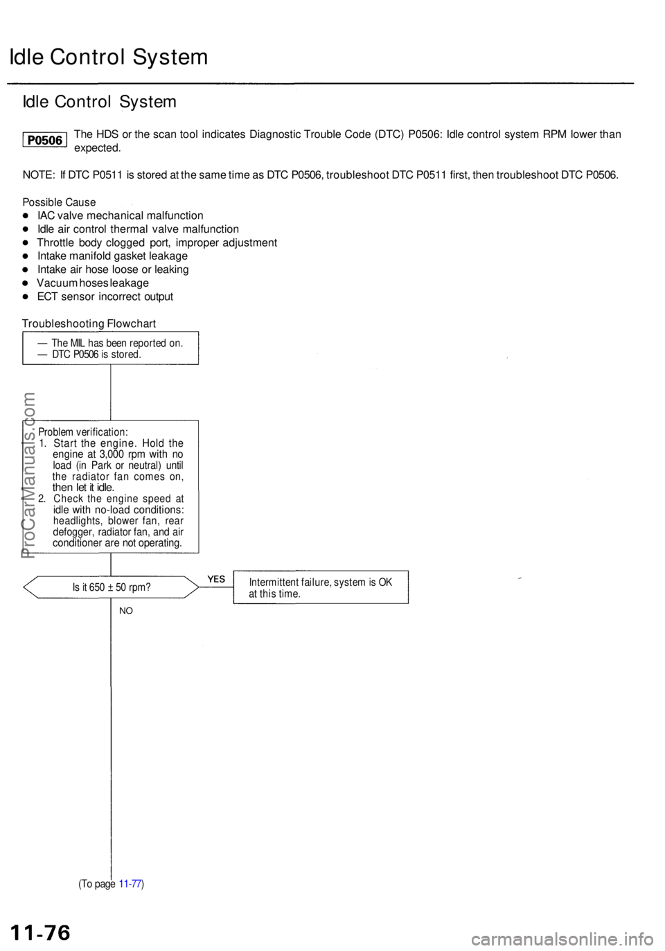
The HD S o r th e sca n too l indicate s Diagnosti c Troubl e Cod e (DTC ) P0506 : Idl e contro l syste m RP M lowe r tha n
expected .
NOTE : I f DT C P051 1 is store d a t th e sam e tim e a s DT C P0506 , troubleshoo t DT C P051 1 first , the n troubleshoo t DT C P0506 .
Possibl e Caus e
IAC valv e mechanica l malfunctio n
Idl e ai r contro l therma l valv e malfunction
Throttl e bod y clogge d port , imprope r adjustmen t
Intak e manifol d gaske t leakag e
Intak e ai r hos e loos e o r leakin g
Vacuu m hose s leakag e
EC T senso r incorrec t outpu t
Troubleshootin g Flowchar t
— Th e MI L ha s bee n reporte d on .— DT C P050 6 is stored .
Proble m verification :
1. Star t th e engine . Hol d th eengin e a t 3,00 0 rp m wit h n oloa d (i n Par k o r neutral ) unti lthe radiato r fa n come s on ,then le t i t idle .2. Chec k th e engin e spee d a tidle wit h no-loa d conditions :headlights, blowe r fan , rea rdefogger , radiato r fan , an d ai rconditione r ar e no t operating .
Is it 65 0 ± 50 rpm ?Intermitten t failure , syste m is O Kat thi s time .
NO
(T o pag e 11-77 )
ProCarManuals.com
Page 168 of 1954
Idle Contro l Syste m
Idle Contro l Syste m
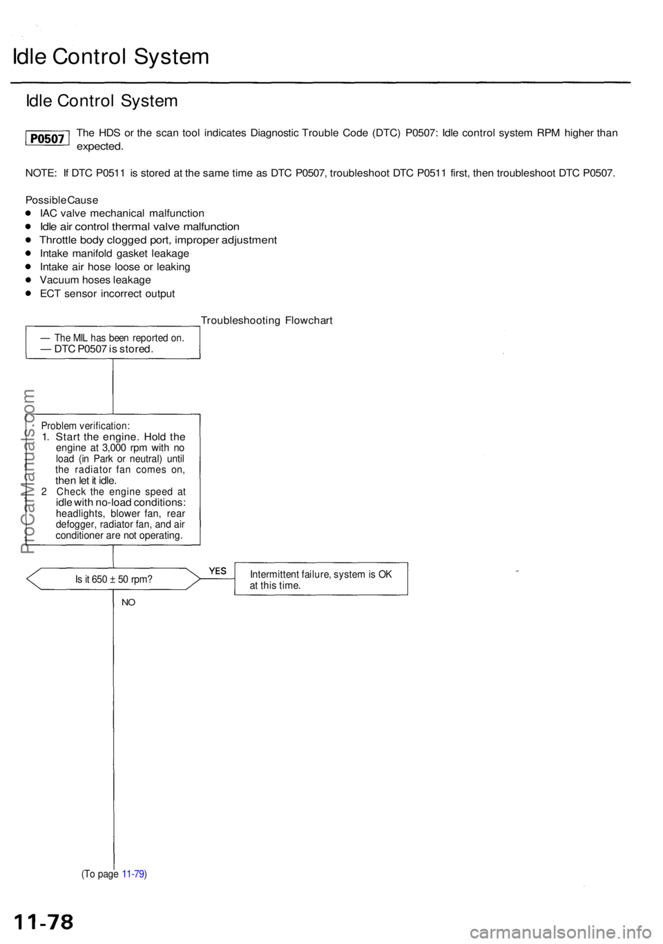
The HD S o r th e sca n too l indicate s Diagnosti c Troubl e Cod e (DTC ) P0507 : Idl e contro l syste m RP M highe r tha n
expected .
NOTE: I f DT C P051 1 i s store d a t th e sam e tim e a s DT C P0507 , troubleshoo t DT C P051 1 first , the n troubleshoo t DT C P0507 .
Possibl e Caus e
IA C valv e mechanica l malfunctio n
Idle ai r contro l therma l valv e malfunctio n
Throttle bod y clogge d port , imprope r adjustmen t
Intake manifol d gaske t leakag e
Intak e ai r hos e loos e o r leakin g
Vacuu m hose s leakag e
EC T senso r incorrec t outpu t
Troubleshootin g Flowchar t
— Th e MI L ha s bee n reporte d on .— DT C P050 7 is stored .
Problem verification :1. Star t th e engine . Hol d th eengin e a t 3,00 0 rp m wit h n oloa d (i n Par k o r neutral ) unti lthe radiato r fa n come s on ,then le t i t idle .2 Chec k th e engin e spee d a tidle wit h no-loa d conditions :headlights , blowe r fan , rea rdefogger , radiato r fan , an d ai rconditione r ar e no t operating .
Is it 65 0 ± 5 0 rpm ?Intermitten t failure , syste m is O Kat thi s time .
NO
(T o pag e 11-79 )
ProCarManuals.com
Page 612 of 1954
Idle Contro l Syste m
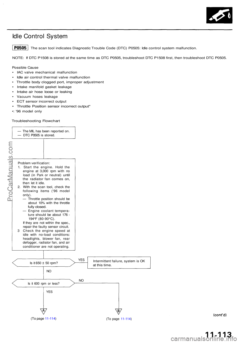
NOTE: I f DT C P150 8 is store d a t th e sam e tim e a s DT C P0505 , troubleshoo t DT C P150 8 first , the n troubleshoo t DT C P0505 .
Possibl e Caus e
• IA C valv e mechanica l malfunctio n
• Idl e ai r contro l therma l valv e malfunctio n
• Throttl e bod y clogge d port , imprope r adjustmen t
• Intak e manifol d gaske t leakag e
• Intak e ai r hos e loos e o r leakin g
• Vacuu m hose s leakag e
• EC T senso r incorrec t outpu t
• Throttl e Positio n senso r incorrec t output *
•: '9 6 mode l onl y
— Th e MI L ha s bee n reporte d on .
— DT C P050 5 is stored .
Proble m verification :
1 . Star t th e engine . Hol d th e
engin e a t 3,00 0 rp m wit h n o
loa d
(in Par k or neutral ) untilthe radiato r fa n come s on ,then le t i t idle .
2 . Wit h th e sca n tool , chec k th e
followin g item s ('9 6 mode l
only) .
— Throttl e positio n shoul d b e
abou t 10 % wit h th e throttl e
fully closed .— Engin e coolan t tempera -
tur e shoul d b e abou t 17 6 -
194° F (80-90°C) .
I f the y ar e no t withi n th e spec. ,
repai r th e fault y senso r circuit .
3 Chec k th e engin e spee d a t
idl e wit h no-loa d conditions :
headlights , blowe r fan , rea r
defogger , radiato r fan , an d ai r
conditione r ar e no t operating .
Is i t 65 0 5 0 rpm ?
NO
Is i t 60 0 rp m o r less ?
YES
Intermitten t failure , syste m is O Kat thi s time .
NO
(T o pag e 11-114 ) (T o pag e 11-114 )
YES
The sca n too l indicate s Diagnosti c Troubl e Cod e (DTC ) P0505 : Idl e contro l syste m malfunction .
Troubleshootin g Flowchar t
ProCarManuals.com
Page 617 of 1954
Idle Contro l Syste m
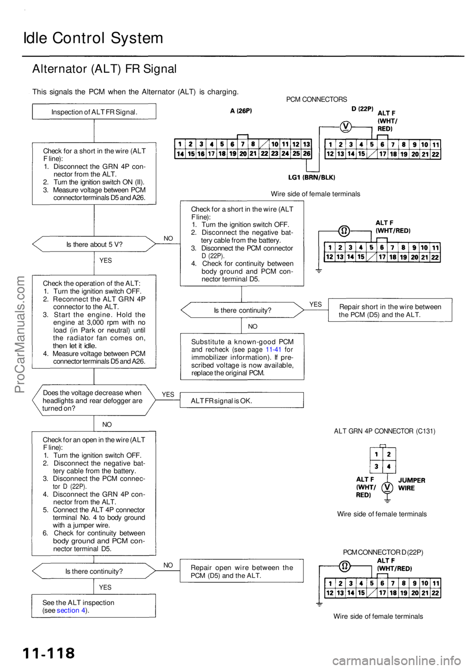
Alternato r (ALT ) F R Signa l
PCM CONNECTOR S
Is ther e abou t 5 V ?
YE S
Chec k th e operatio n o f th e ALT :
1 . Tur n th e ignitio n switc h OFF .
2 . Reconnec t th e AL T GR N 4 P
connecto r t o th e ALT .
3 . Star t th e engine . Hol d th e
engin e a t 3,00 0 rp m wit h n o
loa d (i n Par k o r neutral ) unti l
th e radiato r fa n come s on ,
then le t i t idle .4. Measur e voltag e betwee n PC M
connecto r terminal s D 5 an d A26 .
Doe s th e voltag e decreas e whe n
headlight s an d rea r defogge r ar e
turne d on ?
NO
Chec k fo r a n ope n in th e wir e (AL T
F line) :
1 . Tur n th e ignitio n switc h OFF .
2 . Disconnec t th e negativ e bat -
ter y cabl e fro m th e battery .
3 . Disconnec t th e PC M connec -
tor D (22P) .4. Disconnec t th e GR N 4 P con -
necto r fro m th e ALT .
5 . Connec t th e AL T 4 P connecto r
termina l No . 4 to bod y groun d
wit h a jumpe r wire .
6 . Chec k fo r continuit y betwee n
body groun d an d PC M con -necto r termina l D5 .
I s ther e continuity ?
YES
See th e AL T inspectio n
(see sectio n 4 ).
N O
Wir e sid e o f femal e terminal s
Chec k fo r a shor t i n th e wir e (AL T
F line) :
1 . Tur n th e ignitio n switc h OFF .
2 . Disconnec t th e negativ e bat -
ter y cabl e fro m th e battery .
3 . Disconnec t th e PC M connecto r
D (22P) .4. Chec k fo r continuit y betwee n
bod y groun d an d PC M con -
necto r termina l D5 .
I s ther e continuity ? Repai
r shor t i n th e wir e betwee n
the PC M (D5 ) and th e ALT .
NO
Substitut e a known-goo d PC Mand rechec k (se e pag e 11-4 1 fo rimmobilize r information) . I f pre -
scribe d voltag e is no w available ,
replac e th e origina l PCM .
AL T F R signa l i s OK .
ALT GR N 4 P CONNECTO R (C131 )
Repair ope n wir e betwee n th ePCM (D5 ) and th e ALT .
PCM CONNECTO R D (22P )
Wir e sid e o f femal e terminal s
NO
Wir e sid e o f femal e terminal s
YES YE
S
This signal s th e PC M whe n th e Alternato r (ALT ) i s charging .
Inspection o f AL T F R Signal .
Chec k fo r a shor t i n th e wir e (AL T
F line) :
1 . Disconnec t th e GR N 4 P con -
necto r fro m th e ALT .
2 . Tur n th e ignitio n switc h O N (II) .
3 . Measur e voltag e betwee n PC M
connecto r terminal s D 5 an d A26 .
ProCarManuals.com
Page 623 of 1954
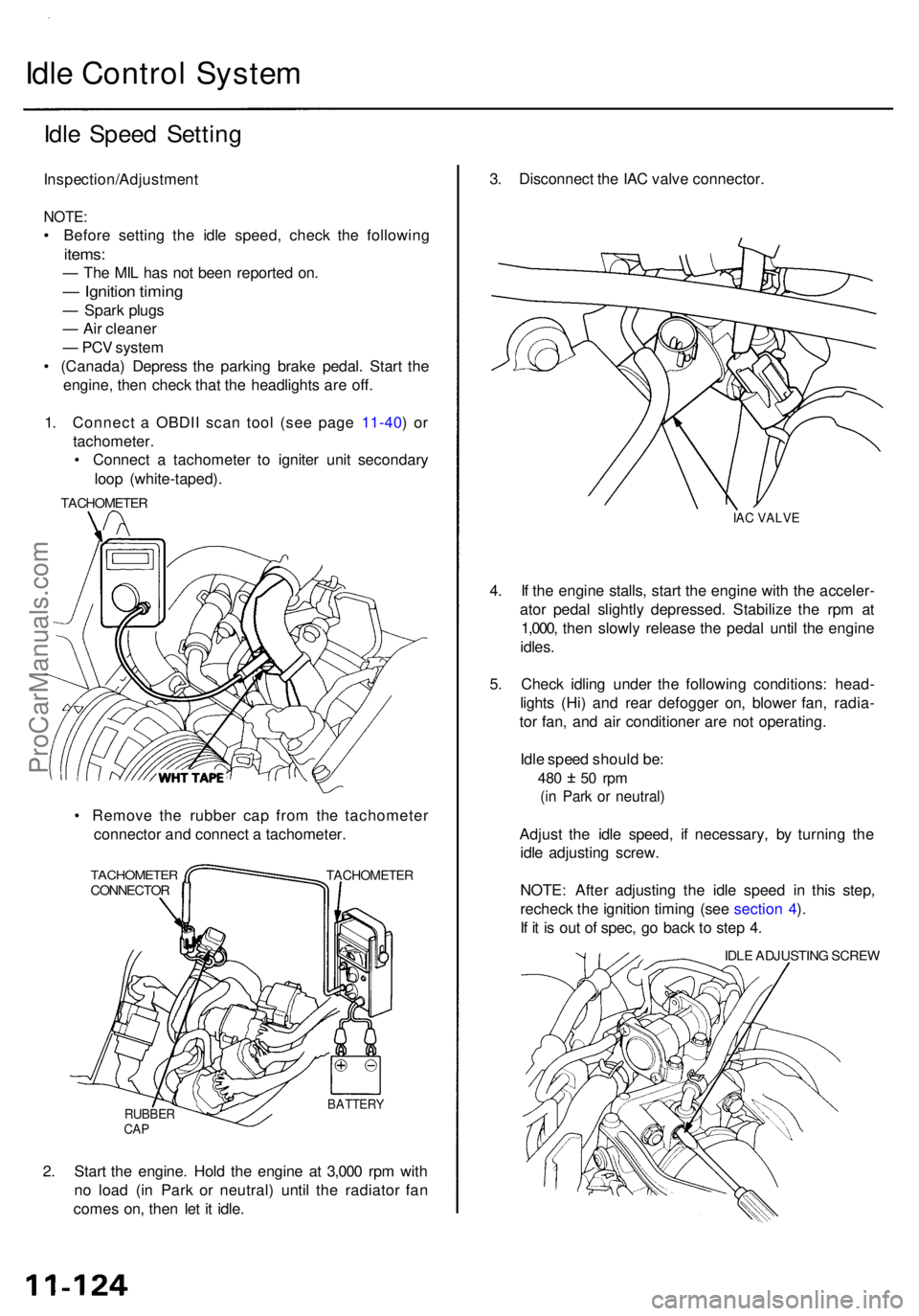
Idle Contro l Syste m
Idle Spee d Settin g
Inspection/Adjustmen t
NOTE:
• Befor e settin g th e idl e speed , chec k th e followin g
items:
— Th e MI L ha s no t bee n reporte d on .
— Ignitio n timin g
— Spar k plug s
— Ai r cleane r
— PC V syste m
• (Canada ) Depres s th e parkin g brak e pedal . Star t th e
engine , the n chec k tha t th e headlight s ar e off .
1 . Connec t a OBDI I sca n too l (se e pag e 11-40 ) o r
tachometer .
• Connec t a tachomete r t o ignite r uni t secondar y
loo p (white-taped) .
• Remov e th e rubbe r ca p fro m th e tachomete r
connecto r an d connec t a tachometer .
TACHOMETE RCONNECTORTACHOMETE R
RUBBERCAP
BATTER Y
2. Star t th e engine . Hol d th e engin e a t 3,00 0 rp m wit h
n o loa d (i n Par k o r neutral ) unti l th e radiato r fa n
come s on , the n le t i t idle . 3
. Disconnec t th e IA C valv e connector .
IAC VALV E
4. I f th e engin e stalls , star t th e engin e wit h th e acceler -
ato r peda l slightl y depressed . Stabiliz e th e rp m a t
1,000 , the n slowl y releas e th e peda l unti l th e engin e
idles .
5 . Chec k idlin g unde r th e followin g conditions : head -
light s (Hi ) an d rea r defogge r on , blowe r fan , radia -
to r fan , an d ai r conditione r ar e no t operating .
Idl e spee d shoul d be :
480 5 0 rp m
(in Par k o r neutral )
Adjust th e idl e speed , i f necessary , b y turnin g th e
idl e adjustin g screw .
NOTE : Afte r adjustin g th e idl e spee d i n thi s step ,
rechec k th e ignitio n timin g (se e sectio n 4 ).
I f i t i s ou t o f spec , g o bac k t o ste p 4 .
IDL E ADJUSTIN G SCRE W
TACHOMETE
R
ProCarManuals.com
Page 625 of 1954
PCM Memory Setting
NOTE: The PCM reset procedure and disconnecting the
battery or the BACK UP RADIO (7.5 A) fuse cancels the
PCM memory for idle control. The following procedure
is needed after the PCM reset procedure and reconnect-
ing the battery or the BACK UP RADIO (7.5 A) fuse.
1. Start the engine. Hold the engine at 3,000 rpm with
no load (in Park or neutral) until the radiator fan
comes on.
2. Let the engine idle for approx. 5 minutes under the
following conditions:
• Transmission in Park or neutral
• A/C switch OFF
• Headlights OFF
• Rear defogger OFFProCarManuals.com
Page 668 of 1954
Emission Contro l Syste m
System Descriptio n
The emissio n contro l syste m include s a Thre e Wa y Cata -
lyti c Converte r (TWC) , Exhaus t Ga s Recirculatio n (EGR )
system , Positiv e Crankcas e Ventilatio n (PCV ) syste m an d
Evaporativ e Emissio n (EVAP ) system . Th e emissio n contro l
syste m is designe d t o mee t federa l an d stat e emissio n
standards .
Tailpipe Emissio n
Inspection
Do no t smok e durin g thi s procedure . Kee p
an y ope n flam e awa y fro m you r wor k area .
1 . Star t th e engine . Hol d th e engin e a t 3,00 0 rp m wit h
n o loa d (i n Par k o r neutral ) unti l th e radiato r fa n
come s on , the n le t i t idle .
2 . Connec t a tachometer .
3 . Chec k an d adjus t th e idl e speed , i f necessar y (se e
pag e 11-124 ).
4 . War m u p an d calibrat e th e C O mete r accordin g to th e
mete r manufacturer' s instructions .
5 . Chec k idl e C O wit h th e headlights , heate r blower ,
rea r windo w defogger , coolin g fan , an d ai r condition -
er off .
NOTE : (Canada ) Depres s th e parkin g brak e pedal .
Star t th e engine , the n chec k tha t th e headlight s ar e
off.
CO mete r shoul d indicat e 0.1 % maximum .
Three Wa y Catalyti c Converte r
(TWC)
Descriptio n
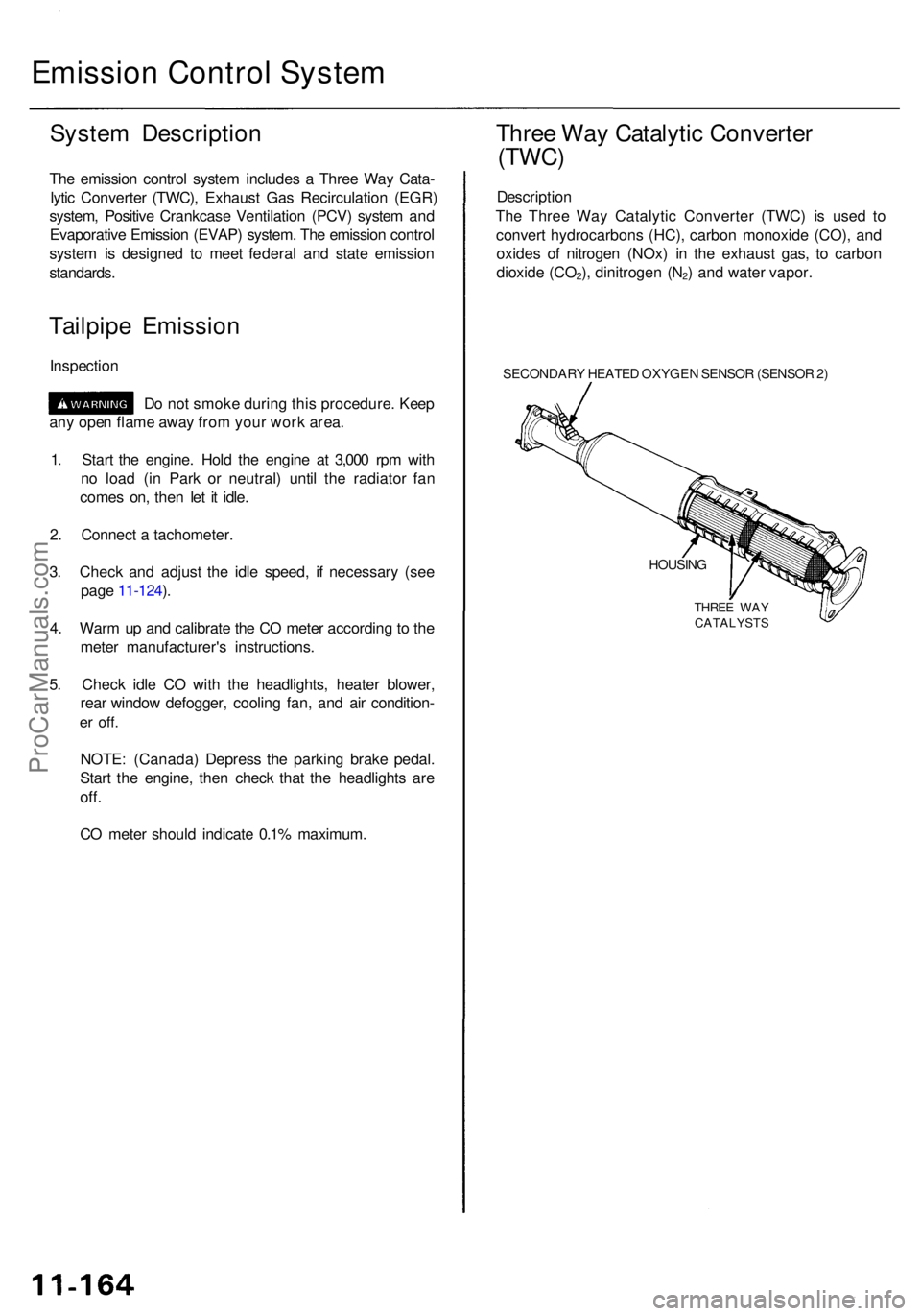
Th e Thre e Wa y Catalyti c Converte r (TWC) is use d t o
conver t hydrocarbon s (HC) , carbo n monoxid e (CO) , an d
oxide s o f nitroge n (NOx) in th e exhaus t gas , t o carbo n
dioxid e (CO
2), dinitroge n (N2) an d wate r vapor .
SECONDAR Y HEATE D OXYGE N SENSO R (SENSO R 2)
HOUSIN G
THREE WA Y
CATALYST S
ProCarManuals.com
Page 1517 of 1954
Power Relay s
Relay Tes t
NOTE : Se e pag e 23-13 2 fo r tur n signal/hazar d rela y inpu t
test .
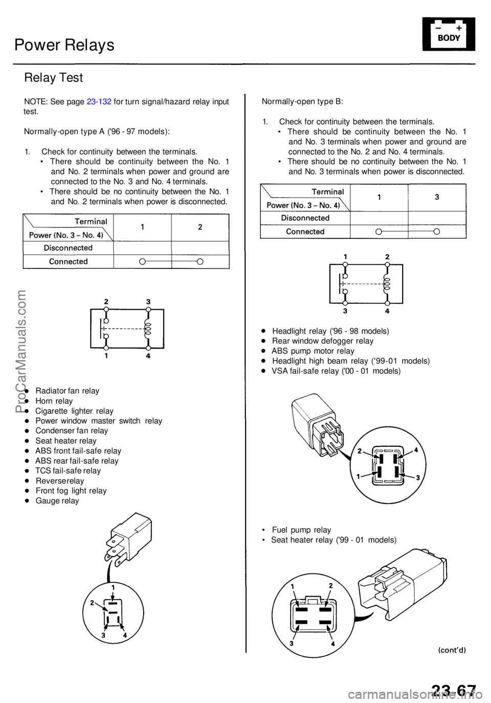
Normally-ope n typ e A ('9 6 - 9 7 models) :
1 . Chec k fo r continuit y betwee n th e terminals .
• Ther e shoul d b e continuit y betwee n th e No . 1
an d No . 2 terminal s whe n powe r an d groun d ar e
connecte d t o th e No . 3 an d No . 4 terminals .
• Ther e shoul d b e n o continuit y betwee n th e No . 1
an d No . 2 terminal s whe n powe r i s disconnected .Normally-ope
n typ e B :
1 . Chec k fo r continuit y betwee n th e terminals .
• Ther e shoul d b e continuit y betwee n th e No . 1
an d No . 3 terminal s whe n powe r an d groun d ar e
connecte d t o th e No . 2 an d No . 4 terminals .
• Ther e shoul d b e n o continuit y betwee n th e No . 1
an d No . 3 terminal s whe n powe r i s disconnected .
Radiato r fa n rela y
Hor n rela y
Cigarett e lighte r rela y
Powe r windo w maste r switc h rela y
Condense r fa n rela y
Sea t heate r rela y
AB S fron t fail-saf e rela y
AB S rea r fail-saf e rela y
TC S fail-saf e rela y
Revers e rela y
Fron t fo g ligh t rela y
Gaug e rela y
• Fue l pum p rela y
• Sea t heate r rela y ('9 9 - 0 1 models )
Headligh
t rela y ('9 6 - 9 8 models )
Rea r windo w defogge r rela y
AB S pum p moto r rela y
Headligh t hig h bea m rela y ('99-0 1 models )
VS A fail-saf e rela y ('0 0 - 0 1 models )
ProCarManuals.com
Page 1552 of 1954
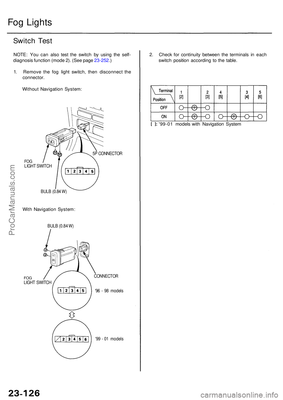
Fog Light s
Switch Tes t
NOTE : Yo u ca n als o tes t th e switc h b y usin g th e self -
diagnosi s functio n (mod e 2) . (Se e pag e 23-252 .)
1 . Remov e th e fo g ligh t switch , the n disconnec t th e
connector .
Withou t Navigatio n System :
FOGLIGH T SWITC H
BUL B (0.8 4 W ) 5
P CONNECTO R
With Navigatio n System : 2
. Chec k fo r continuit y betwee n th e terminal s i n eac h
switc h positio n accordin g t o th e table .
'99-0 1 model s wit h Navigatio n Syste m
BULB (0.8 4 W )
FO GLIGH T SWITC H
CONNECTO R
'96 - 9 8 model s
'9 9 - 0 1 model s
ProCarManuals.com
Page 1553 of 1954
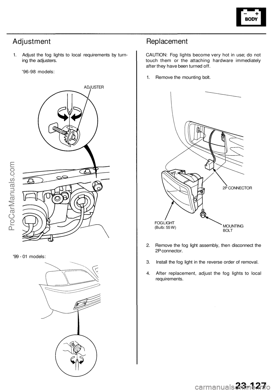
Adjustment
1. Adjus t th e fo g light s t o loca l requirement s b y turn -
ing th e adjusters .
'96-98 models :
ADJUSTE R
Replacemen t
CAUTION: Fo g light s becom e ver y ho t i n use ; d o no t
touc h the m o r th e attachin g hardwar e immediatel y
afte r the y hav e bee n turne d off .
1 . Remov e th e mountin g bolt .
2P CONNECTO R
MOUNTINGBOLT
FOG LIGH T
(Bulb : 5 5 W )
2. Remov e th e fo g ligh t assembly , the n disconnec t th e
2 P connector .
3 . Instal l th e fo g ligh t i n th e revers e orde r o f removal .
4 . Afte r replacement , adjus t th e fo g light s t o loca l
requirements .
'9
9 - 0 1 models :
ProCarManuals.com