check engine light ACURA RL KA9 1996 Service Repair Manual
[x] Cancel search | Manufacturer: ACURA, Model Year: 1996, Model line: RL KA9, Model: ACURA RL KA9 1996Pages: 1954, PDF Size: 61.44 MB
Page 345 of 1954
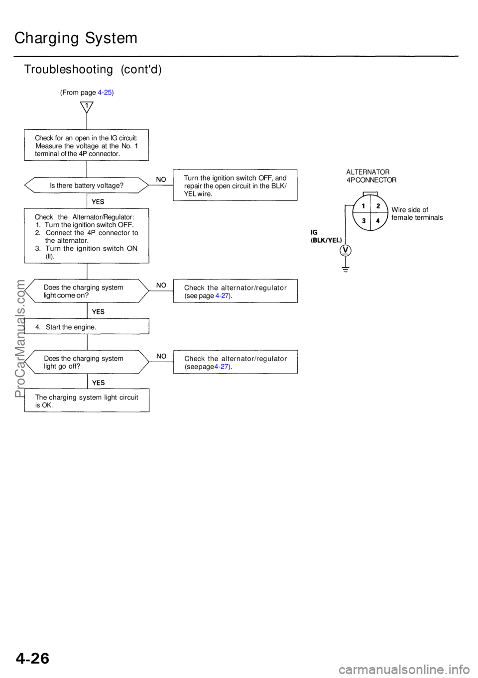
Charging Syste m
Troubleshootin g (cont'd )
(From page 4-25)
Chec k fo r a n ope n in th e IG circuit :
Measur e th e voltag e a t th e No . 1
termina l o f th e 4 P connector .
I s ther e batter y voltage ?
Chec k th e Alternator/Regulator :
1. Tur n th e ignitio n switc h OFF .2. Connec t th e 4 P connecto r t o
th e alternator .
3. Tur n th e ignitio n switc h O N(II).
Doe s th e chargin g syste mlight com e on ?
4. Star t th e engine .
Doe s th e chargin g syste m
ligh t g o off ?
Th e chargin g syste m ligh t circui t
is OK .
Turn th e ignitio n switc h OFF , an drepai r th e ope n circui t i n th e BLK /YEL wire .
ALTERNATO R4P CONNECTO R
Wir e sid e o f
femal e terminal s
Check th e alternator/regulato r
(se e pag e 4-27 ).
Chec k th e alternator/regulato r
(se e pag e 4-27 ).
ProCarManuals.com
Page 457 of 1954
Crankshaft
Installation (cont'd)
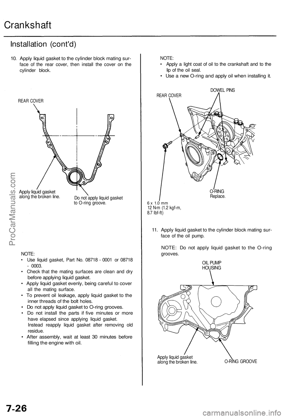
10. Apply liquid gasket to the cylinder block mating sur-
face of the rear cover, then install the cover on the
cylinder block.
REAR COVER
Apply liquid gasket
along the broken line.
Do not apply liquid gasket
to O-ring groove.
NOTE:
• Use liquid gasket, Part No. 08718 - 0001 or 08718
- 0003.
• Check that the mating surfaces are clean and dry
before applying liquid gasket.
• Apply liquid gasket evenly, being careful to cover
all the mating surface.
• To prevent oil leakage, apply liquid gasket to the
inner threads of the bolt holes.
• Do not apply liquid gasket to O-ring grooves.
• Do not install the parts if five minutes or more
have elapsed since applying liquid gasket.
Instead reapply liquid gasket after removing old
residue.
• After assembly, wait at least 30 minutes before
filling the engine with oil.
Apply liquid gasket
along the broken line.
O-RING GROOVE
NOTE:
• Apply a light coat of oil to the crankshaft and to the
lip of the oil seal.
• Use a new O-ring and apply oil when installing it.
REAR COVER
DOWEL PINS
6 x 1.0 mm
12 N-m (1.2 kgf-m,
8.7 Ibf-ft)
O-RING
Replace.
11. Apply liquid gasket to the cylinder block mating sur-
face of the oil pump.
NOTE: Do not apply liquid gasket to the O-ring
grooves.
OIL PUMP
HOUSINGProCarManuals.com
Page 728 of 1954
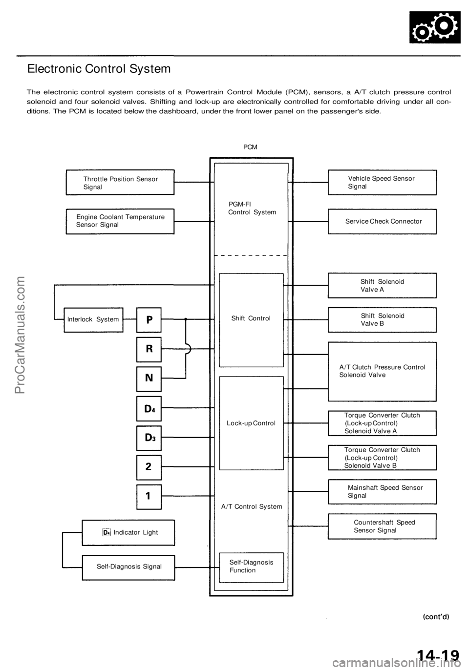
Electronic Control System
The electronic control system consists of a Powertrain Control Module (PCM), sensors, a A/T clutch pressure control
solenoid and four solenoid valves. Shifting and lock-up are electronically controlled for comfortable driving under all con-
ditions. The PCM is located below the dashboard, under the front lower panel on the passenger's side.
PCM
Throttle Position Sensor
Signal
Engine Coolant Temperature
Sensor Signal
Indicator Light
Self-Diagnosis Signal
PGM-FI
Control System
Shift Control
Lock-up Control
A/T Control System
Self-Diagnosis
Function
Vehicle Speed Sensor
Signal
Service Check Connector
Shift Solenoid
Valve A
Shift Solenoid
Valve B
A/T Clutch Pressure Control
Solenoid Valve
Torque Converter Clutch
(Lock-up Control)
Solenoid Valve A
Torque Converter Clutch
(Lock-up Control)
Solenoid Valve B
Mainshaft Speed Sensor
Signal
Countershaft Speed
Sensor Signal
Interlock SystemProCarManuals.com
Page 802 of 1954
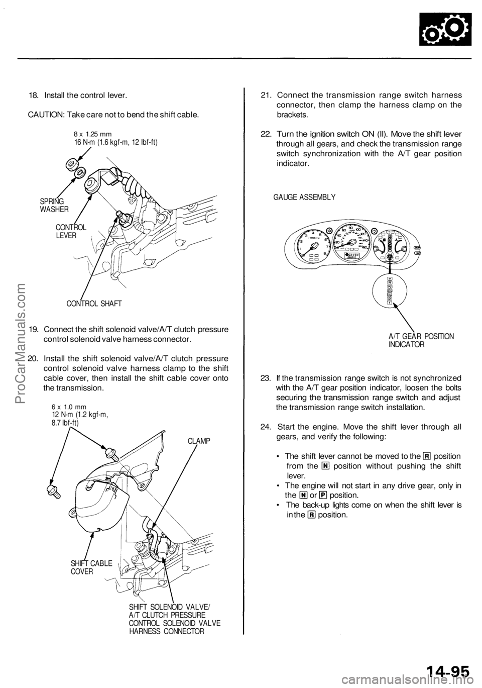
18. Install the control lever.
CAUTION: Take care not to bend the shift cable.
SPRING
WASHER
CONTROL SHAFT
19. Connect the shift solenoid valve/A/T clutch pressure
control solenoid valve harness connector.
20. Install the shift solenoid valve/A/T clutch pressure
control solenoid valve harness clamp to the shift
cable cover, then install the shift cable cover onto
the transmission.
CLAMP
SHIFT CABLE
COVER
SHIFT SOLENOID VALVE/
A/T CLUTCH PRESSURE
CONTROL SOLENOID VALVE
HARNESS CONNECTOR
21. Connect the transmission range switch harness
connector, then clamp the harness clamp on the
brackets.
22. Turn the ignition switch ON (II). Move the shift lever
through all gears, and check the transmission range
switch synchronization with the A/T gear position
indicator.
GAUGE ASSEMBLY
A/T GEAR POSITION
INDICATOR
23. If the transmission range switch is not synchronized
with the A/T gear position indicator, loosen the bolts
securing the transmission range switch and adjust
the transmission range switch installation.
24. Start the engine. Move the shift lever through all
gears, and verify the following:
• The shift lever cannot be moved to the position
from the position without pushing the shift
lever.
• The engine will not start in any drive gear, only in
the or position.
• The back-up lights come on when the shift lever is
in the position.
8 x
1.25
mm
16 N-m (1.6 kgf-m, 12 Ibf-ft)
CONTROL
LEVER
6 x 1.0 mm
12 N-m (1.2 kgf-m,
8.7 Ibf-ft)ProCarManuals.com
Page 1051 of 1954
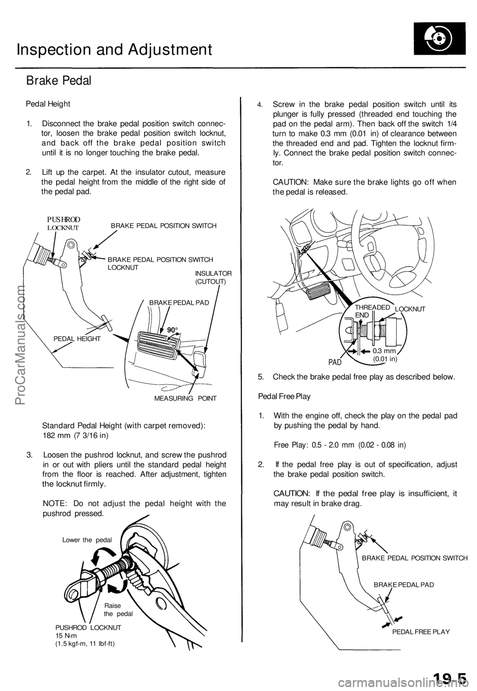
Inspection and Adjustment
Brake Pedal
Pedal Height
1. Disconnect the brake pedal position switch connec-
tor, loosen the brake pedal position switch locknut,
and back off the brake pedal position switch
until it is no longer touching the brake pedal.
2.
Lift up the carpet. At the insulator cutout, measure
the pedal height from the middle of the right side of
the pedal pad.
PUSHROD
LOCKNUT
BRAKE PEDAL POSITION SWITCH
BRAKE PEDAL POSITION SWITCH
LOCKNUT
INSULATOR
(CUTOUT)
MEASURING POINT
Standard Pedal Height (with carpet removed):
182 mm (7
3/16
in)
3. Loosen the pushrod locknut, and screw the pushrod
in or out with pliers until the standard pedal height
from the floor is reached. After adjustment, tighten
the locknut firmly.
NOTE: Do not adjust the pedal height with the
pushrod pressed.
Lower the pedal
PUSHROD LOCKNUT
15 N-m
(1.5 kgf-m, 11 Ibf-ft)
4.
Screw in the brake pedal position switch until its
plunger is fully pressed (threaded end touching the
pad on the pedal arm). Then back off the switch 1/4
turn to make 0.3 mm (0.01 in) of clearance between
the threaded end and pad. Tighten the locknut firm-
ly. Connect the brake pedal position switch connec-
tor.
CAUTION: Make sure the brake lights go off when
the pedal is released.
PAD
5. Check the brake pedal free play as described below.
Pedal Free Play
1. With the engine off, check the play on the pedal pad
by pushing the pedal by hand.
Free Play: 0.5 - 2.0 mm (0.02 - 0.08 in)
2. If the pedal free play is out of specification, adjust
the brake pedal position switch.
CAUTION: If the pedal free play is insufficient, it
may result in brake drag.
BRAKE PEDAL POSITION SWITCH
BRAKE PEDAL PAD
PEDAL FREE PLAY
LOCKNUT
THREADED
END
0.3 mm
(0.01
in)
BRAKE PEDAL PAD
PEDAL HEIGHT
Raise
the pedalProCarManuals.com
Page 1084 of 1954
Troubleshooting Precautions
ABS Indicator Light:
The ABS indicator light comes on for 3 seconds and then goes off when the control unit detects no problem during the ini-
tial diagnosis right after the engine starts. However, the ABS indicator light can stay on for up to 40 seconds when the
control unit starts to check for pump overrun, etc. during the initial diagnosis. The ABS indicator light comes on, and the
ABS control unit memorizes the diagnostic trouble code (DTC) under certain conditions.
The parking brake is applied for more than 30 seconds while the vehicle is being driven. (DTC 2-1)
The transmission downshifted excessively. (DTC 4-1, 4-2)
The vehicle loses traction, and the front wheels spin for more than 1 minute when starting from a stuck condition on a
muddy, snowy, or sandy road. (DTC 4-8)
Tire adhesion is lost due to excessive cornering speed. (DTC 5, 5-4, 5-8)
The vehicle is driven on an extremely rough road. (DTC 8-1)
The vehicle is interfered by strong radio waves (noise), for example, illegal radio, etc. (DTC 8-2)
NOTE: If there is any trouble in the system, the ABS indicator light comes on during driving.
Diagnostic Trouble Code (DTC):
When the control unit detects a problem and the ABS indicator light comes on, the control unit memorizes the DTC.
The control unit has three memory registers. When a problem occurs, the control unit stores the DTC in the first memory
register. If another problem occurs, or the same problem occurs again, the control unit moves the first DTC to the next
memory register, and stores the second DTC in the first register. If there's a third problem occurrence, the two existing
DTCs are moved up one register, and the third DTC is stored in the first register. If problems continue to occur, the oldest
problem is moved out of the last register and lost, and the most recent problem is stored in the first register. When the
same problem occurs three times, the same DTC is stored in all memory registers. (Refer to the Symptom-to-System
Chart for diagnostic period.)
The most recent DTC is indicated first, and the oldest DTC is indicated last.
The DTCs are erased from the control unit when the ABS control unit +B2 power supply or connector is disconnected.
The control unit's memory can be erased by disconnecting the ABS B2 fuse for more than 3 seconds.
Self-diagnosis:
There are three self-diagnoses described below.
Initial diagnosis: Performed right after the engine starts until the ABS indicator light goes off.
Regular diagnosis: Continuously performed (under some conditions) after the ABS indicator light goes off until the
engine stops.
Individual part/system diagnosis: Diagnosis about a specific part/system under its operating conditions.
The CPU (central processing unit) controls the following when it detects a problem during self-diagnosis:
Turns the ABS indicator light ON.
Turns the front and rear fail-safe relays off.
Stops the ABS control.
Stops the ABS pump. (The pump may work under some conditions.)
After the DTC is stored in the control unit, the CPU stops self-diagnosis.ProCarManuals.com
Page 1087 of 1954
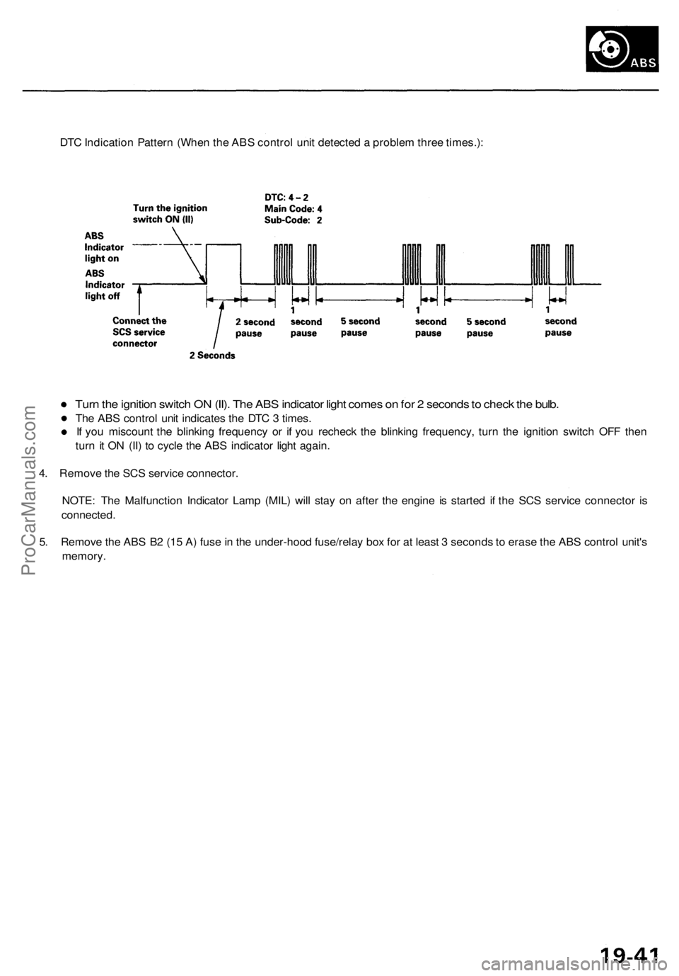
DTC Indication Pattern (When the ABS control unit detected a problem three times.):
Turn the ignition switch ON (II). The ABS indicator light comes on for 2 seconds to check the bulb.
The ABS control unit indicates the DTC 3 times.
If you miscount the blinking frequency or if you recheck the blinking frequency, turn the ignition switch OFF then
turn it ON (II) to cycle the ABS indicator light again.
4. Remove the SCS service connector.
NOTE: The Malfunction Indicator Lamp (MIL) will stay on after the engine is started if the SCS service connector is
connected.
5. Remove the ABS B2 (15 A) fuse in the under-hood fuse/relay box for at least 3 seconds to erase the ABS control unit's
memory.ProCarManuals.com
Page 1091 of 1954
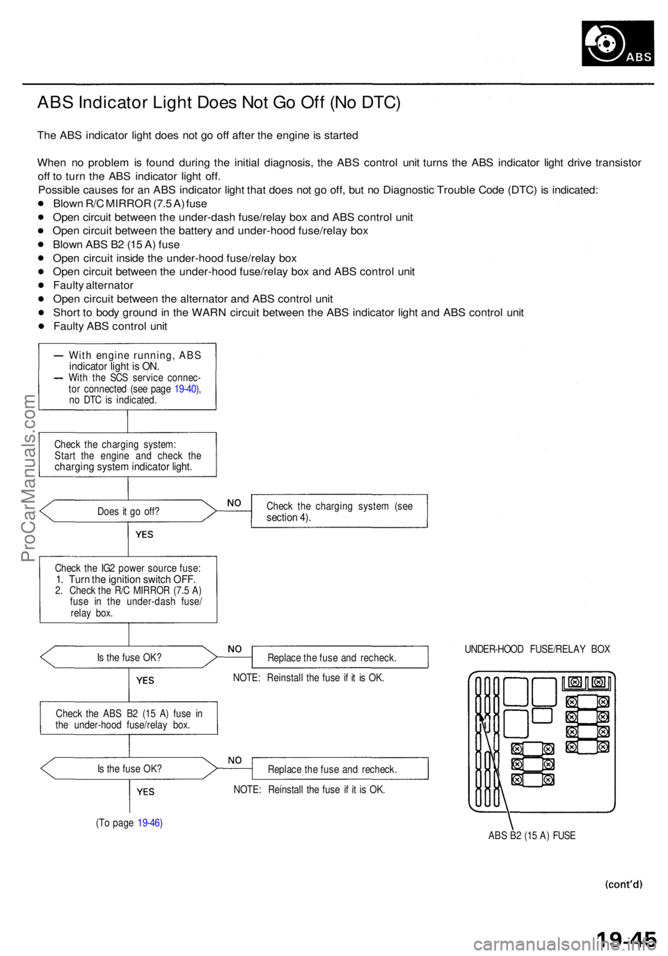
ABS Indicato r Ligh t Doe s No t G o Of f (N o DTC )
The AB S indicato r ligh t doe s no t g o of f afte r th e engine is starte d
Whe n n o proble m is foun d durin g th e initia l diagnosis , th e AB S contro l uni t turn s th e AB S indicato r ligh t driv e transisto r
of f t o tur n th e AB S indicato r ligh t off .
Possibl e cause s fo r a n AB S indicato r ligh t tha t doe s no t g o off , bu t n o Diagnosti c Troubl e Cod e (DTC ) i s indicated :
Blow n R/ C MIRRO R (7. 5 A ) fus e
Ope n circui t betwee n th e under-das h fuse/rela y bo x an d AB S contro l uni t
Ope n circui t betwee n th e batter y an d under-hoo d fuse/rela y bo x
Blow n AB S B 2 (1 5 A ) fus e
Ope n circui t insid e th e under-hoo d fuse/rela y bo x
Ope n circui t betwee n th e under-hoo d fuse/rela y bo x an d AB S contro l uni t
Fault y alternato r
Ope n circui t betwee n th e alternato r an d AB S contro l uni t
Shor t t o bod y groun d in th e WAR N circui t betwee n th e AB S indicator light an d AB S contro l uni t
Fault y AB S contro l uni t
Wit h engin e running , AB Sindicato r ligh t i s ON .With th e SC S servic e connec -
to r connecte d (se e pag e 19-40 ),
n o DT C is indicated .
Chec k th e chargin g system :
Star t th e engin e an d chec k th e
chargin g syste m indicato r light .
Does i t g o off ?
Chec k th e IG 2 powe r sourc e fuse :
1. Tur n th e ignitio n switc h OFF .2. Chec k th e R/ C MIRRO R (7. 5 A )
fus e i n th e under-das h fuse /
rela y box .
I s th e fus e OK ?
Chec k th e AB S B 2 (1 5 A ) fus e i n
th e under-hoo d fuse/rela y box .
I s th e fus e OK ?
(T o pag e 19-46 ) Chec
k th e chargin g syste m (se e
sectio n 4) .
Replac e th e fus e an d recheck . UNDER-HOO
D FUSE/RELA Y BO X
NOTE : Reinstal l th e fus e i f i t i s OK .
Replac e th e fus e an d recheck .
NOTE : Reinstal l th e fus e i f i t i s OK .
ABS B 2 (1 5 A ) FUS E
ProCarManuals.com
Page 1196 of 1954

TCS CONTROL UNIT 20P CONNECTOR
Wire side of female terminals
VB: Battery Voltage
Terminal
number
1
2
4
5
6
9
10
11
12
13
14
15
16
17
20
Wire
color
BLK/YEL
GRN/RED
BLU
PNK/BLU
BLK/WHT
BLK
BRN/WHT
GRN/WHT
BLU
GRN/ORN
BLK/ORN
BRN/BLK
WHT/BLU
BLU/GRY
GRN
BRN
Terminal sign
(Terminal name)
IG1
(Ignition 1)
PARK
(Parking)
SCS
(Service check
signal)
STR-GND
(Steering ground)
AT-SHIFT
(AT shift)
FSR
(Fail-safe relay)
PMG
(Power motor
Ground)
VPM
(Voltage power
motor)
STOP
(Stop)
NEP (Engine
speed pulse)
BARO
(Barometric)
TC-FC
(Traction control
fuel cut)
LG2
(Logic ground 2)
STR-VCC (Steer-
ing power supply)
WARN2
(Warning 2)
SH-MOT
(Shield motor)
MOT +
(Motor +)
MOT-
(Motor -)
Description
Detects ignition switch
IG1 signal
Detects parking brake
switch signal
Detects service check
connector signal
(Diagnostic trouble
code indication)
Ground for the steering
angle sensor
Detects A/T shift posi-
tion signal
Drives fail-safe relay
Power ground for the
TCS control valve
actuator motor
Power source for the
TCS control valve
actuator motor
Detects brake pedal
position switch signal
Detects engine speed
signal
Detects barometric
sensor signal
TCS Fl, Fuel cut
(torque down) signal
Ground for the logic
circuit
Power source for the
steering angle sensor
Drives TCS indicator light
(The indicator light comes
on by the self-bias)
Shield for the TCS con-
trol valve actuator motor
Drives TCS control
valve actuator motor
Drives TCS control
valve actuator motor
Measurement
terminals
1-GND
2
3-GND
4-GND
5-GND
6-GND
9-GND
10-GND
11-GND
12-GND
13-GND
14-GND
15-GND
16-GND
17-GND
19-20
20-19
Voltage
Conditions
(Ignition Switch ON (II))
Depress the parking
brake pedal.
Release the parking
brake pedal.
SCS service connector
connected.
SCS service connector
disconnected.
Shift the transmission
to position, then
start the engine.
Start the engine.
Start the engine.
Brake pedal depressed.
Brake pedal released.
Engine idling
TCS is functioning,
(maximum fuel cut)
TCS is not functioning.
Indicator light ON
Indicator light OFF
TCS is functioning.
TCS is not functioning.
TCS is functioning.
TCS is not functioning.
Output
voltage
VB
Below 0.6 V
VB
0V
5V
Below 0.3V
About 4V
(5V 0V)
VB
1.5V
Below 0.3 V
0V
VB
VB
0V
About 6V
(12V
0V)
About 3 V
About 1.5V
About 4.5 V
(5 V,
PWM)
Below 0.3V
About 5 V
About 2 V
VB
VB
0V
VB
0VProCarManuals.com
Page 1212 of 1954
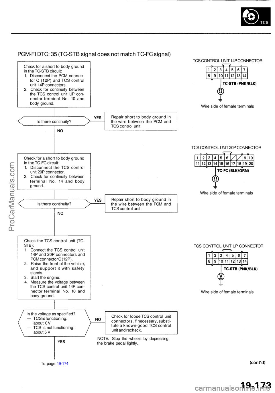
PGM-FI DTC : 3 5 (TC-ST B signa l doe s no t matc h TC-F C signal )
Check fo r a shor t t o bod y groun d
i n th e TC-ST B circuit :
1 . Disconnec t th e PC M connec -
to r C (12P ) an d TC S contro l
uni t 14 P connectors .
2 . Chec k fo r continuit y betwee n
th e TC S contro l uni t U P con -
necto r termina l No . 1 0 an d
bod y ground . TC
S CONTRO L UNI T 14 P CONNECTO R
Wir e sid e o f femal e terminal s
I s ther e continuity ? Repai
r shor t t o bod y groun d in
th e wir e betwee n th e PC M an d
TC S contro l unit .
TCS CONTRO L UNI T 20 P CONNECTO R
Chec k fo r a shor t t o bod y groun d
i n th e TC-F C circuit :
1 . Disconnec t th e TC S contro l
uni t 20 P connector .
2 . Chec k fo r continuit y betwee n
termina l No . 1 4 an d bod y
ground .
Is ther e continuity ?Repair shor t t o bod y groun d in
th e wir e betwee n th e PC M an d
TC S contro l unit . Wir
e sid e o f femal e terminal s
Chec k th e TC S contro l uni t (TC -
STB) :1. Connec t th e TC S contro l uni t
14 P an d 20 P connector s an d
PC M connecto r C (12P) .
2 . Rais e th e fron t o f th e vehicle ,
and suppor t i t wit h safet ystands.
3 . Star t th e engine .
4 . Measur e th e voltag e betwee n
th e TC S contro l uni t 14 P con -
necto r termina l No . 1 0 an d
bod y ground . TC
S CONTRO L UNI T U P CONNECTO R
Wir e sid e o f femal e terminal s
I s th e voltag e a s specified ?
TCS is functioning :about 0 V
TC S is no t functioning :
abou t 5 V Chec
k fo r loos e TC S contro l uni t
connectors . I f necessary , substi -
tut e a known-goo d TC S contro l
uni t an d recheck .
To pag e 19-17 4
NOTE : Sto p th e wheel s b y depressin g
th e brak e peda l lightly .
ProCarManuals.com