dlc ACURA RL KA9 1996 Service Repair Manual
[x] Cancel search | Manufacturer: ACURA, Model Year: 1996, Model line: RL KA9, Model: ACURA RL KA9 1996Pages: 1954, PDF Size: 61.44 MB
Page 163 of 1954
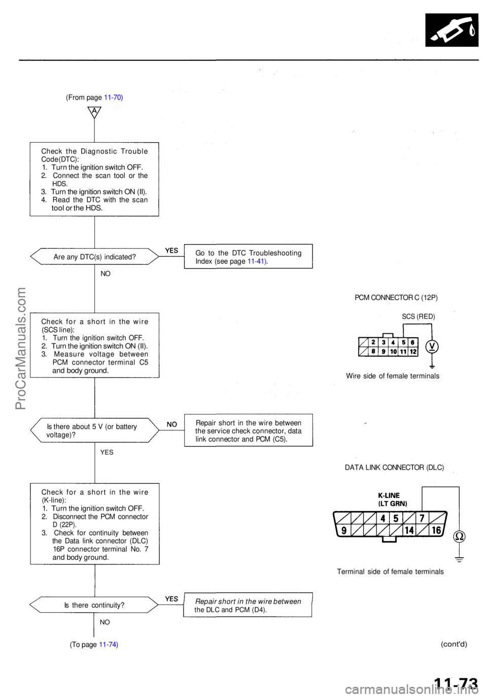
Check th e Diagnosti c Troubl e
Cod e (DTC) :
1. Tur n th e ignitio n switc h OFF .2. Connec t th e sca n too l o r th eHDS .3. Tur n th e ignitio n switc h O N (II) .4. Rea d th e DT C wit h th e sca ntool o r th e HDS .
Are an y DTC(s ) indicated ? G
o t o th e DT C Troubleshootin g
Inde x (se e pag e 11-41) .
NO
Chec k fo r a shor t i n th e wir e
(SC S line) :
1 . Tur n th e ignitio n switc h OFF .
2. Tur n th e ignitio n switc h O N (II) .3. Measur e voltag e betwee n
PC M connecto r termina l C 5
and bod y ground .
PCM CONNECTO R C (12P )
SCS (RED )
Wire sid e o f femal e terminal s
I s ther e abou t 5 V (o r batter y
voltage) ?
Repair shor t i n th e wir e betwee n
th e servic e chec k connector , dat a
lin k connecto r an d PC M (C5) .
YES
DAT A LIN K CONNECTO R (DLC )
Termina l sid e o f femal e terminal s
I s ther e continuity ? Repair
short in the wire between
the DL C an d PC M (D4) .
NO
(T o pag e 11-74 )(cont'd )
(From pag e 11-70 )
Chec k fo r a shor t i n th e wir e
(K-line) :1. Tur n th e ignitio n switc h OFF .2. Disconnec t th e PC M connecto rD (22P) .3. Chec k fo r continuit y betwee n
th e Dat a lin k connecto r (DLC )
16 P connecto r termina l No . 7
an d bod y ground .
ProCarManuals.com
Page 504 of 1954
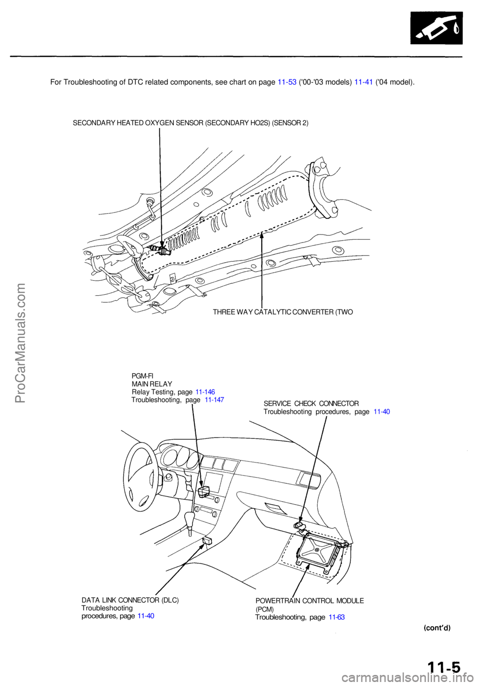
SECONDARY HEATE D OXYGE N SENSO R (SECONDAR Y HO2S ) (SENSO R 2 )
THRE E WA Y CATALYTI C CONVERTE R (TW O
PGM-F I
MAI N RELA Y
Rela y Testing , pag e 11-14 6
Troubleshooting , pag e 11-14 7
DAT A LIN K CONNECTO R (DLC )
Troubleshootin gprocedures, pag e 11-4 0
SERVIC E CHEC K CONNECTO R
Troubleshootin g procedures , pag e 11-4 0
POWERTRAI N CONTRO L MODUL E
(PCM)Troubleshooting , pag e 11-6 3
For Troubleshooting of DTC related components, see chart on page 11-53 ('00-'03 models) 11-41 ('04 model).
ProCarManuals.com
Page 539 of 1954
Troubleshooting
Troubleshooting Procedure s
I. Ho w T o Begi n Troubleshootin g
Whe n th e Malfunctio n Indicato r Lam p (MIL ) ha s bee n reporte d on , o r ther e i s a driveabilit y problem , us e th e appropri -
at e procedur e belo w to diagnos e an d repai r th e problem .
A . Whe n th e MI L ha s com e on :
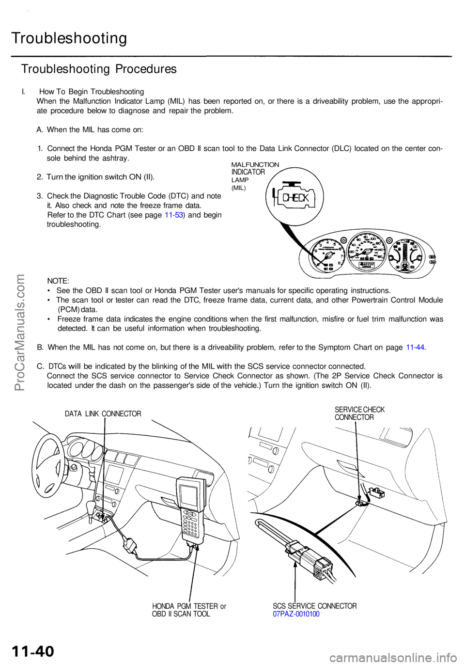
1 . Connec t th e Hond a PG M Teste r o r a n OB D II sca n too l t o th e Dat a Lin k Connecto r (DLC ) locate d o n th e cente r con -
sol e behin d th e ashtray .
MALFUNCTIO NINDICATORLAMP
(MIL )2. Tur n th e ignitio n switc h O N (II) .
3. Chec k th e Diagnosti c Troubl e Cod e (DTC ) an d not e
it . Als o chec k an d not e th e freez e fram e data .
Refe r t o th e DT C Char t (se e pag e 11-53 ) an d begi n
troubleshooting .
NOTE:
• Se e th e OB D II sca n too l o r Hond a PG M Teste r user' s manual s fo r specifi c operatin g instructions .
• Th e sca n too l o r teste r can read th e DTC , freez e fram e data , curren t data , an d othe r Powertrai n Contro l Modul e
(PCM ) data .
• Freez e fram e dat a indicate s th e engin e condition s whe n th e firs t malfunction , misfir e o r fue l tri m malfunctio n wa s
detected . I t ca n b e usefu l informatio n whe n troubleshooting .
B . Whe n th e MI L ha s no t com e on , bu t ther e i s a driveabilit y problem , refe r t o th e Sympto m Char t o n pag e 11-44 .
C. DTC s will be indicate d by th e blinkin g of th e MI L wit h the SC S servic e connecto r connected .
Connec t th e SC S servic e connecto r t o Servic e Chec k Connecto r a s shown . (Th e 2 P Servic e Chec k Connecto r i s
locate d unde r th e das h o n th e passenger' s sid e o f th e vehicle. ) Tur n th e ignitio n switc h O N (II) .
SERVIC E CHEC K
CONNECTO R
DAT
A LIN K CONNECTO R
SCS SERVIC E CONNECTO R
07PAZ-001010 0HONDA PG M TESTE R o r
OB D II SCA N TOO L
ProCarManuals.com
Page 544 of 1954
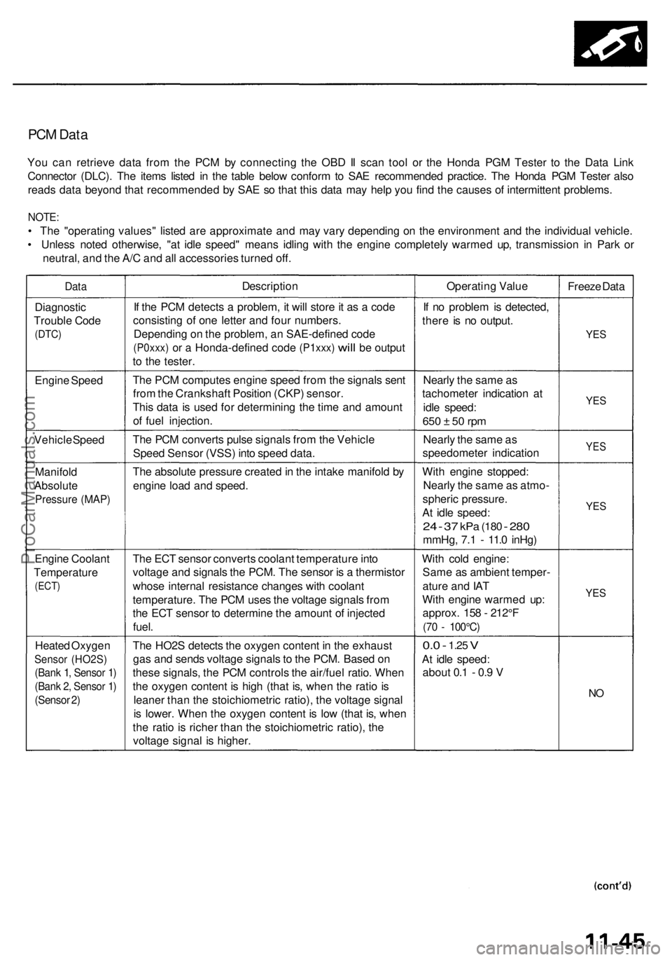
PCM Data
You can retrieve data from the PCM by connecting the OBD II scan tool or the Honda PGM Tester to the Data Link
Connector (DLC). The items listed in the table below conform to SAE recommended practice. The Honda PGM Tester also
reads data beyond that recommended by SAE so that this data may help you find the causes of intermittent problems.
NOTE:
• The "operating values" listed are approximate and may vary depending on the environment and the individual vehicle.
• Unless noted otherwise, "at idle speed" means idling with the engine completely warmed up, transmission in Park or
neutral, and the A/C and all accessories turned off.
Data
Description
Operating Value
Freeze Data
Diagnostic
Trouble Code
(DTC)
If the PCM detects a problem, it will store it as a code
consisting of one letter and four numbers.
Depending on the problem, an SAE-defined code
(P0xxx)
or a
Honda-defined code
(P1xxx)
will
be
output
to the tester.
If no problem is detected,
there is no output.
YES
Engine Speed
The PCM computes engine speed from the signals sent
from the Crankshaft Position (CKP) sensor.
This data is used for determining the time and amount
of fuel injection.
Nearly the same as
tachometer indication at
idle speed:
650 ± 50 rpm
YES
Vehicle Speed
The PCM converts pulse signals from the Vehicle
Speed Sensor (VSS) into speed data.
Nearly the same as
speedometer indication
YES
Manifold
Absolute
Pressure (MAP)
The absolute pressure created in the intake manifold by
engine load and speed.
With engine stopped:
Nearly the same as atmo-
spheric pressure.
At idle speed:
24 - 37
kPa
(180
-
280
mmHg, 7.1 - 11.0 inHg)
YES
Engine Coolant
Temperature
(ECT)
The ECT sensor converts coolant temperature into
voltage and signals the PCM. The sensor is a thermistor
whose internal resistance changes with coolant
temperature. The PCM uses the voltage signals from
the ECT sensor to determine the amount of injected
fuel.
With cold engine:
Same as ambient temper-
ature and IAT
With engine warmed up:
approx. 158 - 212°F
(70 - 100°C)
YES
Heated Oxygen
Sensor (HO2S)
(Bank 1, Sensor 1)
(Bank 2, Sensor 1)
(Sensor 2)
The HO2S detects the oxygen content in the exhaust
gas and sends voltage signals to the PCM. Based on
these signals, the PCM controls the air/fuel ratio. When
the oxygen content is high (that is, when the ratio is
leaner than the stoichiometric ratio), the voltage signal
is lower. When the oxygen content is low (that is, when
the ratio is richer than the stoichiometric ratio), the
voltage signal is higher.
0.0 -
1.25
V
At idle speed:
about 0.1 - 0.9 V
NOProCarManuals.com
Page 560 of 1954
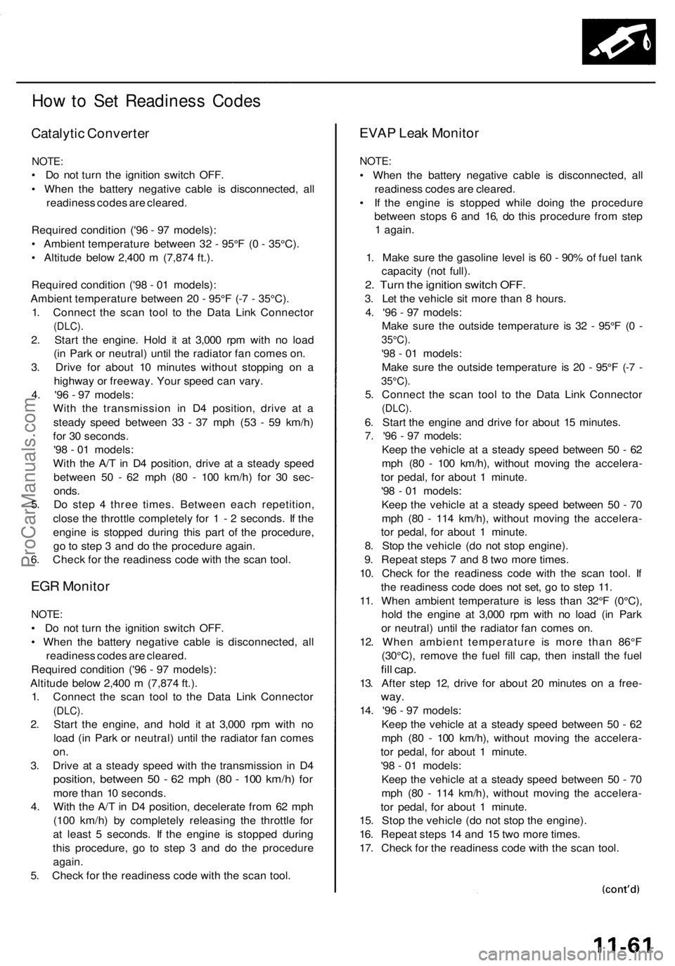
How to Set Readiness Codes
Catalytic Converter
NOTE:
• Do not turn the ignition switch OFF.
• When the battery negative cable is disconnected, all
readiness codes are cleared.
Required condition ('96 - 97 models):
• Ambient temperature between 32 - 95°F (0 - 35°C).
• Altitude below 2,400 m (7,874 ft.).
Required condition ('98 - 01 models):
Ambient temperature between 20 - 95°F (-7 - 35°C).
1. Connect the scan tool to the Data Link Connector
(DLC).
2. Start the engine. Hold it at 3,000 rpm with no load
(in Park or neutral) until the radiator fan comes on.
3. Drive for about 10 minutes without stopping on a
highway or freeway. Your speed can vary.
4. '96 - 97 models:
With the transmission in D4 position, drive at a
steady speed between 33 - 37 mph (53 - 59 km/h)
for 30 seconds.
'98 - 01 models:
With the A/T in D4 position, drive at a steady speed
between 50 - 62 mph (80 - 100 km/h) for 30 sec-
onds.
5. Do step 4 three times. Between each repetition,
close the throttle completely for 1 - 2 seconds. If the
engine is stopped during this part of the procedure,
go to step 3 and do the procedure again.
6. Check for the readiness code with the scan tool.
EGR Monitor
NOTE:
• Do not turn the ignition switch OFF.
• When the battery negative cable is disconnected, all
readiness codes are cleared.
Required condition ('96 - 97 models):
Altitude below 2,400 m (7,874 ft.).
1. Connect the scan tool to the Data Link Connector
(DLC).
2. Start the engine, and hold it at 3,000 rpm with no
load (in Park or neutral) until the radiator fan comes
on.
3. Drive at a steady speed with the transmission in D4
position, between 50 - 62 mph (80 - 100 km/h) for
more than 10 seconds.
4. With the A/T in D4 position, decelerate from 62 mph
(100 km/h) by completely releasing the throttle for
at least 5 seconds. If the engine is stopped during
this procedure, go to step 3 and do the procedure
again.
5. Check for the readiness code with the scan tool.
EVAP Leak Monitor
NOTE:
• When the battery negative cable is disconnected, all
readiness codes are cleared.
• If the engine is stopped while doing the procedure
between stops 6 and 16, do this procedure from step
1 again.
1. Make sure the gasoline level is 60 - 90% of fuel tank
capacity (not full).
2. Turn the ignition switch OFF.
3. Let the vehicle sit more than 8 hours.
4. '96 - 97 models:
Make sure the outside temperature is 32 - 95°F (0 -
35°C).
'98 - 01 models:
Make sure the outside temperature is 20 - 95°F (-7 -
35°C).
5. Connect the scan tool to the Data Link Connector
(DLC).
6. Start the engine and drive for about 15 minutes.
7. '96 - 97 models:
Keep the vehicle at a steady speed between 50 - 62
mph (80 - 100 km/h), without moving the accelera-
tor pedal, for about 1 minute.
'98 - 01 models:
Keep the vehicle at a steady speed between 50 - 70
mph (80 - 114 km/h), without moving the accelera-
tor pedal, for about 1 minute.
8. Stop the vehicle (do not stop engine).
9. Repeat steps 7 and 8 two more times.
10. Check for the readiness code with the scan tool. If
the readiness code does not set, go to step 11.
11. When ambient temperature is less than 32°F (0°C),
hold the engine at 3,000 rpm with no load (in Park
or neutral) until the radiator fan comes on.
12. When ambient temperature is more than 86°F
(30°C), remove the fuel fill cap, then install the fuel
fill cap.
13. After step 12, drive for about 20 minutes on a free-
way.
14. '96 - 97 models:
Keep the vehicle at a steady speed between 50 - 62
mph (80 - 100 km/h), without moving the accelera-
tor pedal, for about 1 minute.
'98 - 01 models:
Keep the vehicle at a steady speed between 50 - 70
mph (80 - 114 km/h), without moving the accelera-
tor pedal, for about 1 minute.
15. Stop the vehicle (do not stop the engine).
16. Repeat steps 14 and 15 two more times.
17. Check for the readiness code with the scan tool.ProCarManuals.com
Page 561 of 1954
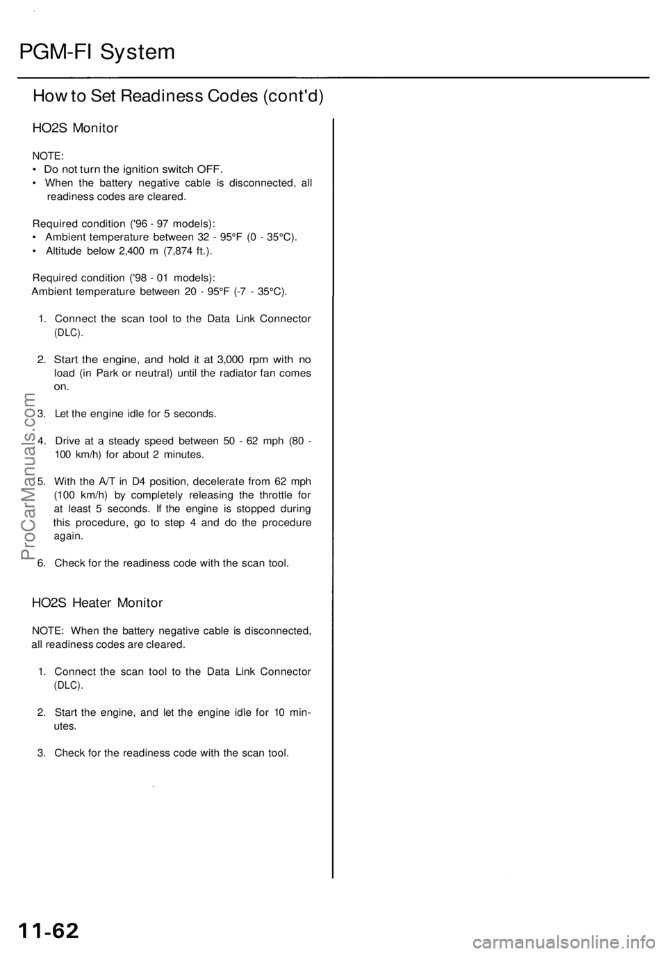
PGM-FI System
How to Set Readiness Codes (cont'd)
HO2S Monitor
NOTE:
• Do not turn the ignition switch OFF.
• When the battery negative cable is disconnected, all
readiness codes are cleared.
Required condition ('96 - 97 models):
• Ambient temperature between 32 - 95°F (0 - 35°C).
• Altitude below 2,400 m (7,874 ft.).
Required condition ('98 - 01 models):
Ambient temperature between 20 - 95°F (-7 - 35°C).
1. Connect the scan tool to the Data Link Connector
(DLC).
2. Start the engine, and hold it at 3,000 rpm with no
load (in Park or neutral) until the radiator fan comes
on.
3. Let the engine idle for 5 seconds.
4. Drive at a steady speed between 50 - 62 mph (80 -
100 km/h) for about 2 minutes.
5. With the A/T in D4 position, decelerate from 62 mph
(100 km/h) by completely releasing the throttle for
at least 5 seconds. If the engine is stopped during
this procedure, go to step 4 and do the procedure
again.
6. Check for the readiness code with the scan tool.
HO2S Heater Monitor
NOTE: When the battery negative cable is disconnected,
all readiness codes are cleared.
1. Connect the scan tool to the Data Link Connector
(DLC).
2. Start the engine, and let the engine idle for 10 min-
utes.
3. Check for the readiness code with the scan tool.ProCarManuals.com
Page 565 of 1954
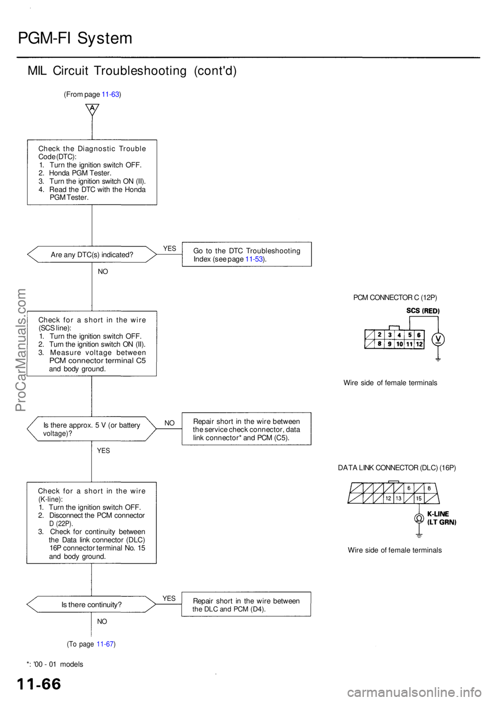
PGM-FI Syste m
MIL Circui t Troubleshootin g (cont'd )
(From pag e 11-63 )
Chec k th e Diagnosti c Troubl e
Cod e (DTC) :
1 . Tur n th e ignitio n switc h OFF .
2 . Hond a PG M Tester .
3 . Tur n th e ignitio n switc h O N (II) .
4 . Rea d th e DT C wit h th e Hond a
PG M Tester .
Ar e an y DTC(s ) indicated ?
NO
Chec k fo r a shor t i n th e wir e
(SC S line) :
1 . Tur n th e ignitio n switc h OFF .
2 . Tur n th e ignitio n switc h O N (II) .
3 . Measur e voltag e betwee n
PCM connecto r termina l C 5an d bod y ground .
I s ther e approx . 5 V (o r batter y
voltage) ?
YES
Go t o th e DT C Troubleshootin g
Inde x (se e pag e 11-53 ).
PCM CONNECTO R C (12P )
Wir e sid e o f femal e terminal s
Repai r shor t i n th e wir e betwee n
th e servic e chec k connector , dat a
lin k connector * an d PC M (C5) .
DATA LIN K CONNECTO R (DLC ) (16P )
Wir e sid e o f femal e terminal s
Is ther e continuity ?Repair shor t i n th e wir e betwee nthe DL C an d PC M (D4) .
*: '0 0 - 0 1 model s
(To pag e 11-67 )
NO
YE S
NO
Chec k fo r a shor t i n th e wir e(K-line) :1. Tur n th e ignitio n switc h OFF .
2 . Disconnec t th e PC M connecto r
D (22P) .3. Chec k fo r continuit y betwee n
th e Dat a lin k connecto r (DLC )
16 P connecto r termina l No . 1 5
an d bod y ground .
YES
ProCarManuals.com
Page 566 of 1954
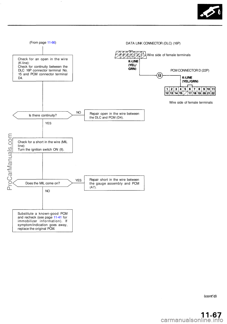
(From pag e 11-66 )
Chec k fo r a n ope n i n th e wir e
(K-line) :Check fo r continuit y betwee n th e
DL C 16 P connecto r termina l No .
1 5 an d PC M connecto r termina l
D4.
DAT A LIN K CONNECTO R (DLC ) (16P )
Wir e sid e o f femal e terminal s
PC M CONNECTO R D (22P )
Wir e sid e o f femal e terminal s
I s ther e continuity ? Repai
r ope n i n th e wir e betwee n
the DL C an d PC M (D4) .
YES
Chec k fo r a shor t i n th e wir e (MI Lline) :Turn th e ignitio n switc h O N (II) .
Doe s th e MI L com e on ?
NO
Repai r shor t i n th e wir e betwee n
th e gaug e assembl y an d PC M
(A7) .
Substitut e a known-goo d PC M
an d rechec k (se e pag e 11-4 1 fo r
immobilize r information) . I f
symptom/indicatio n goe s away ,
replac e th e origina l PCM .
YES
NO
ProCarManuals.com
Page 759 of 1954
Troubleshooting Procedure s
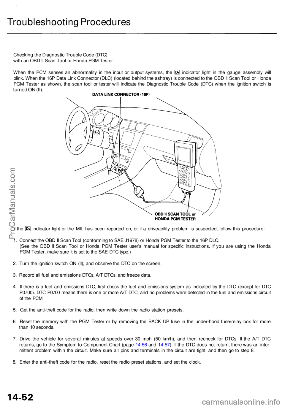
Checking th e Diagnosti c Troubl e Cod e (DTC )
wit h a n OB D II Sca n Too l o r Hond a PG M Teste r
When th e PC M sense s a n abnormalit y i n th e inpu t o r outpu t systems , th e indicato r ligh t i n th e gaug e assembl y wil l
blink . Whe n th e 16 P Dat a Lin k Connecto r (DLC ) (locate d behin d th e ashtray ) i s connecte d to th e OB D II Sca n Too l o r Hond a
PG M Teste r a s shown , th e sca n too l o r teste r wil l indicat e th e Diagnosti c Troubl e Cod e (DTC ) whe n th e ignitio n switc h i s
turne d O N (II) .
If th e indicato r ligh t o r th e MI L ha s bee n reporte d on , o r i f a driveabilit y proble m is suspected , follo w thi s procedure :
1 . Connec t th e OB D II Sca n Too l (conformin g to SA E J1978 ) o r Hond a PG M Teste r t o th e 16 P DLC .
(Se e th e OB D II Sca n Too l o r Hond a PG M Teste r user' s manua l fo r specifi c instructions . I f yo u ar e usin g th e Hond a
PG M Tester , mak e sur e it i s se t t o th e SA E DT C type. )
2 . Tur n th e ignitio n switc h O N (II) , an d observ e th e DT C o n th e screen .
3 . Recor d al l fue l an d emission s DTCs , A/ T DTCs , an d freez e data .
4 . I f ther e is a fue l an d emission s DTC , firs t chec k th e fue l an d emission s syste m a s indicate d b y th e DT C (excep t fo r DT C
P0700) . DT C P070 0 mean s ther e is on e o r mor e A/ T DTC , an d n o problem s wer e detecte d in th e fue l an d emission s circui t
of th e PCM .
5. Ge t th e anti-thef t cod e fo r th e radio , the n writ e dow n th e radi o statio n presets .
6 . Rese t th e memor y wit h th e PG M Teste r o r b y removin g th e BAC K U P fus e i n th e under-hoo d fuse/rela y bo x fo r mor e
tha n 1 0 seconds .
7 . Driv e th e vehicl e fo r severa l minute s a t speed s ove r 3 0 mp h (5 0 km/h) , an d the n rechec k fo r DTCs . I f th e A/ T DT C
returns , g o t o th e Symptom-to-Componen t Char t (pag e 14-5 6 an d 14-57 ). I f th e DT C doe s no t return , ther e wa s a n inter -
mitten t proble m withi n th e circuit . Mak e sur e al l pin s an d terminal s i n th e circui t ar e tight , an d the n g o t o ste p 8 .
8 . Ente r th e anti-thef t cod e fo r th e radio , rese t th e radi o prese t stations , an d se t th e clock .
ProCarManuals.com
Page 1158 of 1954
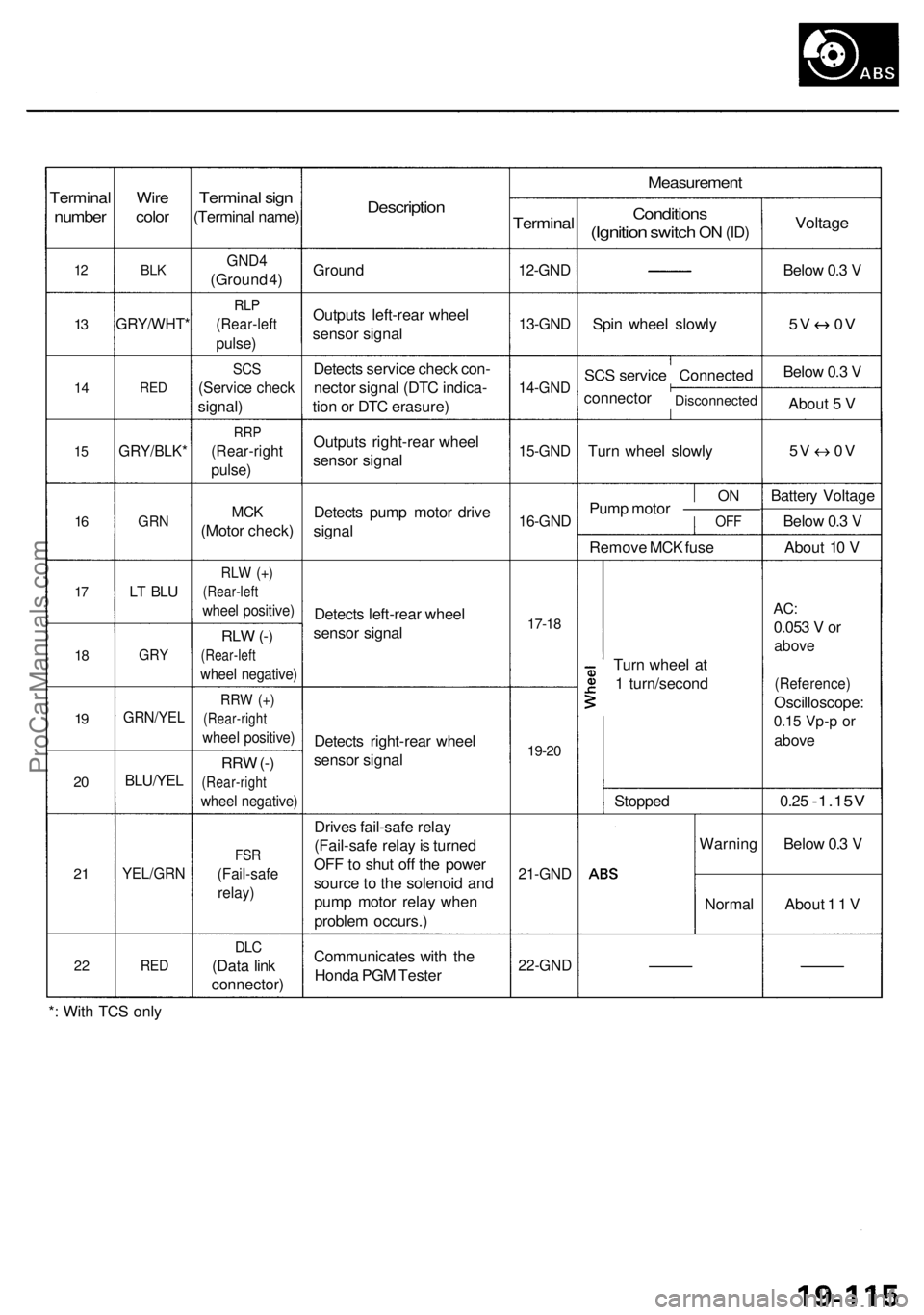
Terminal
number
12
13
1 4
15
16
17
1 8
19
2 0
2 1
2 2
Wir e
colo r
BLK
GRY/WHT *
RED
GRY/BLK *
GRN
LT BL U
GR Y
GRN/YE L
BLU/YEL
YEL/GR N
RED
Termina l sig n
(Termina l name )
GND4
(Groun d 4 )
RL P
(Rear-lef t
pulse)
SCS
(Servic e chec k
signal )
RRP
(Rear-righ t
pulse)
MCK
(Moto r check )
RLW (+ )
(Rear-lef t
wheel positive )
RLW (-)
(Rear-lef t
wheel negative )
RRW (+ )
(Rear-righ t
wheel positive )
RRW (-)
(Rear-righ t
wheel negative )
FSR
(Fail-saf e
relay)
DLC
(Dat a lin k
connector )
Description
Ground
Output s left-rea r whee l
senso r signa l
Detect s servic e chec k con -
necto r signa l (DT C indica -
tio n o r DT C erasure )
Output s right-rea r whee l
senso r signa l
Detect s pum p moto r driv e
signa l
Detect s left-rea r whee l
senso r signa l
Detect s right-rea r whee l
senso r signa l
Drive s fail-saf e rela y
(Fail-saf e rela y is turne d
OF F to shu t of f th e powe r
sourc e to th e solenoi d an d
pum p moto r rela y whe n
proble m occurs. )
Communicate s wit h th e
Hond a PG M Teste r
Measuremen t
Terminal
12-GND
13-GND
14-GN D
15-GND
16-GND
17-18
19-2 0
21-GN D
22-GN D
Condition s
(Ignition switch ON (ID )
Spi n whee l slowl y
SC S servic e Connecte d
connecto r
Disconnecte d
Turn whee l slowl y
ONPum p moto r —————OF F
Remov e MC K fus e
Tur n whee l a t
1 turn/secon d
Stoppe d
Warnin g
Norma l
Voltage
Below 0. 3 V
5 V 0 V
Below 0. 3 V
Abou t 5 V
5V 0 V
Batter y Voltag e
Belo w 0. 3 V
Abou t 1 0 V
AC :
0.05 3 V or
abov e
(Reference )
Oscilloscope :
0.15 Vp- p o r
abov e
0.25 -1.15 V
Below 0. 3 V
Abou t 1 1 V
* : Wit h TC S onl y
ProCarManuals.com