hood release ACURA RL KA9 1996 Service Repair Manual
[x] Cancel search | Manufacturer: ACURA, Model Year: 1996, Model line: RL KA9, Model: ACURA RL KA9 1996Pages: 1954, PDF Size: 61.44 MB
Page 53 of 1954
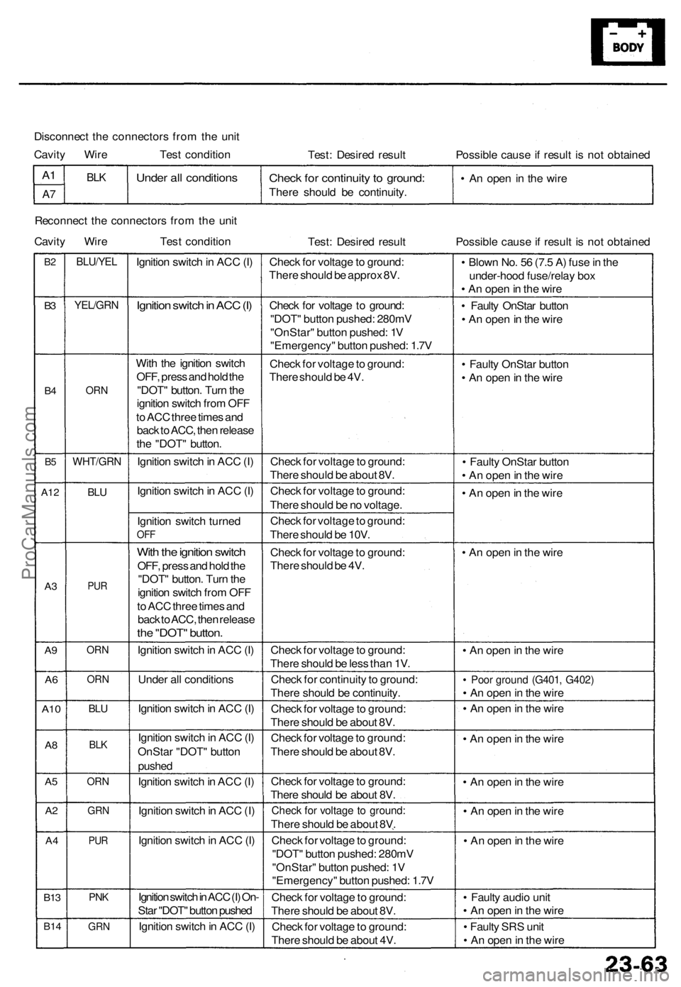
Disconnect the connectors from the unit
Cavity Wire Test condition
Test: Desired result
Possible cause if result is not obtained
A1
A7
BLK
Under all conditions
Check for continuity to ground:
There should be continuity.
• An open in the wire
Reconnect the connectors from the unit
Cavity Wire Test condition
Test: Desired result
Possible cause if result is not obtained
B2
B3
B4
B5
A12
A3
A9
A6
A10
A8
A5
A2
A4
B13
B14
BLU/YEL
YEL/GRN
ORN
WHT/GRN
BLU
PUR
ORN
ORN
BLU
BLK
ORN
GRN
PUR
PNK
GRN
Ignition switch in ACC (I)
Ignition switch in ACC (I)
With the ignition switch
OFF, press and hold the
"DOT" button. Turn the
ignition switch from OFF
to ACC three times and
back to ACC, then release
the "DOT" button.
Ignition switch in ACC (I)
Ignition switch in ACC (I)
Ignition switch turned
OFF
With the ignition switch
OFF, press and hold the
"DOT" button. Turn the
ignition switch from OFF
to ACC three times and
back to ACC, then release
the "DOT" button.
Ignition switch in ACC (I)
Under all conditions
Ignition switch in ACC (I)
Ignition switch in ACC (I)
OnStar "DOT" button
pushed
Ignition switch in ACC (I)
Ignition switch in ACC (I)
Ignition switch in ACC (I)
Ignition switch in ACC (I) On-
Star "DOT" button pushed
Ignition switch in ACC (I)
Check for voltage to ground:
There should be approx 8V.
Check for voltage to ground:
"DOT" button pushed: 280mV
"OnStar" button pushed: 1V
"Emergency" button pushed: 1.7V
Check for voltage to ground:
There should be 4V.
Check for voltage to ground:
There should be about 8V.
Check for voltage to ground:
There should be no voltage.
Check for voltage to ground:
There should be 10V.
Check for voltage to ground:
There should be 4V.
Check for voltage to ground:
There should be less than 1V.
Check for continuity to ground:
There should be continuity.
Check for voltage to ground:
There should be about 8V.
Check for voltage to ground:
There should be about 8V.
Check for voltage to ground:
There should be about 8V.
Check for voltage to ground:
There should be about 8V.
Check for voltage to ground:
"DOT" button pushed: 280mV
"OnStar" button pushed: 1V
"Emergency" button pushed: 1.7V
Check for voltage to ground:
There should be about 8V.
Check for voltage to ground:
There should be about 4V.
• Blown No. 56 (7.5 A) fuse in the
under-hood fuse/relay box
• An open in the wire
• Faulty OnStar button
• An open in the wire
• Faulty OnStar button
• An open in the wire
• Faulty OnStar button
• An open in the wire
• An open in the wire
• An open in the wire
• An open in the wire
• Poor ground (G401, G402)
• An open in the wire
• An open in the wire
• An open in the wire
• An open in the wire
• An open in the wire
• An open in the wire
• Faulty audio unit
• An open in the wire
• Faulty SRS unit
• An open in the wireProCarManuals.com
Page 223 of 1954
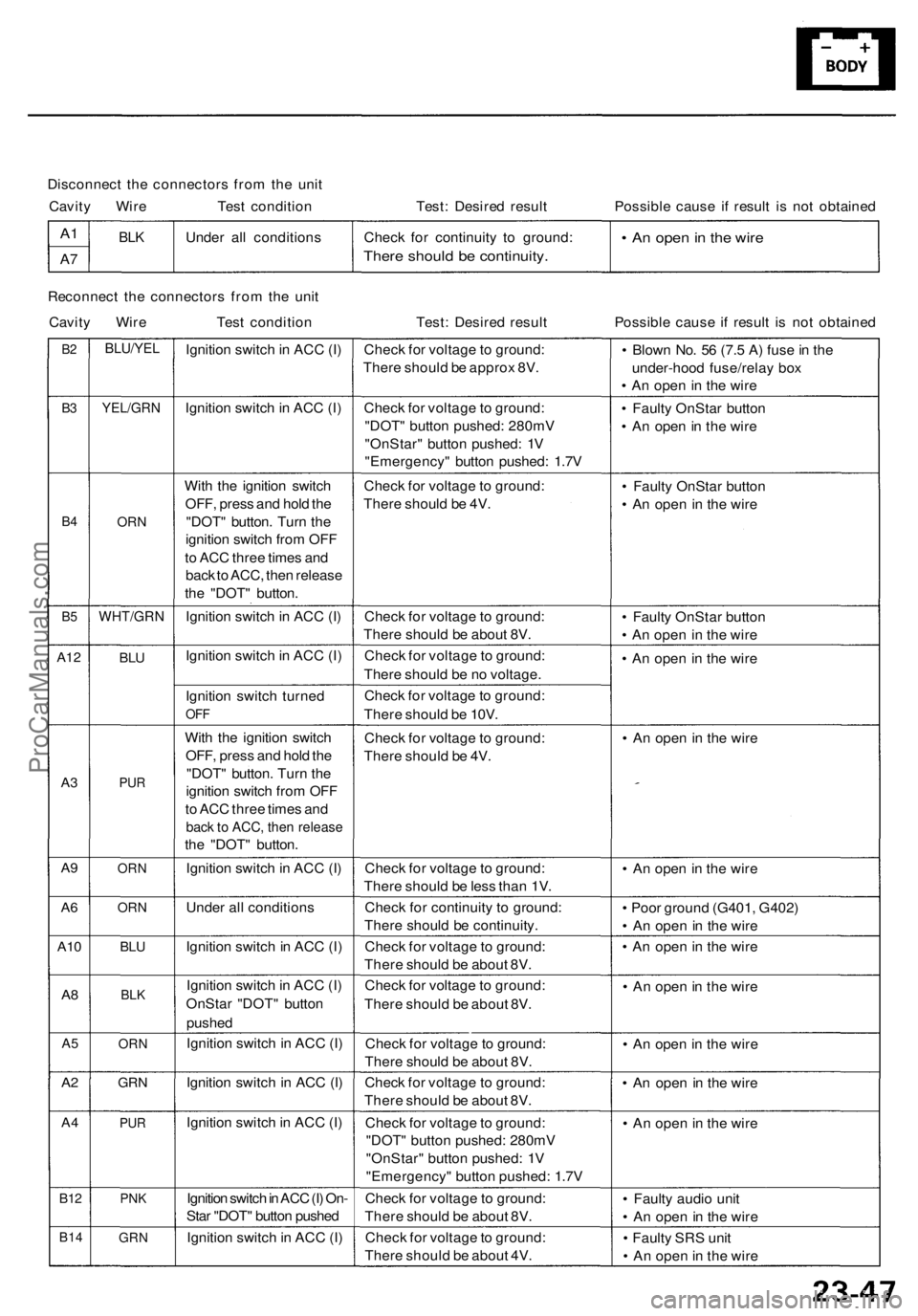
Disconnect the connectors from the unit
Cavity Wire Test condition
Test: Desired result
Possible cause if result is not obtained
A1
A7
BLK
Under all conditions
Check for continuity to ground:
There should be continuity.
• An open in the wire
Reconnect the connectors from the unit
Cavity Wire Test condition
Test: Desired result
Possible cause if result is not obtained
B2
B3
B4
B5
A12
A3
A9
A6
A10
A8
A5
A2
A4
B12
B14
BLU/YEL
YEL/GRN
ORN
WHT/GRN
BLU
PUR
ORN
ORN
BLU
BLK
ORN
GRN
PUR
PNK
GRN
Ignition switch in ACC (I)
Ignition switch in ACC (I)
With the ignition switch
OFF, press and hold the
"DOT" button. Turn the
ignition switch from OFF
to ACC three times and
back to ACC, then release
the "DOT" button.
Ignition switch in ACC (I)
Ignition switch in ACC (I)
Ignition switch turned
OFF
With the ignition switch
OFF, press and hold the
"DOT" button. Turn the
ignition switch from OFF
to ACC three times and
back to ACC, then release
the "DOT" button.
Ignition switch in ACC (I)
Under all conditions
Ignition switch in ACC (I)
Ignition switch in ACC (I)
OnStar "DOT" button
pushed
Ignition switch in ACC (I)
Ignition switch in ACC (I)
Ignition switch in ACC (I)
Ignition switch in ACC (I) On-
Star "DOT" button pushed
Ignition switch in ACC (I)
Check for voltage to ground:
There should be approx 8V.
Check for voltage to ground:
"DOT" button pushed: 280mV
"OnStar" button pushed: 1V
"Emergency" button pushed: 1.7V
Check for voltage to ground:
There should be 4V.
Check for voltage to ground:
There should be about 8V.
Check for voltage to ground:
There should be no voltage.
Check for voltage to ground:
There should be 10V.
Check for voltage to ground:
There should be 4V.
Check for voltage to ground:
There should be less than 1V.
Check for continuity to ground:
There should be continuity.
Check for voltage to ground:
There should be about 8V.
Check for voltage to ground:
There should be about 8V.
Check for voltage to ground:
There should be about 8V.
Check for voltage to ground:
There should be about 8V.
Check for voltage to ground:
"DOT" button pushed: 280mV
"OnStar" button pushed: 1V
"Emergency" button pushed: 1.7V
Check for voltage to ground:
There should be about 8V.
Check for voltage to ground:
There should be about 4V.
• Blown No. 56 (7.5 A) fuse in the
under-hood fuse/relay box
• An open in the wire
• Faulty OnStar button
• An open in the wire
• Faulty OnStar button
• An open in the wire
• Faulty OnStar button
• An open in the wire
• An open in the wire
• An open in the wire
• An open in the wire
• Poor ground (G401, G402)
• An open in the wire
• An open in the wire
• An open in the wire
• An open in the wire
• An open in the wire
• An open in the wire
• Faulty audio unit
• An open in the wire
• Faulty SRS unit
• An open in the wireProCarManuals.com
Page 356 of 1954

Cruise Control
Control Unit Input Test (cont'd)
Cavity Wire
Test condition
Test: Desired result
Possible cause if result is not obtained
3
13
7
6
14
12
2
5
10
9
11
1
BLK
LT GRN
LT GRN/BLK
LT GRN/RED
PNK
BLU/WHT
GRY
GRN/WHT
BLU/YEL
BRN
BRN/BLK
BRN/WHT
Under all conditions
Ignition switch ON (II) and
main switch ON
Resume button pushed
Cancel button pushed
Set button pushed
Cancel button pushed
Shift lever in , or
Ignition switch ON (II), and
main switch ON; raise the
front of the vehicle, and rotate
one wheel slowly while
holding the other wheel.
Ignition switch ON (II), main
switch ON; brake pedal
pressed, then released
Brake pedal pressed then
released
Ignition switch ON (II)
Under all conditions
Under all conditions
Under all conditions
Check for continuity to ground:
There should be continuity.
Check for voltage to ground:
There should be battery voltage.
Check for voltage to ground:
There should be battery voltage.
When testing terminal No. 7, there
should be no voltage on terminal No. 6.
Check for voltage to ground:
There should be battery voltage.
When testing terminal No. 7, there
should be voltage on terminal No. 6.
Check for voltage to ground:
There should be battery voltage.
When testing terminal No. 6, there
should be no voltage on terminal No. 7.
Check for voltage to ground:
There should be battery voltage.
When testing terminal No. 6, there
should be voltage on terminal No. 7.
Check for continuity to ground:
There should be continuity.
NOTE: There should be no continuity
when the shift lever is in other positions.
Check for voltage between the
BLU/ WHT and BLK terminals:
There should be cycle 0 - 5 V or
battery voltage.
Check for voltage to ground:
There should be 0 V with the pedal
pressed, and battery voltage with
the pedal released.
Check for voltage to ground:
There should be battery voltage with
the pedal pressed, and 0 V with the
pedal released.
Attach to ground:
The cruise light in the gauge assembly
should come on.
Check for resistance to ground:
There should be 80 -120
Check for resistance to ground:
There should be 70 -110
Check for resistance to ground:
There should be 40 - 60
• Poor ground (G401, G402)
• An open in the wire
• Blown No. 20 (20 A) fuse in the
under-dash fuse/relay box
• Faulty main switch
• An open in the wire
• Blown No. 39 (15 A) fuse in the
under-hood fuse/relay box
• Faulty horn relay
• Faulty set/resume/cancel switch
• Faulty cable reel
• An open in the wire
• Short between LT GRN/BLK and
LT GRN/RED wires
• Blown No. 39 (15 A) fuse in the
under-hood fuse/relay box
• Faulty horn relay
• Faulty set/resume/cancel switch
• Faulty cable reel
• An open in the wire
• Blown No. 39 (15 A) fuse in the
under-hood fuse/relay box
• Faulty horn relay
• Faulty set/resume/cancel switch
• Faulty cable reel
• An open in the wire
• Short between LT GRN/BLK and
LT GRN/RED wires
• Blown No. 39 (15 A) fuse in the
under-hood fuse/relay box
• Faulty horn relay
• Faulty set/resume/cancel switch
• Faulty cable reel
• An open in the wire
• Faulty A/T gear position switch
• Poor ground (G401, G402)
• An open in the wire
• Faulty vehicle speed sensor (VSS)
• An open in the wire
• Short to ground
• Blown No. 39 (15 A) fuse in the
under-hood fuse/relay box
• Faulty brake switch
• An open in the wire
• Blown No. 39 (15 A) fuse in the
under-hood fuse/relay box
• Faulty brake switch
• An open in the wire
• Blown bulb
• Faulty gauge circuit
• An open in the wire
• Faulty actuator solenoid
• An open in the wireProCarManuals.com
Page 1719 of 1954
Security Alar m Syste m
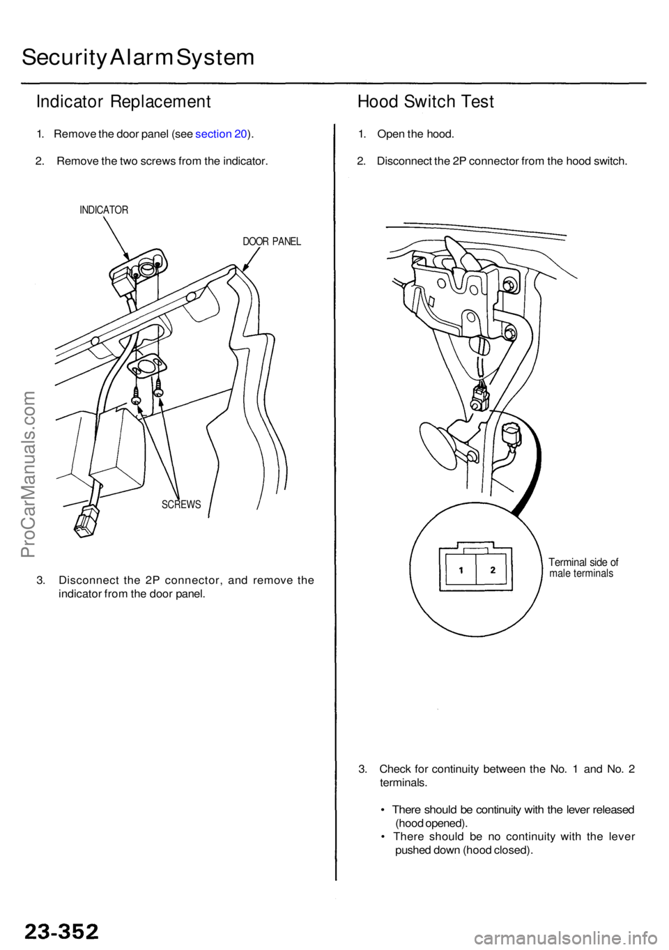
Indicato r Replacemen t
1. Remov e th e doo r pane l (se e sectio n 20 ).
2 . Remov e th e tw o screw s fro m th e indicator .
INDICATO R
DOOR PANE L
3. Disconnec t th e 2 P connector , an d remov e th e
indicato r fro m th e doo r panel .
Hood Switc h Tes t
1. Ope n th e hood .
2 . Disconnec t th e 2 P connecto r fro m th e hoo d switch .
3 . Chec k fo r continuit y betwee n th e No . 1 an d No . 2
terminals .
• Ther e shoul d b e continuit y wit h th e leve r release d
(hood opened) .
• Ther e shoul d b e n o continuit y wit h th e leve r
pushe d dow n (hoo d closed) .
SCREW S
Terminal sid e o fmal e terminal s
ProCarManuals.com