height ACURA RL KA9 1996 Service Repair Manual
[x] Cancel search | Manufacturer: ACURA, Model Year: 1996, Model line: RL KA9, Model: ACURA RL KA9 1996Pages: 1954, PDF Size: 61.44 MB
Page 296 of 1954
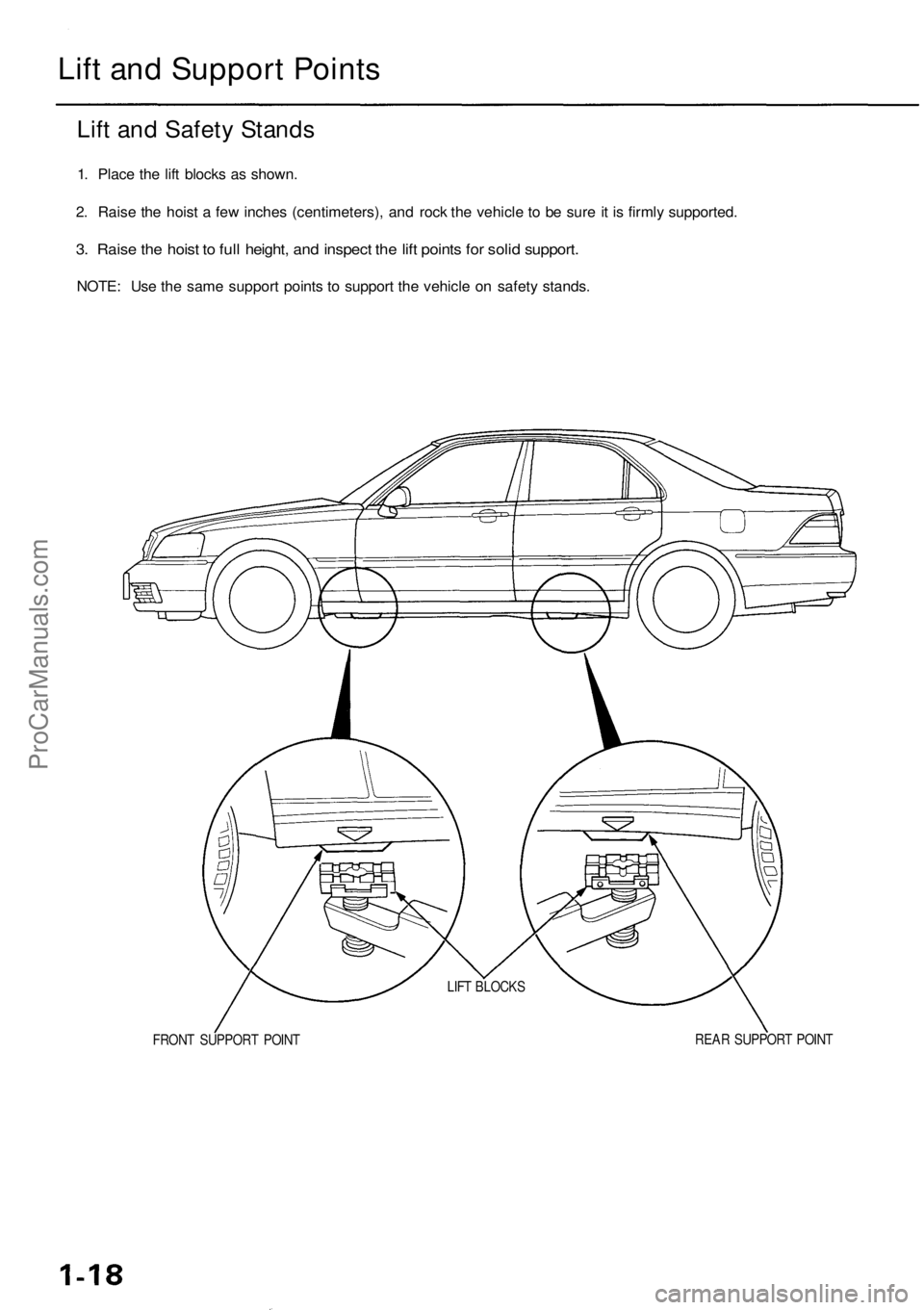
Lift an d Suppor t Point s
Lift an d Safet y Stand s
1. Plac e th e lif t block s a s shown .
2 . Rais e th e hois t a fe w inche s (centimeters) , an d roc k th e vehicl e t o b e sur e it i s firml y supported .
3. Rais e th e hois t t o ful l height , an d inspec t th e lif t point s fo r soli d support .
NOTE: Us e th e sam e suppor t point s t o suppor t th e vehicl e o n safet y stands .
FRONT SUPPOR T POIN T REA
R SUPPOR T POIN T
LIF
T BLOCK S
ProCarManuals.com
Page 370 of 1954
Engine Removal/Installatio n
Removal (cont'd )
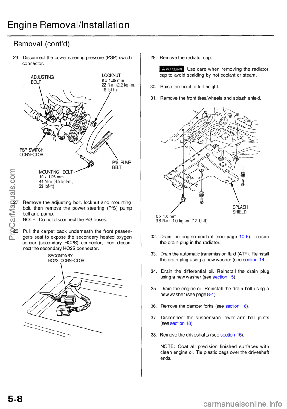
26. Disconnec t th e powe r steerin g pressur e (PSP ) switc h
connector .
ADJUSTIN GBOLT
LOCKNU T8 x 1.2 5 mm22 N- m (2. 2 kgf-m ,
1 6 Ibf-ft )
PS P SWITC H
CONNECTO R
P/S PUM P
BELTMOUNTIN G BOL T10 x 1.2 5 mm44 N- m (4. 5 kgf-m ,
3 3 Ibf-ft )
27. Remov e th e adjustin g bolt , locknu t an d mountin g
bolt, the n remov e th e powe r steerin g (P/S ) pum p
belt an d pump .
NOTE: D o no t disconnec t th e P/ S hoses .
28 . Pul l th e carpe t bac k underneat h th e fron t passen -
ger' s sea t t o expos e th e secondar y heate d oxyge n
senso r (secondar y HO2S ) connector , the n discon -
nec t th e secondar y HO2 S connector . 29
. Remov e th e radiato r cap .
Us e car e whe n removin g th e radiato r
ca p to avoi d scaldin g b y ho t coolan t o r steam .
30 . Rais e th e hois t t o ful l height .
31 . Remov e th e fron t tires/wheel s an d splas h shield .
SPLAS H
SHIEL D
6 x 1. 0 m m9.8 N- m (1. 0 kgf-m , 7. 2 Ibf-ft )
32. Drai n th e engin e coolan t (se e pag e 10-5 ). Loose n
the drai n plu g in th e radiator .
33. Drai n th e automati c transmissio n flui d (ATF) . Reinstal l
th e drai n plu g usin g a ne w washe r (se e sectio n 14 ).
34 . Drai n th e differentia l oil . Reinstal l th e drai n plu g
usin g a ne w washer (see sectio n 15 ).
35 . Drai n th e engin e oil . Reinstal l th e drai n bol t usin g a
ne w washe r (se e pag e 8-4 ).
36 . Remov e th e dampe r fork s (se e sectio n 18 ).
37 . Disconnec t th e suspensio n lowe r ar m bal l joint s
(se e sectio n 18 ).
38 . Remov e th e driveshaft s (se e sectio n 16 ).
NOTE : Coa t al l precisio n finishe d surface s wit h
clea n engin e oil . Ti e plasti c bag s ove r th e driveshaf t
ends.
SECONDAR Y
HO2 S CONNECTO R
ProCarManuals.com
Page 411 of 1954
4. Remove the bolts, then remove the camshaft hold-
ers from the cylinder head.
5. Lift the camshaft out of the cylinder head, wipe it
clean, then inspect the lift ramps. Replace the
camshaft if any lobes are pitted, scored, or excessively
worn.
6. Clean the camshaft bearing surfaces in the cylinder
head, then set the camshaft back in place.
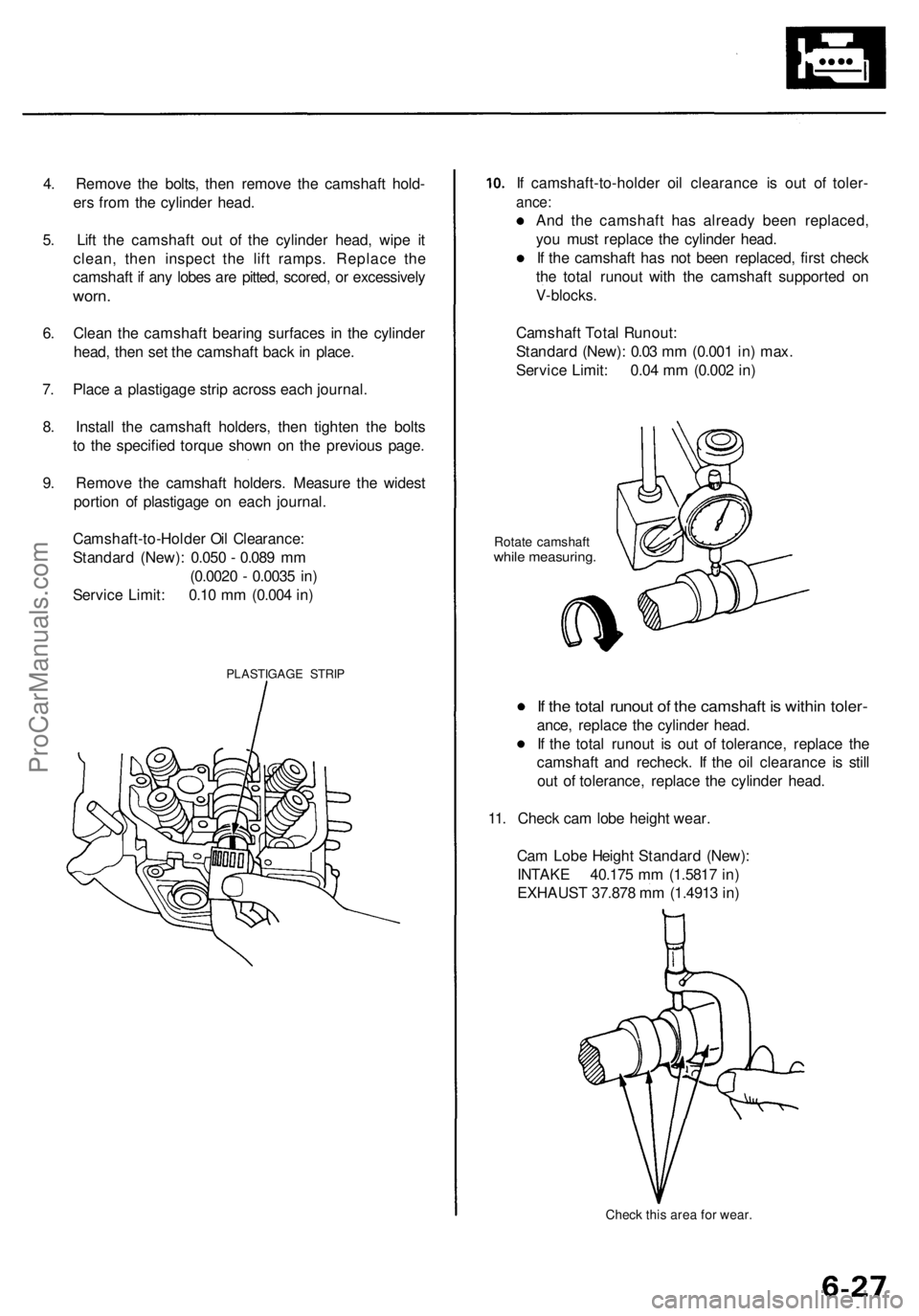
7. Place a plastigage strip across each journal.
8. Install the camshaft holders, then tighten the bolts
to the specified torque shown on the previous page.
9. Remove the camshaft holders. Measure the widest
portion of plastigage on each journal.
PLASTIGAGE STRIP
If camshaft-to-holder oil clearance is out of toler-
ance:
And the camshaft has already been replaced,
you must replace the cylinder head.
If the camshaft has not been replaced, first check
the total runout with the camshaft supported on
V-blocks.
Rotate camshaft
while measuring.
If the total runout of the camshaft is within toler-
ance, replace the cylinder head.
If the total runout is out of tolerance, replace the
camshaft and recheck. If the oil clearance is still
out of tolerance, replace the cylinder head.
11. Check cam lobe height wear.
Check this area for wear.
Cam Lobe Height Standard (New):
INTAKE 40.175 mm (1.5817 in)
EXHAUST 37.878 mm (1.4913 in)
Camshaft Total Runout:
Standard (New): 0.03 mm (0.001 in) max.
Service Limit: 0.04 mm (0.002 in)
Camshaft-to-Holder Oil Clearance:
Standard (New): 0.050 - 0.089 mm
(0.0020 - 0.0035 in)
Service Limit: 0.10 mm (0.004 in)ProCarManuals.com
Page 415 of 1954
Cylinder Head s
Warpag e
NOTE: I f camshaft-to-holde r oi l clearanc e (se e pag e
6-27) i s no t withi n specifications , th e cylinde r hea d can -
not b e resurfaced .
If camshaft-to-holde r oi l clearanc e i s withi n specifica -
tions, chec k th e cylinde r hea d fo r warpage .
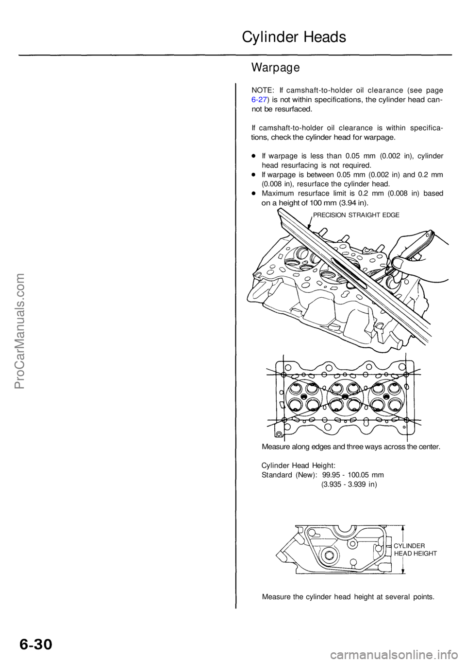
If warpag e i s les s tha n 0.0 5 m m (0.00 2 in) , cylinde r
hea d resurfacin g i s no t required .
I f warpag e i s betwee n 0.0 5 m m (0.00 2 in ) an d 0. 2 m m
(0.00 8 in) , resurfac e th e cylinde r head .
Maximu m resurfac e limi t i s 0. 2 m m (0.00 8 in ) base d
on a heigh t o f 10 0 m m (3.9 4 in) .
Measur e alon g edge s an d thre e way s acros s th e center .
Cylinde r Hea d Height :
Standar d (New) : 99.9 5 - 100.0 5 m m
(3.93 5 - 3.93 9 in )
CYLINDE RHEAD HEIGH T
Measur e th e cylinde r hea d heigh t a t severa l points .
PRECISIO N STRAIGH T EDG E
ProCarManuals.com
Page 417 of 1954
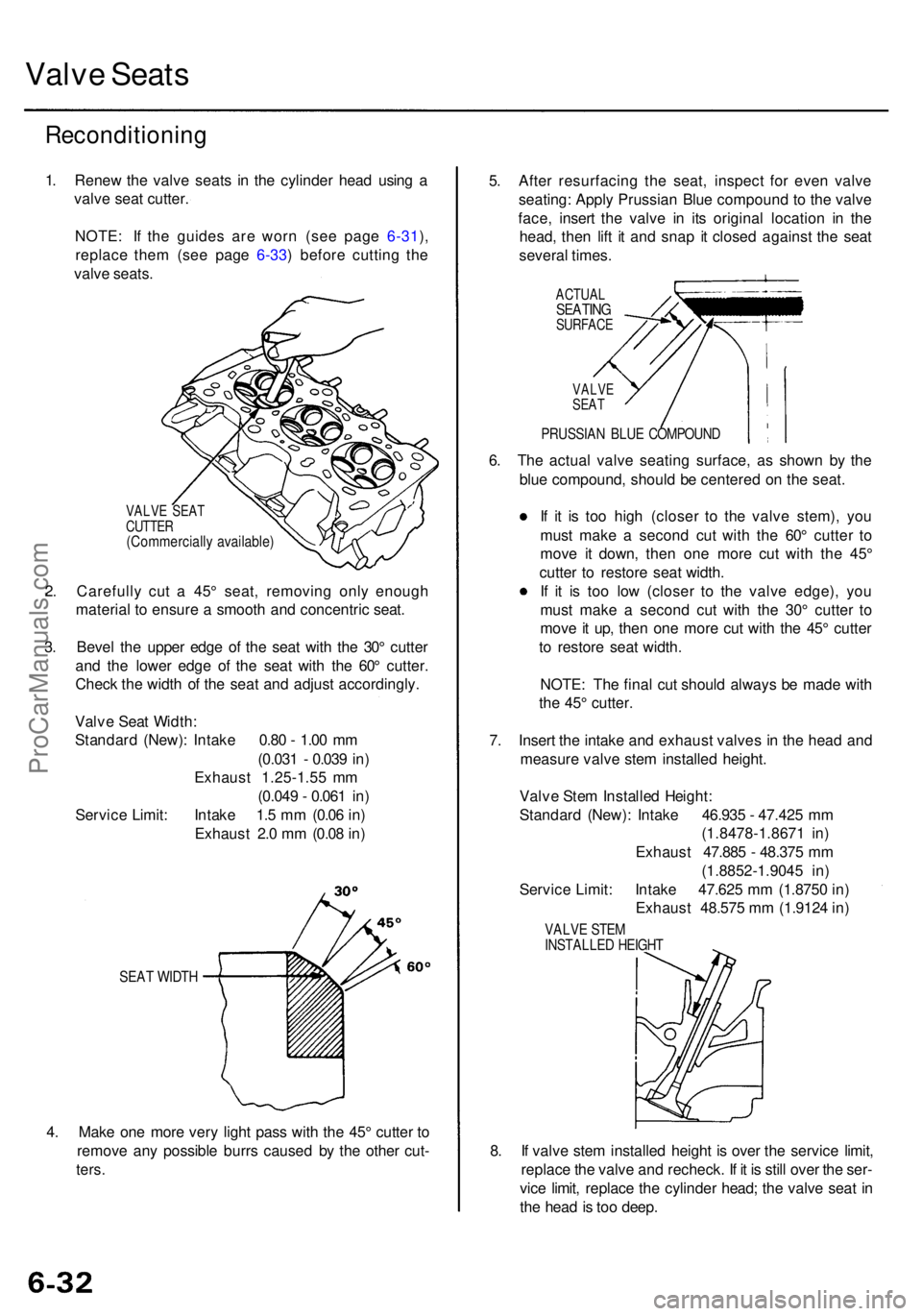
Valve Seat s
Reconditionin g
1. Rene w th e valv e seat s i n th e cylinde r hea d usin g a
valv e sea t cutter .
NOTE : I f th e guide s ar e wor n (se e pag e 6-31 ),
replac e the m (se e pag e 6-33 ) befor e cuttin g th e
valv e seats .
VALV E SEA T
CUTTE R
(Commerciall y available )
2. Carefull y cu t a 45 ° seat , removin g onl y enoug h
materia l t o ensur e a smoot h an d concentri c seat .
3 . Beve l th e uppe r edg e o f th e sea t wit h th e 30 ° cutte r
an d th e lowe r edg e o f th e sea t wit h th e 60 ° cutter .
Chec k th e widt h o f th e sea t an d adjus t accordingly .
SEAT WIDT H
4. Mak e on e mor e ver y ligh t pas s wit h th e 45 ° cutte r t o
remov e an y possibl e burr s cause d b y th e othe r cut -
ters .
5. Afte r resurfacin g th e seat , inspec t fo r eve n valv e
seating : Appl y Prussia n Blu e compoun d t o th e valv e
face , inser t th e valv e i n it s origina l locatio n i n th e
head , the n lif t i t an d sna p i t close d agains t th e sea t
severa l times .
ACTUA LSEATINGSURFAC E
6. Th e actua l valv e seatin g surface , a s show n b y th e
blu e compound , shoul d b e centere d o n th e seat .
I f i t i s to o hig h (close r t o th e valv e stem) , yo u
mus t mak e a secon d cu t wit h th e 60 ° cutte r t o
mov e i t down , the n on e mor e cu t wit h th e 45 °
cutte r t o restor e sea t width .
I f i t i s to o lo w (close r t o th e valv e edge) , yo u
mus t mak e a secon d cu t wit h th e 30 ° cutte r t o
mov e it up , the n on e mor e cu t wit h th e 45 ° cutte r
t o restor e sea t width .
NOTE : Th e fina l cu t shoul d alway s b e mad e wit h
th e 45 ° cutter .
7 . Inser t th e intak e an d exhaus t valve s i n th e hea d an d
measur e valv e ste m installe d height .
8 . I f valv e ste m installe d heigh t i s ove r th e servic e limit ,
replac e th e valv e an d recheck . I f i t i s stil l ove r th e ser -
vic e limit , replac e th e cylinde r head ; th e valv e sea t i n
th e hea d is to o deep .
Valv
e Sea t Width :
Standar d (New) : Intak e 0.8 0 - 1.0 0 m m
(0.03 1 - 0.03 9 in )
Exhaus t 1.25-1.5 5 m m
(0.04 9 - 0.06 1 in )
Servic e Limit : Intak e 1. 5 m m (0.0 6 in )
Exhaus t 2. 0 m m (0.0 8 in ) Valv
e Ste m Installe d Height :
Standar d (New) : Intak e 46.93 5 - 47.42 5 m m
(1.8478-1.867 1 in )
Exhaus t 47.88 5 - 48.37 5 m m
(1.8852-1.904 5 in )
Servic e Limit : Intak e 47.62 5 m m (1.875 0 in )
Exhaus t 48.57 5 m m (1.912 4 in )
VALV E STE MINSTALLE D HEIGH T
VALVESEAT
PRUSSIA N BLU E COMPOUN D
ProCarManuals.com
Page 419 of 1954
Valve Guide s
Replacemen t (cont'd )
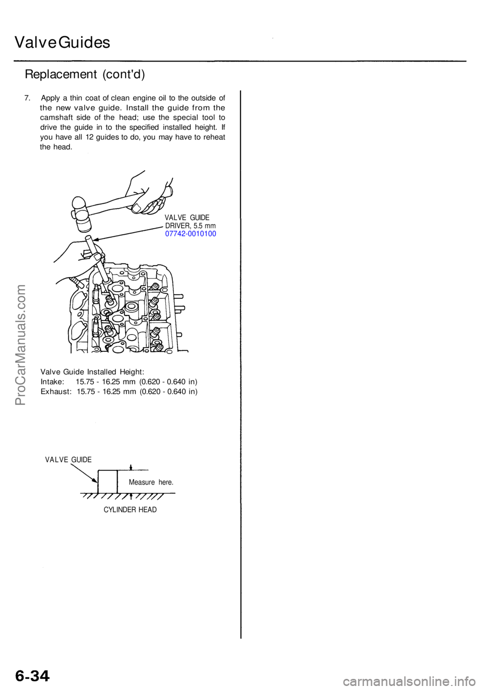
7. Appl y a thi n coa t o f clea n engin e oi l t o th e outsid e o f
the ne w valv e guide . Instal l th e guid e fro m th e
camshaf t sid e o f th e head ; us e th e specia l too l t o
driv e th e guid e i n t o th e specifie d installe d height . I f
yo u hav e al l 1 2 guide s t o do , yo u ma y hav e t o rehea t
th e head .
VALV E GUID E
DRIVER , 5. 5 m m
07742-001010 0
Valve Guid e Installe d Height :
Intake : 15.7 5 - 16.2 5 m m (0.62 0 - 0.64 0 in )
Exhaust : 15.7 5 - 16.2 5 m m (0.62 0 - 0.64 0 in )
VALV E GUID E
Measure here .
CYLINDE R HEA D
ProCarManuals.com
Page 470 of 1954
Oil Pa n
Remova l
Engine remova l i s no t require d i n thi s procedure .
• Mak e sur e jack s an d safet y stand s ar e place d properl y
(se e sectio n 1 ).
• Appl y th e parkin g brak e an d bloc k th e rea r wheel s s o
th e vehicl e wil l no t rol l of f stand s whil e yo u ar e
workin g unde r it .
CAUTION :
• Us e fende r cover s t o avoi d damagin g painte d sur -
faces .
• Unplu g th e wirin g connector s carefull y whil e holdin g
th e connecto r portio n to avoi d damaging .
• Mar k al l wirin g an d hose s t o avoi d misconnection .
Also , b e sur e tha t the y d o no t contac t othe r wirin g
o r hose s o r interfer e wit h othe r parts .
1 . Loose n th e idle r pulle y cente r nu t an d adjustin g bolt ,
the n remov e th e ai r conditionin g (A/C ) compresso r
bel t (se e pag e 5-7 ).
2 . Disconnec t th e powe r steerin g pressur e (PSP )
switc h connector , the n remov e th e powe r steerin g
pum p bel t an d pum p (se e pag e 5-8 ).
3 . Remov e th e lef t an d righ t sid e exhaus t manifol d
covers (se e pag e 9-4 ).
4 . Rais e th e hois t t o ful l height .
5 . Remov e th e fron t tires/wheel s an d splas h shiel d
(se e pag e 5-8 ).
6 . Remov e th e dampe r fork s (se e sectio n 18 ).
7 . Disconnec t th e suspensio n lowe r ar m bal l joint s
with the specia l tool . Refe r t o sectio n 1 8 fo r th e
prope r procedure .
8 . Remov e th e driveshaft s an d intermediat e shaf t (se e
sectio n 16 ).
9 . Drai n th e differentia l oil . Reinstal l th e drai n plu g usin g
a ne w washe r (se e sectio n 15 ).
10 . Drai n th e engin e oil . Reinstal l th e drai n bol t usin g a
ne w washe r (se e pag e 8-4 ).
11 . Disconnec t th e vehicl e spee d senso r (VSS ) connec -
tor , the n remov e th e VSS/powe r steerin g spee d
senso r (se e pag e 5-9 ).
D o no t disconnec t th e flui d hoses .
12 x 1.2 5 mm64 N- m (6. 5 kgf-m , 4 7 Ibf-ft )Apply liqui d gaske t t o th ebol t threads .
12 x 1.2 5 mm64 N- m (6. 5 kgf-m ,
4 7 Ibf-ft )
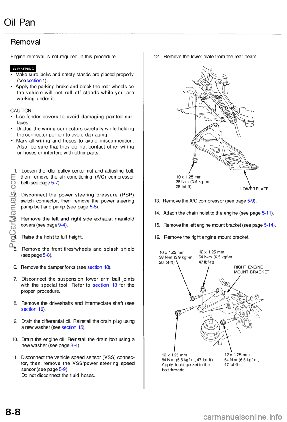
12. Remov e th e lowe r plat e fro m th e rea r beam .
LOWE R PLAT E
10 x 1.2 5 mm38 N- m (3. 9 kgf-m ,
2 8 Ibf-ft )
13. Remov e th e A/ C compresso r (se e pag e 5-9 ).
14 . Attac h th e chai n hois t t o th e engin e (se e pag e 5-11 ).
15 . Remov e th e lef t engin e moun t bracke t (se e pag e 5-14 ).
16 . Remov e th e righ t engin e moun t bracket .
10 x 1.2 5 mm38 N- m (3. 9 kgf-m ,
2 8 Ibf-ft )12 x 1.2 5 mm64 N- m (6. 5 kgf-m ,
4 7 Ibf-ft )
RIGHT ENGIN E
MOUN T BRACKE T
ProCarManuals.com
Page 494 of 1954
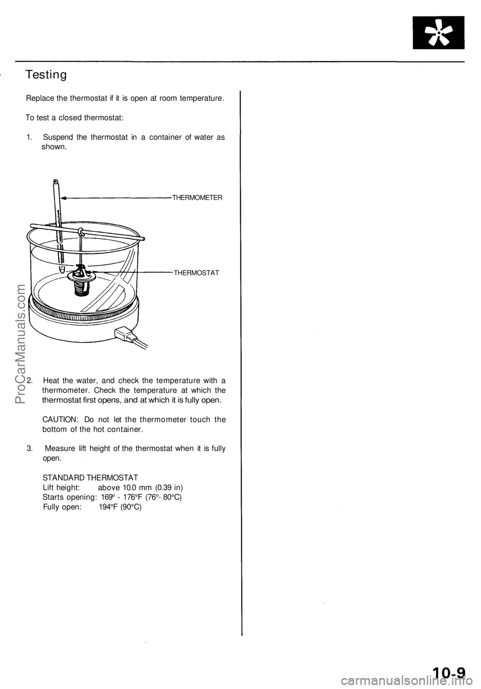
Testing
Replac e th e thermosta t i f i t i s ope n a t roo m temperature .
T o tes t a close d thermostat :
1 . Suspen d th e thermosta t i n a containe r o f wate r a s
shown .
THERMOMETE R
THERMOSTA T
2. Hea t th e water , an d chec k th e temperatur e wit h a
thermometer . Chec k th e temperatur e a t whic h th e
thermosta t firs t opens , an d a t whic h it i s full y open .
CAUTION : D o no t le t th e thermomete r touc h th e
botto m o f th e ho t container .
3 . Measur e lif t heigh t o f th e thermosta t whe n i t i s full y
open .
STANDAR D THERMOSTA T
Lif t height : abov e 10. 0 m m (0.3 9 in )
Start s opening : 169 ° - 176° F (76° - 80°C )
Full y open : 194° F (90°C )
ProCarManuals.com
Page 1019 of 1954
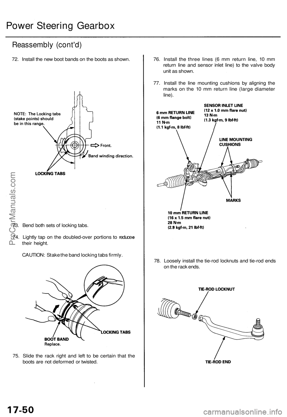
75. Slid e th e rac k righ t an d lef t t o b e certai n tha t th e
boot s ar e no t deforme d o r twisted . 78
. Loosel y instal l th e tie-ro d locknut s an d tie-ro d end s
o n th e rac k ends .
73
. Ben d bot h set s o f lockin g tabs .
74 . Lightl y ta p o n th e doubled-ove r portion s t o reduc e
thei r height .
CAUTION : Stak e th e ban d lockin g tab s firmly . 76
. Instal l th e thre e line s ( 6 m m retur n line , 1 0 m m
retur n lin e an d senso r inle t line ) t o th e valv e bod y
uni t a s shown .
77 . Instal l th e lin e mountin g cushion s b y alignin g th e
mark s o n th e 1 0 m m retur n lin e (larg e diamete r
line).
Reassembl y (cont'd )
72. Instal l th e ne w boo t band s o n th e boot s a s shown .
Power Steerin g Gearbo x
ProCarManuals.com
Page 1051 of 1954
Inspection and Adjustment
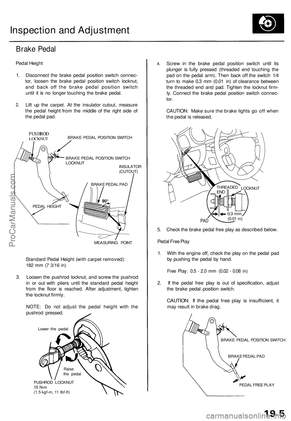
Brake Pedal
Pedal Height
1. Disconnect the brake pedal position switch connec-
tor, loosen the brake pedal position switch locknut,
and back off the brake pedal position switch
until it is no longer touching the brake pedal.
2.
Lift up the carpet. At the insulator cutout, measure
the pedal height from the middle of the right side of
the pedal pad.
PUSHROD
LOCKNUT
BRAKE PEDAL POSITION SWITCH
BRAKE PEDAL POSITION SWITCH
LOCKNUT
INSULATOR
(CUTOUT)
MEASURING POINT
Standard Pedal Height (with carpet removed):
182 mm (7
3/16
in)
3. Loosen the pushrod locknut, and screw the pushrod
in or out with pliers until the standard pedal height
from the floor is reached. After adjustment, tighten
the locknut firmly.
NOTE: Do not adjust the pedal height with the
pushrod pressed.
Lower the pedal
PUSHROD LOCKNUT
15 N-m
(1.5 kgf-m, 11 Ibf-ft)
4.
Screw in the brake pedal position switch until its
plunger is fully pressed (threaded end touching the
pad on the pedal arm). Then back off the switch 1/4
turn to make 0.3 mm (0.01 in) of clearance between
the threaded end and pad. Tighten the locknut firm-
ly. Connect the brake pedal position switch connec-
tor.
CAUTION: Make sure the brake lights go off when
the pedal is released.
PAD
5. Check the brake pedal free play as described below.
Pedal Free Play
1. With the engine off, check the play on the pedal pad
by pushing the pedal by hand.
Free Play: 0.5 - 2.0 mm (0.02 - 0.08 in)
2. If the pedal free play is out of specification, adjust
the brake pedal position switch.
CAUTION: If the pedal free play is insufficient, it
may result in brake drag.
BRAKE PEDAL POSITION SWITCH
BRAKE PEDAL PAD
PEDAL FREE PLAY
LOCKNUT
THREADED
END
0.3 mm
(0.01
in)
BRAKE PEDAL PAD
PEDAL HEIGHT
Raise
the pedalProCarManuals.com