roof ACURA RL KA9 1996 Service Repair Manual
[x] Cancel search | Manufacturer: ACURA, Model Year: 1996, Model line: RL KA9, Model: ACURA RL KA9 1996Pages: 1954, PDF Size: 61.44 MB
Page 17 of 1954
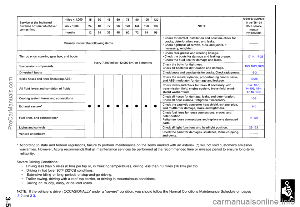
17-14, 17-2 3
18-3, 18-21 , 18-22
16- 3
19-2 8
8-4, 10-5 ,14-108 , 15-4 ,17-16 , 19- 8
10-2
9-5
11-126
23-12 3
* Accordin g t o stat e an d federa l regulations , failur e t o perfor m maintenanc e o n th e item s marke d wit h a n asteris k (* ) wil l no t voi d customer' s emissio n
warranties . However , Acur a recommend s tha t al l maintenanc e services be performe d a t th e recommende d tim e o r mileag e perio d to ensur e long-ter m
reliability .
Severe Drivin g Conditions :
• Drivin g les s tha n 5 mile s ( 8 km ) pe r tri p or , i n freezin g temperatures , drivin g les s tha n 1 0 mile s (1 6 km ) pe r trip .
• Drivin g in ho t [ove r 90° F (32°C) ] conditions .
• Extensiv e idlin g o r lon g period s o f stop-and-g o driving .
• Traile r towing , drivin g wit h a roof-to p carrier , o r drivin g in mountainou s conditions .
• Drivin g o n muddy , dusty , o r de-ice d roads .
NOTE: I f th e vehicl e is drive n OCCASIONALL Y unde r a "severe " condition , yo u shoul d follo w th e Norma l Condition s Maintenanc e Schedul e o n page s
3-2 and 3-3 .
ProCarManuals.com
Page 206 of 1954
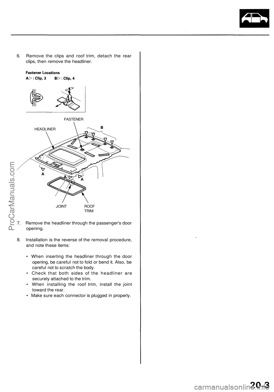
6. Remove the clips and roof trim, detach the rear
clips, then remove the headliner.
FASTENER
HEADLINER
JOINT
ROOF
TRIM
7. Remove the headliner through the passenger's door
opening.
8. Installation is the reverse of the removal procedure,
and note these items:
• When inserting the headliner through the door
opening, be careful not to fold or bend it. Also, be
careful not to scratch the body.
• Check that both sides of the headliner are
securely attached to the trim.
• When installing the roof trim, install the joint
toward the rear.
• Make sure each connector is plugged in properly.ProCarManuals.com
Page 260 of 1954
Voice contro l doe s no t wor k
Diagnosti c Test : Navigatio n Syste m Lin k an d
Functiona l Setu p
NOTE :
• Alway s chec k th e connector s fo r poo r connection s o r
loos e terminals .
• Befor e troubleshooting , writ e dow n th e customer' s
radi o statio n presets , an d ge t th e radi o an d naviga -
tio n syste m anti-thef t codes .
• Afte r troubleshooting , ente r th e radi o an d navigatio n
syste m anti-thef t codes , an d th e radi o statio n presets .
Befor e assumin g tha t a voic e contro l complain t i s
hardwar e related , ensur e tha t th e voic e contro l syste m
i s bein g operate d correctly .
• Mak e sur e yo u ar e o n th e correc t scree n whe n tryin g
t o issu e a voic e command . Fo r instance , th e com -
man d "Fin d th e neares t Italia n Restaurant " onl y
work s o n a Ma p screen . (Se e th e Navigatio n Owner' s
manua l fo r a complet e lis t o f allowe d voic e com -
mand s fo r th e informatio n bein g displayed) .
• Clos e th e window s an d sunroof .
• Se t th e fa n spee d t o lo w (1 o r 2) .
• Adjus t th e ai r flo w fro m th e dashboar d vent s s o tha t
they d o no t blo w agains t th e microphon e o n th e
celling .
• Paus e afte r pressin g th e TAL K button , the n giv e a
voic e comman d in a clear , natura l speakin g voice .
I f th e syste m canno t recogniz e you r command , spea k
louder .
• I f th e microphon e pick s u p voice s othe r tha n yours ,
th e syste m ma y no t interpre t you r voic e command s
correctly .
• I f yo u spea k a comman d wit h somethin g in you r
mouth , o r you r voic e is eithe r to o hig h o r to o husky ,
th e syste m ma y misinterpre t you r command .
1 . G o int o th e Diagnosti c mod e an d us e th e "Mi c Level "
diagnosti c th e unde r Functiona l Setu p (se e pag e 23 -48
t o chec k th e operatio n o f th e TAL K an d BAC K but -
tons.
Are the TALK and BACK buttons operational?
YES—G o to ste p 2 .
NO—Chec k fo r a n ope n o r shor t t o groun d o n naviga -
tio n uni t connecto r B (14P ) termina l No . 10 . 2
. Us e th e "Mi c Level " diagnosti c unde r Functiona l
Setu p (se e pag e 23-48 ) t o chec k th e operatio n o f th e
microphone .
Is the microphone operational?
YES—Chec k th e operatio n o f th e voic e contro l sys -
te m (Se e th e Navigatio n Syste m Owner' s Manual) .
NO—Chec k fo r a loos e o r missin g microphon e assembly .
I f OK , chec k fo r a n ope n o r shor t t o groun d o n navigatio n
uni t connecto r B (14P ) terminal s No . 6 an d No . 14 .
Curso r constantl y leave s roa d
Diagnosti c Test : Ya w Rat e an d Ca r Statu s
1 . Chec k th e GP S ico n o n th e navigatio n picture .
Is the GPS icon white?
YES—D o th e troubleshootin g fo r GP S ico n i s whit e
(see page 23-32)
NO—G o t o ste p 2 .
2 . G o int o th e Diagnosti c mod e an d us e th e "Ya w Rate "
diagnosti c (se e pag e 23-47 ) t o chec k th e ya w rat e
sensor .
3. G o int o th e Diagnosti c mod e an d us e th e "Ca r
Status " diagnosti c (se e pag e 23-45 ) t o chec k th e vehi -
cl e spee d pulse .
Are the yaw rate sensor and vehicle speed pulse OK?
YES—Th e proble m ma y b e normal . Chec k t o se e if
th e proble m occur s i n th e sam e place . I f i t does , th e
proble m coul d b e in th e database . G o to ste p 4 .
NO—I f th e proble m is th e ya w rat e sensor , replac e
the navigatio n uni t (se e pag e 23-53 ). I f th e proble m is
th e vehicl e spee d pulse , troubleshoo t th e vehicl e
spee d signa l circuit .
4 . Substitut e a known-goo d navigatio n uni t an d chec k
t o se e if th e proble m occur s i n th e sam e place .
Doe s the problem occur in the same place?
YES—Th e proble m is in th e database . Repor t th e
proble m accordin g t o th e Navigatio n Syste m
Owner' s Manua l unde r "Reportin g Errors" .
NO—Replac e th e navigatio n uni t
(se e pag e 53 ).
ProCarManuals.com
Page 314 of 1954
According t o stat e an d federa l regulations , failur e t o perfor m maintenanc e o n th e item s marke d wit h a n asteris k (* ) wil l no t voi d customer' s emissio n
warranties . However , Acur a recommend s tha t al l maintenanc e service s b e performe d a t th e recommende d tim e o r mileag e perio d to ensur e long-ter m
reliability .
Severe Drivin g Conditions :
• Drivin g les s tha n 5 mile s ( 8 km ) pe r tri p or , i n freezin g temperatures , drivin g les s tha n 1 0 mile s (1 6 km ) pe r trip .
• Drivin g in ho t [ove r 90° F (32°C) ] conditions .
• Extensiv e idlin g o r lon g period s o f stop-and-g o driving .
• Traile r towing , drivin g wit h a roof-to p carrier , o r drivin g i n mountainou s conditions .
• Drivin g o n muddy , dusty , o r de-ice d roads .
NOTE : I f th e vehicl e is drive n OCCASIONALL Y unde r a
3-4 and 3-5 .
'severe " condition , yo u shoul d follo w th e Norma l Condition s Maintenanc e Schedul e o n page s
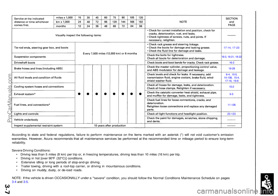
23-12 3
11-126
9-5
10-2
8-4
, 10-5 ,
14-108 , 15-4 ,
17-16 , 19- 8
19-2 8
16-3
18-3 , 18-21 , 18-2 2
17-14, 17-2 3
ProCarManuals.com
Page 318 of 1954
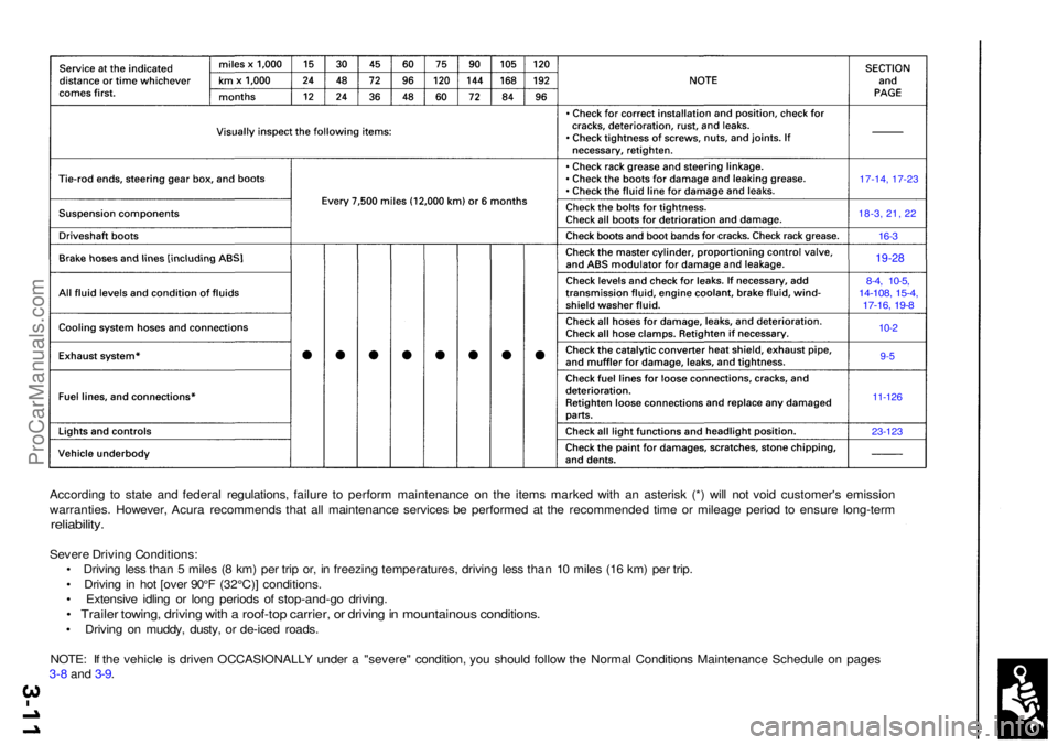
According t o stat e an d federa l regulations , failur e t o perfor m maintenanc e o n th e item s marke d wit h a n asteris k (* ) wil l no t voi d customer' s emissio n
warranties . However , Acur a recommend s tha t al l maintenanc e service s b e performe d a t th e recommende d tim e o r mileag e perio d t o ensur e long-ter m
reliability.
Severe Drivin g Conditions :
• Drivin g les s tha n 5 mile s ( 8 km ) pe r tri p or , i n freezin g temperatures , drivin g les s tha n 1 0 mile s (1 6 km ) pe r trip .
• Drivin g in ho t [ove r 90° F (32°C) ] conditions .
• Extensiv e idlin g o r lon g period s o f stop-and-g o driving .
• Traile r towing , drivin g wit h a roof-to p carrier , o r drivin g in mountainou s conditions .
• Drivin g o n muddy , dusty , o r de-ice d roads .
NOTE : I f th e vehicl e is drive n OCCASIONALL Y unde r a "severe " condition , yo u shoul d follo w th e Norma l Condition s Maintenanc e Schedul e o n page s
3-8 and 3-9 .
17-14, 17-2 3
18-3, 21, 2 2
16-3
19-28
8-4 , 10-5 ,14-108 , 15-4 ,17-16 , 19- 8
10-2
9-5
11-126
23-12 3
ProCarManuals.com
Page 322 of 1954
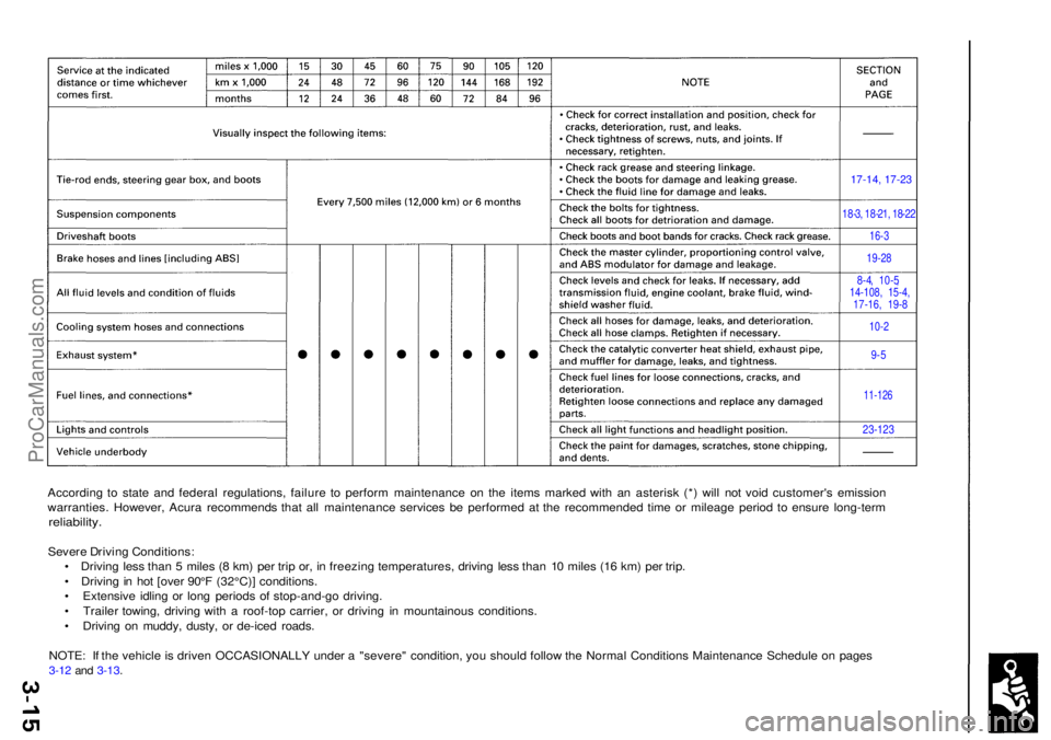
According t o stat e an d federa l regulations , failur e t o perfor m maintenanc e o n th e item s marke d wit h a n asteris k (* ) wil l no t voi d customer' s emissio n
warranties . However , Acur a recommend s tha t al l maintenanc e service s b e performe d a t th e recommende d tim e o r mileag e perio d t o ensur e long-ter m
reliability.
Severe Drivin g Conditions :
• Drivin g les s tha n 5 mile s ( 8 km ) pe r tri p or , i n freezin g temperatures , drivin g les s tha n 1 0 mile s (1 6 km ) pe r trip .
• Drivin g in ho t [ove r 90° F (32°C) ] conditions .
• Extensiv e idlin g o r lon g period s o f stop-and-g o driving .
• Traile r towing , drivin g wit h a roof-to p carrier , o r drivin g i n mountainou s conditions .
• Drivin g o n muddy , dusty , o r de-ice d roads .
NOTE : I f th e vehicl e is drive n OCCASIONALL Y unde r a "severe " condition , yo u shoul d follo w th e Norma l Condition s Maintenanc e Schedul e o n page s
3-1 2 an d 3-13 .
17-14, 17-23
18-3, 18-21, 18-22
16-3
19-28
8-4, 10-5,14-108, 15-4,17-16, 19-8
10-2
9-5
11-126
23-123
ProCarManuals.com
Page 629 of 1954
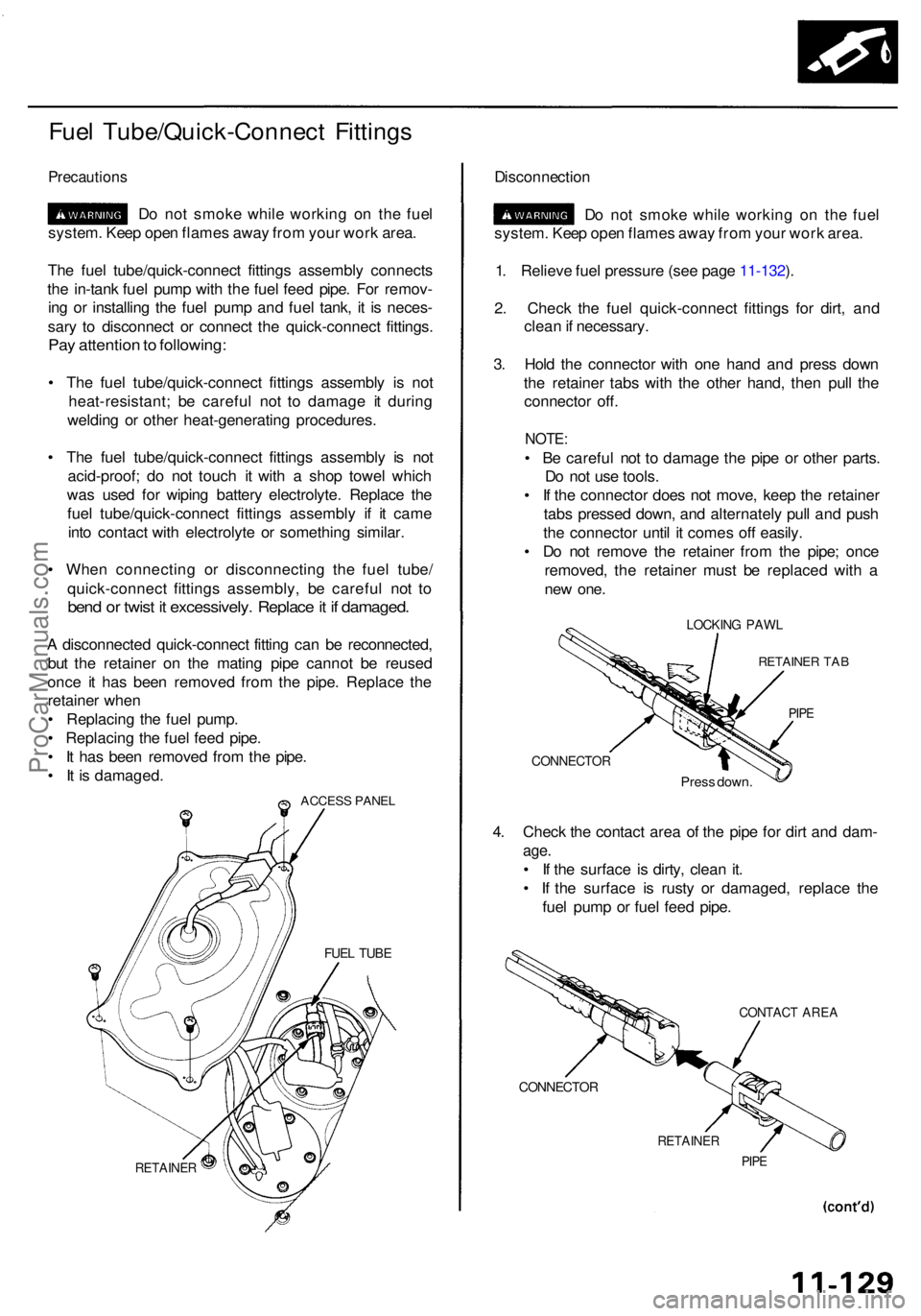
Fuel Tube/Quick-Connec t Fitting s
Precaution s
Do no t smok e whil e workin g o n th e fue l
system . Kee p ope n flame s awa y fro m you r wor k area .
Th e fue l tube/quick-connec t fitting s assembl y connect s
th e in-tan k fue l pum p wit h th e fue l fee d pipe . Fo r remov -
in g o r installin g th e fue l pum p an d fue l tank , i t i s neces -
sar y t o disconnec t o r connec t th e quick-connec t fittings .
Pay attentio n to following :
• Th e fue l tube/quick-connec t fitting s assembl y i s no t
heat-resistant ; b e carefu l no t t o damag e i t durin g
weldin g o r othe r heat-generatin g procedures .
• Th e fue l tube/quick-connec t fitting s assembl y i s no t
acid-proof ; d o no t touc h i t wit h a sho p towe l whic h
wa s use d fo r wipin g batter y electrolyte . Replac e th e
fue l tube/quick-connec t fitting s assembl y i f i t cam e
int o contac t wit h electrolyt e o r somethin g similar .
• Whe n connectin g o r disconnectin g th e fue l tube /
quick-connec t fitting s assembly , b e carefu l no t t o
ben d o r twis t i t excessively . Replac e it i f damaged .
A disconnecte d quick-connec t fittin g ca n b e reconnected ,
bu t th e retaine r o n th e matin g pip e canno t b e reuse d
onc e i t ha s bee n remove d fro m th e pipe . Replac e th e
retaine r whe n
• Replacin g th e fue l pump .
• Replacin g th e fue l fee d pipe .
• I t ha s bee n remove d fro m th e pipe .
• I t i s damaged .
ACCESS PANE L
RETAINE R
Disconnectio n
D o no t smok e whil e workin g o n th e fue l
system . Kee p ope n flame s awa y fro m you r wor k area .
1 . Reliev e fue l pressur e (se e pag e 11-132 ).
2 . Chec k th e fue l quick-connec t fitting s fo r dirt , an d
clea n if necessary .
3 . Hol d th e connecto r wit h on e han d an d pres s dow n
th e retaine r tab s wit h th e othe r hand , the n pul l th e
connecto r off .
NOTE :
• B e carefu l no t t o damag e th e pip e o r othe r parts .
D o no t us e tools .
• I f th e connecto r doe s no t move , kee p th e retaine r
tab s presse d down , an d alternatel y pul l an d pus h
th e connecto r unti l i t come s of f easily .
• D o no t remov e th e retaine r fro m th e pipe ; onc e
removed , th e retaine r mus t b e replace d wit h a
ne w one .
LOCKIN G PAW L
RETAINE R TA B
PIPE
CONNECTO R
Press down .
4. Chec k th e contac t are a o f th e pip e fo r dir t an d dam -
age.
• I f th e surfac e i s dirty , clea n it .
• I f th e surfac e i s rust y o r damaged , replac e th e
fue l pum p o r fue l fee d pipe .
CONTAC T ARE A
CONNECTO R
RETAINER
PIPE
FUE L TUB E
ProCarManuals.com
Page 1327 of 1954
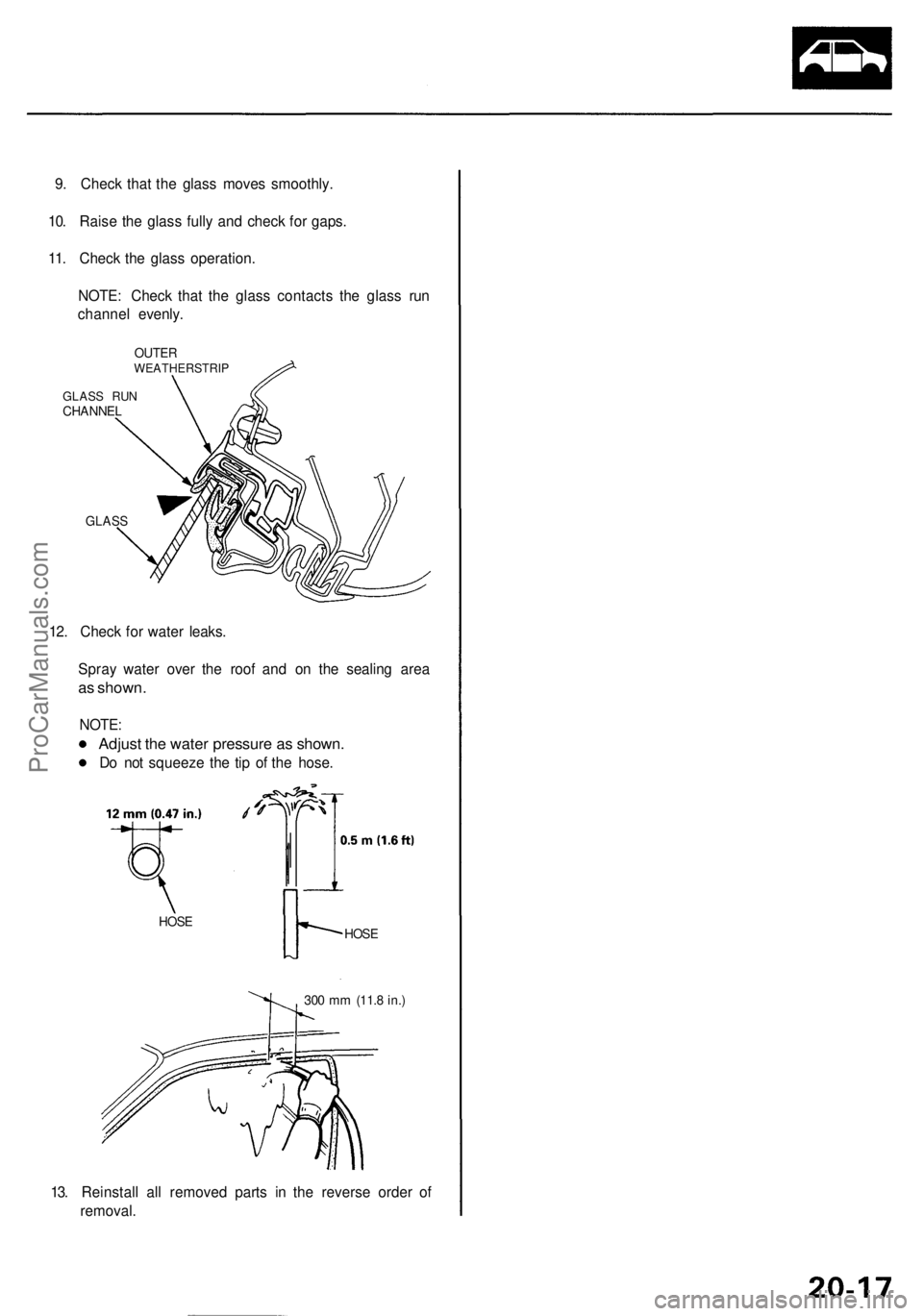
9. Check that the glass moves smoothly.
10. Raise the glass fully and check for gaps.
11. Check the glass operation.
NOTE: Check that the glass contacts the glass run
channel evenly.
OUTER
WEATHERSTRIP
GLASS RUN
CHANNEL
GLASS
12. Check for water leaks.
Spray water over the roof and on the sealing area
as shown.
NOTE:
Adjust the water pressure as shown.
Do not squeeze the tip of the hose.
HOSE
HOSE
300 mm
(11.8 in.)
13. Reinstall all removed parts in the reverse order of
removal.ProCarManuals.com
Page 1345 of 1954
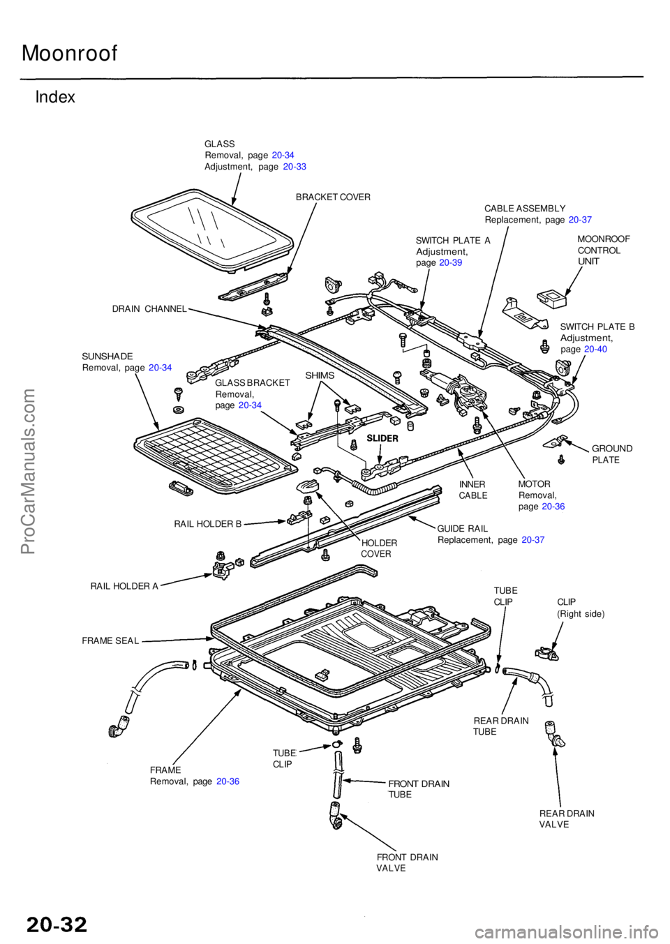
Moonroof
Index
GLAS S
Removal , pag e 20-3 4
Adjustment , pag e 20-3 3
BRACKE T COVE R
CABLE ASSEMBL Y
Replacement , pag e 20-3 7
SUNSHAD ERemoval, pag e 20-3 4 MOONROO
F
CONTRO L
UNIT
SWITC H PLAT E BAdjustment ,page 20-4 0
GROUN DPLATE
RAIL HOLDE R A
FRAM E SEA L TUB
E
CLI P CLI P
(Righ t side )
FRAM E
Removal , pag e 20-3 6
REAR DRAI N
VALV E
FRONT DRAI NVALVE
FRONT DRAI NTUBE
REA R DRAI N
TUB E
TUB ECLIP
GUID E RAI L
Replacement , pag e 20-3 7
MOTO
R
Removal ,
pag e 20-3 6
INNE
R
CABL E
HOLDE RCOVER
RAIL HOLDE R B
GLAS
S BRACKE T
Removal ,
pag e 20-3 4
SHIM S
DRAI N CHANNE L SWITC
H PLAT E A
Adjustment ,page 20-3 9
ProCarManuals.com
Page 1347 of 1954
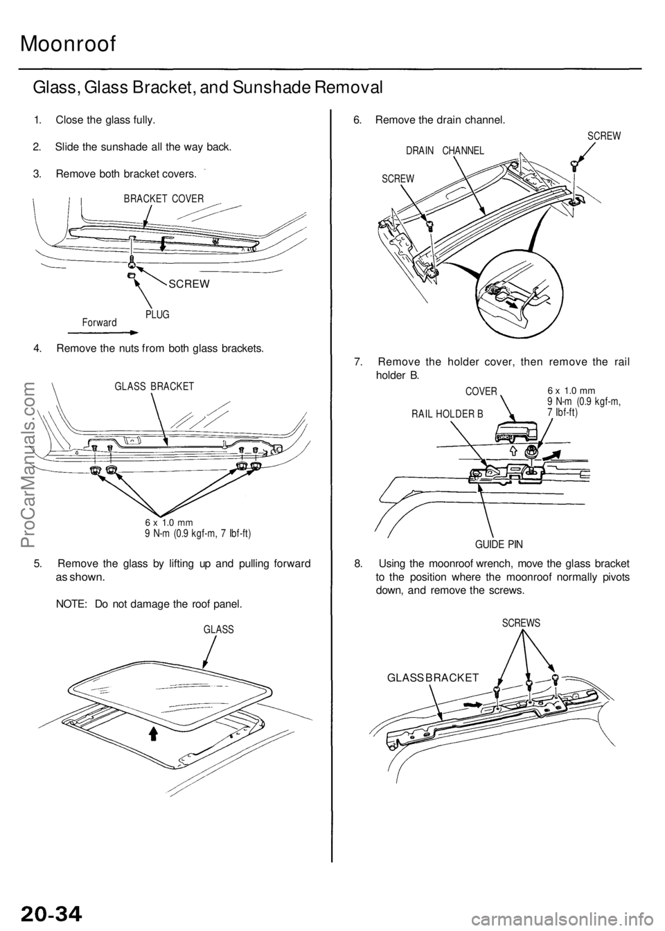
Moonroof
Glass, Glas s Bracket , an d Sunshad e Remova l
6. Remov e th e drai n channel.
DRAI N CHANNE L
SCREW
1. Clos e th e glas s fully .
2 . Slid e th e sunshad e al l th e wa y back .
3 . Remov e bot h bracke t covers .
BRACKE T COVE R
Forwar d PLU
G
4. Remov e th e nut s fro m bot h glas s brackets .
GLASS BRACKE T
6 x 1. 0 m m9 N- m (0. 9 kgf-m , 7 Ibf-ft )
5. Remov e th e glas s b y liftin g u p an d pullin g forwar d
as shown .
NOTE: D o no t damag e th e roo f panel .
GLASS SCRE
W
7. Remov e th e holde r cover , the n remov e th e rai l
holde r B .
6 x 1. 0 m m9 N- m (0. 9 kgf-m ,
7 Ibf-ft )
COVE
R
GUIDE PI N
8. Usin g th e moonroo f wrench , mov e th e glas s bracke t
t o th e positio n wher e th e moonroo f normall y pivot s
down , an d remov e th e screws .
SCREW S
GLASS BRACKE T
RAIL HOLDE R B
SCRE W
ProCarManuals.com