set clock ACURA RL KA9 1996 Service Repair Manual
[x] Cancel search | Manufacturer: ACURA, Model Year: 1996, Model line: RL KA9, Model: ACURA RL KA9 1996Pages: 1954, PDF Size: 61.44 MB
Page 230 of 1954
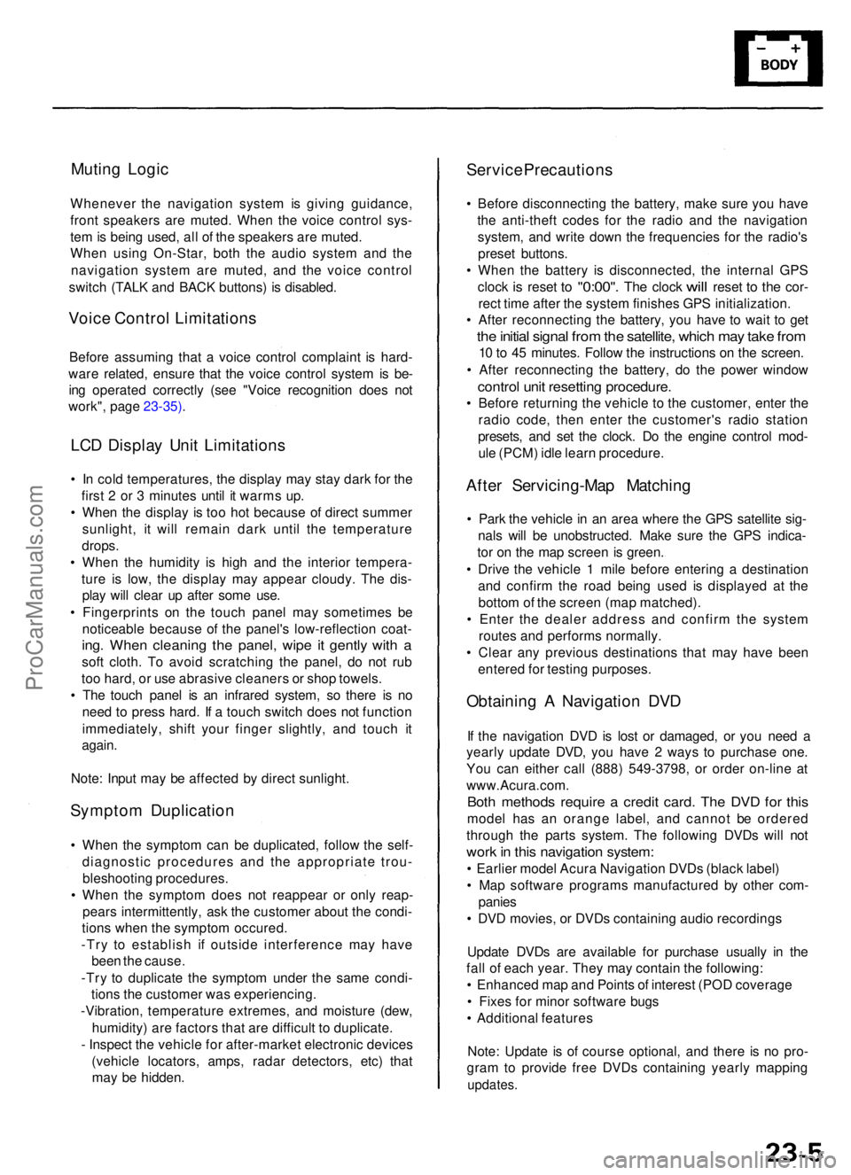
Muting Logi c
Wheneve r th e navigatio n syste m is givin g guidance ,
fron t speaker s ar e muted . Whe n th e voic e contro l sys -
te m is bein g used , al l o f th e speaker s ar e muted .
Whe n usin g On-Star , bot h th e audi o syste m an d th e
navigatio n syste m ar e muted , an d th e voic e contro l
switc h (TAL K an d BAC K buttons ) i s disabled .
Voice Contro l Limitation s
Before assumin g tha t a voic e contro l complain t i s hard -
war e related , ensur e tha t th e voic e contro l syste m is be -
in g operate d correctl y (se e "Voic e recognitio n doe s no t
work" , pag e 23-35) .
LCD Displa y Uni t Limitation s
• I n col d temperatures , th e displa y ma y sta y dar k fo r th e
firs t 2 o r 3 minute s unti l i t warm s up .
• Whe n th e displa y i s to o ho t becaus e o f direc t summe r
sunlight , i t wil l remai n dar k unti l th e temperatur e
drops .
• Whe n th e humidit y i s hig h an d th e interio r tempera -
tur e i s low , th e displa y ma y appea r cloudy . Th e dis -
pla y wil l clea r u p afte r som e use .
• Fingerprint s o n th e touc h pane l ma y sometime s b e
noticeabl e becaus e o f th e panel' s low-reflectio n coat -
ing. Whe n cleanin g th e panel , wip e i t gentl y wit h a
sof t cloth . T o avoi d scratchin g th e panel , d o no t ru b
to o hard , o r us e abrasiv e cleaner s o r sho p towels .
• Th e touc h pane l i s a n infrare d system , s o ther e i s n o
nee d t o pres s hard . I f a touc h switc h doe s no t functio n
immediately , shif t you r finge r slightly , an d touc h i t
again .
Note : Inpu t ma y b e affecte d b y direc t sunlight .
Symptom Duplicatio n
• Whe n th e sympto m ca n b e duplicated , follo w th e self -
diagnosti c procedure s an d th e appropriat e trou -
bleshootin g procedures .
• Whe n th e sympto m doe s no t reappea r o r onl y reap -
pear s intermittently , as k th e custome r abou t th e condi -
tion s whe n th e sympto m occured .
-Tr y t o establis h i f outsid e interferenc e ma y hav e
bee n th e cause .
-Tr y t o duplicat e th e sympto m unde r th e sam e condi -
tion s th e custome r wa s experiencing .
-Vibration , temperatur e extremes , an d moistur e (dew ,
humidity ) ar e factor s tha t ar e difficul t t o duplicate .
- Inspec t th e vehicl e fo r after-marke t electroni c device s
(vehicl e locators , amps , rada r detectors , etc) that
ma y b e hidden .
Service Precaution s
• Befor e disconnectin g th e battery , mak e sur e yo u hav e
th e anti-thef t code s fo r th e radi o an d th e navigatio n
system , an d writ e dow n th e frequencie s fo r th e radio' s
prese t buttons .
• Whe n th e batter y i s disconnected , th e interna l GP S
cloc k
is rese t to "0:00" . The cloc k will rese t to th e cor -
rec t tim e afte r th e syste m finishe s GP S initialization .
• Afte r reconnectin g th e battery , yo u hav e t o wai t t o ge t
the initia l signa l fro m th e satellite , whic h ma y tak e fro m
10 to 4 5 minutes . Follo w th e instruction s o n th e screen .
• Afte r reconnectin g th e battery , d o th e powe r windo w
control uni t resettin g procedure .
• Befor e returnin g th e vehicl e t o th e customer , ente r th e
radi o code , the n ente r th e customer' s radi o statio n
presets , an d se t th e clock . D o th e engin e contro l mod -
ul e (PCM ) idl e lear n procedure .
After Servicing-Ma p Matchin g
• Par k th e vehicl e in a n are a wher e th e GP S satellit e sig -
nal s wil l b e unobstructed . Mak e sur e th e GP S indica -
to r o n th e ma p scree n i s green .
• Driv e th e vehicl e 1 mil e befor e enterin g a destinatio n
an d confir m th e roa d bein g use d i s displaye d a t th e
botto m o f th e scree n (ma p matched) .
• Ente r th e deale r addres s an d confir m th e syste m
route s an d perform s normally .
• Clea r an y previou s destination s tha t ma y hav e bee n
entere d fo r testin g purposes .
Obtaining A Navigatio n DV D
If th e navigatio n DV D is los t o r damaged , o r yo u nee d a
yearl y updat e DVD , yo u hav e 2 way s t o purchas e one .
Yo u ca n eithe r cal l (888 ) 549-3798 , o r orde r on-lin e a t
www.Acura.com .
Both method s requir e a credi t card . Th e DV D fo r thi s
mode l ha s a n orang e label , an d canno t b e ordere d
throug h th e part s system . Th e followin g DVD s wil l no t
wor k in thi s navigatio n system :
• Earlie r mode l Acur a Navigatio n DVD s (blac k label )
• Ma p softwar e program s manufacture d b y othe r com -
panie s
• DV D movies , o r DVD s containin g audi o recording s
Updat e DVD s ar e availabl e fo r purchas e usuall y i n th e
fal l o f eac h year . The y ma y contai n th e following :
• Enhance d ma p an d Point s o f interes t (PO D coverag e
• Fixe s fo r mino r softwar e bug s
• Additiona l feature s
Note : Updat e i s o f cours e optional , an d ther e i s n o pro -
gra m to provid e fre e DVD s containin g yearl y mappin g
updates.
ProCarManuals.com
Page 271 of 1954

Navigation Syste m
System Diagnosi s Mod e (cont'd )
GPS Informatio n
This scree n show s th e curren t statu s o f GP S reception .
Th e circula r diagra m show s th e curren t locatio n o f th e
GP S satellite s (yello w numbers ) a s the y woul d appea r i n
th e sky . Th e oute r circl e represent s th e horizo n ( 0 degree s
elevation) . Th e middl e an d inne r circle s represent s 3 0
an d 6 0 degree s respectively . Th e ver y cente r o f th e dia -
gra m (9 0 degree s elevation ) i s directl y overhead .
Naturally, nearb y obstructions , lik e tal l building s wil l
bloc k satellite s i n tha t direction . Tha t i s wh y i t i s neces -
sar y t o b e i n a n ope n are a t o effectivel y troubleshoo t
GP S receptio n issues .
The satellit e number s show n o n th e diagra m corre -
spond t o th e "PRN " numbe r i n th e "GP S Details "
screen . Ther e ar e alway s 2 4 "active " GP S satellite s in
orbit . Becaus e satellite s fail , an d hav e t o b e remove d
fro m service , spare s ar e alway s parke d in orbit , read y t o
b e activated . Thi s is wh y th e PR N (satellit e ID number )
can be greate r tha n 24 .
NOTE : T o us e thi s scree n fo r troubleshooting , th e vehi -
cl e shoul d b e ou t sid e awa y fro m buildings , tal l trees ,
an d high-tensio n wire s fo r a t leas t 1 0 minute s wit h th e
engin e running . Also , mak e sur e th e rea r shel f i s fre e o f
loos e item s tha t ca n bloc k receptio n an d tha t th e trun k
li d is closed .
• Th e "Numbe r o f Satellites " bo x show s th e numbe r o f
acquire d satellite s (maximu m o f 12) . I t shoul d contai n
3 o r mor e icons . I f no t troubleshoo t fo r "GP S ico n i s
white " (se e pag e 23-32 ).
• Th e "Curren t Position " show s latitude , longitude , an d
elevatio n (i n meters) . I f ther e ar e les s tha n 3 satel -
lites , th e elevatio n ca n b e grossl y inaccurate .
• Th e Date/Tim e fiel d show s th e curren t date , an d als o
a tim e tha t include s dayligh t saving s an d othe r off -
set s entere d b y th e custome r i n Setu p scree n 2
"Adjus t Tim e Zone/Clock" .
GPS Detai l
By pressin g an d holdin g th e MEN U butto n fo r 1 0 sec -
onds , a GP S Detai l scree n is displayed . Thi s scree n dis -
play s rea l tim e incomin g satellit e positiona l data . Mos t
o f th e informatio n show n o n thi s scree n i s fo r factor y
use , howeve r som e o f th e dat a ca n indicat e partia l GP S
signa l interference .
• Th e bo x TS/A S an d HDop/VDo p is fo r factor y use .
• Th e Spee d an d Directio n informatio n i s update d i n
rea l tim e whe n driving , an d ca n b e use d t o detec t
intermitten t spee d senso r problems .
• Th e Date/Tim e Informatio n i s th e sam e a s i n Setu p
scree n 2 "Adjus t Tim e Zone/Clock" .
• I f th e "3D " ico n i s show n abov e th e yello w dots , thi s
implie s tha t a t leas t 4 satellite s ar e availabl e fo r ma p
positioning , an d th e "GPS " indicator on th e ma p
scree n wil l b e green . Se e th e "Globa l Positionin g
System " detaile d explanatio n i n th e "Syste m
Description" .
• I f th e ro w o f dat a i n th e tabl e belo w begin s wit h a
"yello w dot" , th e AZ I an d E L field s ca n b e use d t o
locat e eac h satellit e o n th e circula r GP S diagra m (se e
prio r screen) .
NOTE : Th e dat a belo w is a n exampl e only .
Th e tabl e o f value s show n o n th e scree n belo w ha s th e
followin g columns :
If "3D " i s missing , fol -
lo w troubleshootin g
(see pag e 23-32 ).
If al l 0 , then , follo w
troubleshootin g (se e
page 23-32 ).
ProCarManuals.com
Page 275 of 1954
Navigation System
System Diagnosis Mode (cont'd)
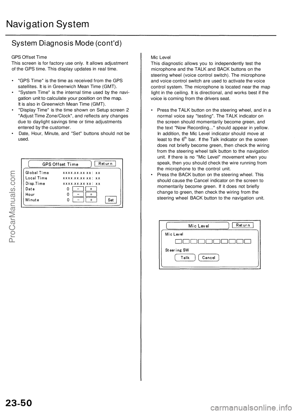
GPS Offset Time
This screen is for factory use only. It allows adjustment
of the GPS time. This display updates in real time.
• "GPS Time" is the time as received from the GPS
satellites. It is in Greenwich Mean Time (GMT).
• "System Time" is the internal time used by the navi-
gation unit to calculate your position on the map.
It is also in Greenwich Mean Time (GMT).
• "Display Time" is the time shown on Setup screen 2
"Adjust Time Zone/Clock", and reflects any changes
due to daylight savings time or time adjustments
entered by the customer.
• Date, Hour, Minute, and "Set" buttons should not be
used.
Mic Level
This diagnostic allows you to independently test the
microphone and the TALK and BACK buttons on the
steering wheel (voice control switch). The microphone
and voice control switch are used to activate the voice
control system. The microphone is located near the map
light in the ceiling. It is directional, and works best if the
voice is coming from the drivers seat.
• Press the TALK button on the steering wheel, and in a
normal voice say "testing". The TALK indicator on
the screen should momentarily become green, and
the text "Now Recording..." should appear in yellow.
In addition, the Mic Level indicator should move at
least to the 6th bar. If the Talk indicator on the screen
does not briefly become green, then check the wiring
from the steering wheel talk button to the navigation
unit. If there is no "Mic Level" movement when you
speak, then you should check the wire running from
the microphone to the control unit.
• Press the BACK button on the steering wheel. This
should cause the Cancel indicator on the screen to
momentarily become green. If it does not briefly
change to green, then check the wiring from the
steering wheel BACK button to the navigation unit.ProCarManuals.com
Page 759 of 1954
Troubleshooting Procedure s
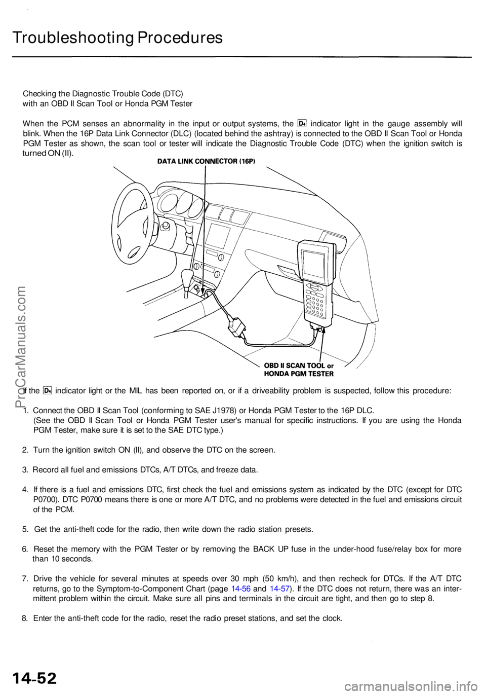
Checking th e Diagnosti c Troubl e Cod e (DTC )
wit h a n OB D II Sca n Too l o r Hond a PG M Teste r
When th e PC M sense s a n abnormalit y i n th e inpu t o r outpu t systems , th e indicato r ligh t i n th e gaug e assembl y wil l
blink . Whe n th e 16 P Dat a Lin k Connecto r (DLC ) (locate d behin d th e ashtray ) i s connecte d to th e OB D II Sca n Too l o r Hond a
PG M Teste r a s shown , th e sca n too l o r teste r wil l indicat e th e Diagnosti c Troubl e Cod e (DTC ) whe n th e ignitio n switc h i s
turne d O N (II) .
If th e indicato r ligh t o r th e MI L ha s bee n reporte d on , o r i f a driveabilit y proble m is suspected , follo w thi s procedure :
1 . Connec t th e OB D II Sca n Too l (conformin g to SA E J1978 ) o r Hond a PG M Teste r t o th e 16 P DLC .
(Se e th e OB D II Sca n Too l o r Hond a PG M Teste r user' s manua l fo r specifi c instructions . I f yo u ar e usin g th e Hond a
PG M Tester , mak e sur e it i s se t t o th e SA E DT C type. )
2 . Tur n th e ignitio n switc h O N (II) , an d observ e th e DT C o n th e screen .
3 . Recor d al l fue l an d emission s DTCs , A/ T DTCs , an d freez e data .
4 . I f ther e is a fue l an d emission s DTC , firs t chec k th e fue l an d emission s syste m a s indicate d b y th e DT C (excep t fo r DT C
P0700) . DT C P070 0 mean s ther e is on e o r mor e A/ T DTC , an d n o problem s wer e detecte d in th e fue l an d emission s circui t
of th e PCM .
5. Ge t th e anti-thef t cod e fo r th e radio , the n writ e dow n th e radi o statio n presets .
6 . Rese t th e memor y wit h th e PG M Teste r o r b y removin g th e BAC K U P fus e i n th e under-hoo d fuse/rela y bo x fo r mor e
tha n 1 0 seconds .
7 . Driv e th e vehicl e fo r severa l minute s a t speed s ove r 3 0 mp h (5 0 km/h) , an d the n rechec k fo r DTCs . I f th e A/ T DT C
returns , g o t o th e Symptom-to-Componen t Char t (pag e 14-5 6 an d 14-57 ). I f th e DT C doe s no t return , ther e wa s a n inter -
mitten t proble m withi n th e circuit . Mak e sur e al l pin s an d terminal s i n th e circui t ar e tight , an d the n g o t o ste p 8 .
8 . Ente r th e anti-thef t cod e fo r th e radio , rese t th e radi o prese t stations , an d se t th e clock .
ProCarManuals.com
Page 1366 of 1954
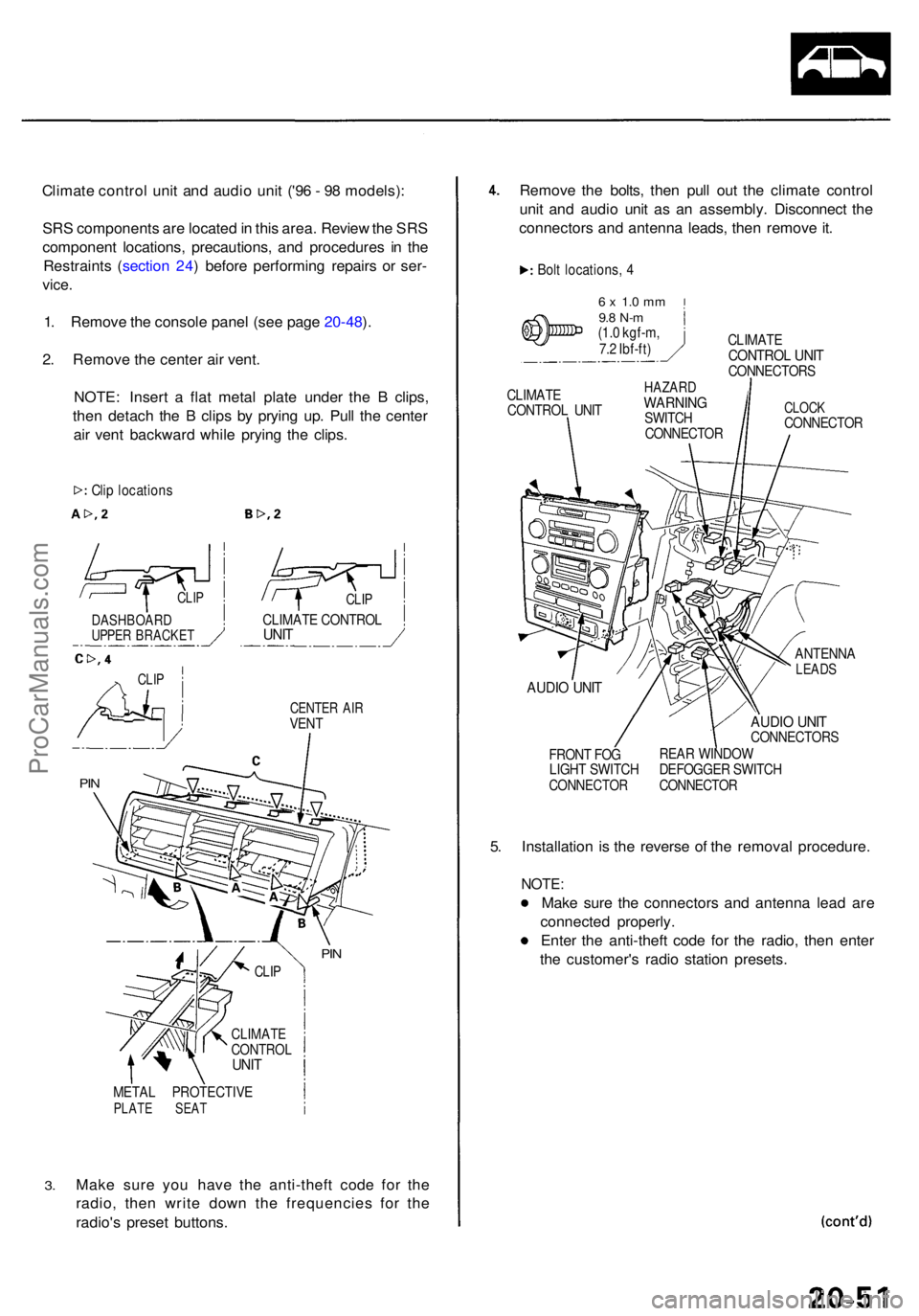
Climate contro l uni t an d audi o uni t ('9 6 - 9 8 models) :
SR S component s ar e locate d in thi s area . Revie w th e SR S
componen t locations , precautions , an d procedure s i n th e
Restraint s ( sectio n 24 ) befor e performin g repair s o r ser -
vice .
1. Remov e th e consol e pane l (se e pag e 20-48 ).
2 . Remov e th e cente r ai r vent .
NOTE : Inser t a fla t meta l plat e unde r th e B clips ,
the n detac h th e B clip s b y pryin g up . Pul l th e cente r
ai r ven t backwar d whil e pryin g th e clips .
CENTE R AI RVEN T
3.
META L PROTECTIV EPLATE SEA T
Make sur e yo u hav e th e anti-thef t cod e fo r th e
radio , the n writ e dow n th e frequencie s fo r th e
radio' s prese t buttons. Remov
e th e bolts , the n pul l ou t th e climat e contro l
uni t an d audi o uni t a s a n assembly . Disconnec t th e
connector s an d antenn a leads , the n remov e it .
Bol t locations , 4
6 x 1. 0 m m9.8 N- m(1.0 kgf-m ,
7. 2 Ibf-ft ) CLIMAT
E
CONTRO L UNI TCONNECTOR S
CLIMAT E
CONTRO L UNI THAZAR DWARNIN GSWITCH
CONNECTO RCLOCKCONNECTO R
AUDIO UNI T
FRON T FO G
LIGH T SWITC H
CONNECTO R
ANTENNALEADS
AUDIO UNI TCONNECTOR S
REA R WINDO W
DEFOGGE R SWITC H
CONNECTO R
5. Installatio n i s th e revers e o f th e remova l procedure .
NOTE:
Make sur e th e connector s an d antenn a lea d ar e
connecte d properly .
Ente r th e anti-thef t cod e fo r th e radio , the n ente r
th e customer' s radi o statio n presets .
Clip location s
CLIPCLIP
CLIMAT E CONTRO LUNITDASHBOAR DUPPER BRACKE T
CLIP
PIN
PIN
CLI P
CLIMAT ECONTRO LUNIT
ProCarManuals.com
Page 1367 of 1954
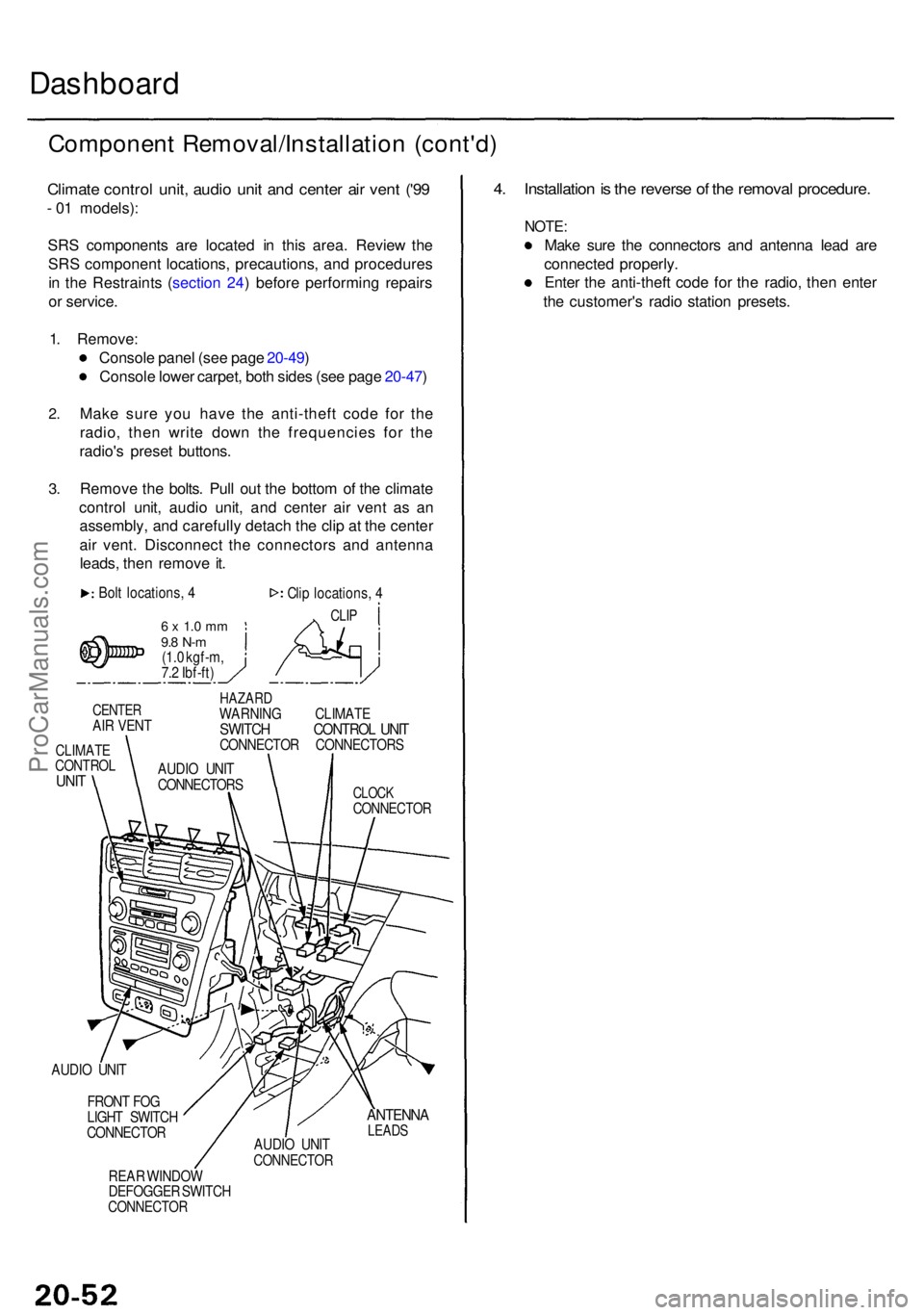
Dashboard
Componen t Removal/Installatio n (cont'd )
Climate contro l unit , audi o uni t an d cente r ai r ven t ('9 9
- 0 1 models) :
SR S component s ar e locate d i n thi s area . Revie w th e
SR S componen t locations , precautions , an d procedure s
i n th e Restraint s ( sectio n 24 ) befor e performin g repair s
o r service .
1 . Remove :
Consol e pane l (se e pag e 20-49 )
Consol e lowe r carpet , bot h side s (se e pag e 20-47 )
2.
3.
Mak e sur e yo u hav e th e anti-thef t cod e fo r th e
radio , the n writ e dow n th e frequencie s fo r th e
radio' s prese t buttons .
Remov e th e bolts . Pul l ou t th e botto m o f th e climat e
contro l unit , audi o unit , an d cente r ai r ven t a s a n
assembly , an d carefull y detac h th e cli p a t th e cente r
ai r vent . Disconnec t th e connector s an d antenn a
leads , the n remov e it .
Bol t locations , 4
6 x 1. 0 m m9.8 N- m(1.0 kgf-m ,
7. 2 Ibf-ft ) Cli
p locations , 4
CLI P
CENTE RAIR VEN T
CLIMAT ECONTRO LUNIT
HAZAR DWARNIN G CLIMAT ESWITCH CONTRO L UNI TCONNECTO R CONNECTOR S
CLOCKCONNECTO R
AUDIO UNI T
FRON T FO G
LIGH T SWITC H
CONNECTO R
REA R WINDO W
DEFOGGE R SWITC H
CONNECTO R
ANTENNALEADSAUDIO UNI TCONNECTO R
4. Installatio n is th e revers e o f th e remova l procedure .
NOTE:
Make sur e th e connector s an d antenn a lea d ar e
connecte d properly .
Ente r th e anti-thef t cod e fo r th e radio , the n ente r
th e customer' s radi o statio n presets .
AUDIO UNI T
CONNECTOR S
ProCarManuals.com
Page 1548 of 1954
Headlights
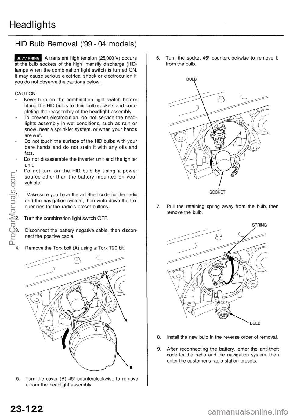
HID Bul b Remova l ('9 9 - 0 4 models )
A transien t hig h tensio n (25,00 0 V ) occur s
a t th e bul b socket s o f th e hig h intensit y discharg e (HID )
lamp s whe n th e combinatio n ligh t switc h is turne d ON .
I t ma y caus e seriou s electrica l shoc k o r electrocutio n if
yo u d o no t observ e th e caution s below .
CAUTION :
• Neve r tur n o n th e combinatio n ligh t switc h befor e
fittin g th e HI D bulb s t o thei r bul b socket s an d com -
pletin g th e reassembl y o f th e headligh t assembly .
• T o preven t electrocution , d o no t servic e th e head -
light s assembl y i n we t conditions , suc h a s rai n o r
snow , nea r a sprinkle r system , o r whe n you r hand s
are wet .
• D o no t touc h th e surfac e o f th e HI D bulb s wit h you r
bar e hand s an d d o no t stai n i t wit h an y oil s an d
fats .
• D o no t disassembl e th e inverte r uni t an d th e ignite r
unit .
• D o no t tur n o n th e HI D bul b b y usin g a powe r
sourc e othe r tha n th e batter y mounte d o n you r
vehicle .
1. Mak e sur e yo u hav e th e anti-thef t cod e fo r th e radi o
an d th e navigatio n system , the n writ e dow n th e fre -
quencie s fo r th e radio' s prese t buttons .
2. Tur n th e combinatio n ligh t switc h OFF .
3. Disconnec t th e batter y negativ e cable , the n discon -
nec t th e positiv e cable .
4 . Remov e th e Tor x bol t (A ) usin g a Tor x T2 0 bit .
5 . Tur n th e cove r (B ) 45 ° counterclockwis e t o remov e
i t fro m th e headligh t assembly . 8
. Instal l th e ne w bul b in th e revers e orde r o f removal .
9. Afte r reconnectin g th e battery , ente r th e anti-thef t
code fo r th e radi o an d th e navigatio n system , the n
ente r th e customer' s radi o statio n presets .
BULB
SPRIN G
6. Tur n th e socke t 45 ° counterclockwis e t o remov e i t
fro m th e bulb .
BULB
7. Pul l th e retainin g sprin g awa y fro m th e bulb , the n
remov e th e bulb .
SOCKE T
ProCarManuals.com
Page 1777 of 1954
Clock Displa y Siz e an d Locatio n Adjustmen t
'00 - 0 1 model s onl y
1. Tur n th e ignitio n switc h O N (II) .
2 . Whe n th e disclaime r i s show n o n th e navigatio n displa y unit , touc h "OK. "
3 . Whe n th e "Ente r destinatio n by: " scree n i s shown , touc h "Setup. "
4 . Whe n th e "Setu p Screen " i s shown , touc h Displa y "Off. "
5 . Touc h th e number s o f th e cloc k t o chang e th e cloc k siz e an d location .
• I f th e cloc k i s smal l an d i n th e lowe r righ t han d come r o f th e screen , i t wil l increas e in siz e an d mov e t o th e cente r o f
th e screen .
• I f th e cloc k i s larg e an d i n th e cente r o f th e screen , i t wil l decreas e i n siz e an d mov e t o th e lowe r righ t han d corne r o f
th e screen .
6 . Pus h th e MEN U butto n t o retur n t o th e "Ente r destinatio n by: " screen .
The cloc k displa y setting s wil l b e saved .
ProCarManuals.com
Page 1950 of 1954
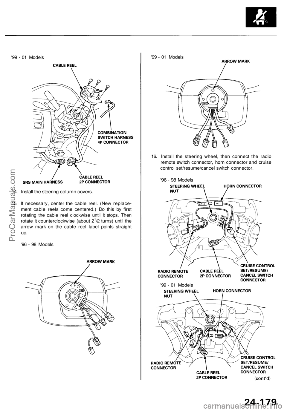
'99 - 01 Models
'99 - 01 Models
16. Install the steering wheel, then connect the radio
remote switch connector, horn connector and cruise
control set/resume/cancel switch connector.
'96 - 98 Models
14. Install the steering column covers.
15. If necessary, center the cable reel. (New replace-
ment cable reels come centered.) Do this by first
rotating the cable reel clockwise until it stops. Then
rotate it counterclockwise (about 21/2 turns) until the
arrow mark on the cable reel label points straight
up.
'96 - 98 Models
'99 - 01 ModelsProCarManuals.com