sensor ACURA RL KA9 1996 Service Repair Manual
[x] Cancel search | Manufacturer: ACURA, Model Year: 1996, Model line: RL KA9, Model: ACURA RL KA9 1996Pages: 1954, PDF Size: 61.44 MB
Page 40 of 1954
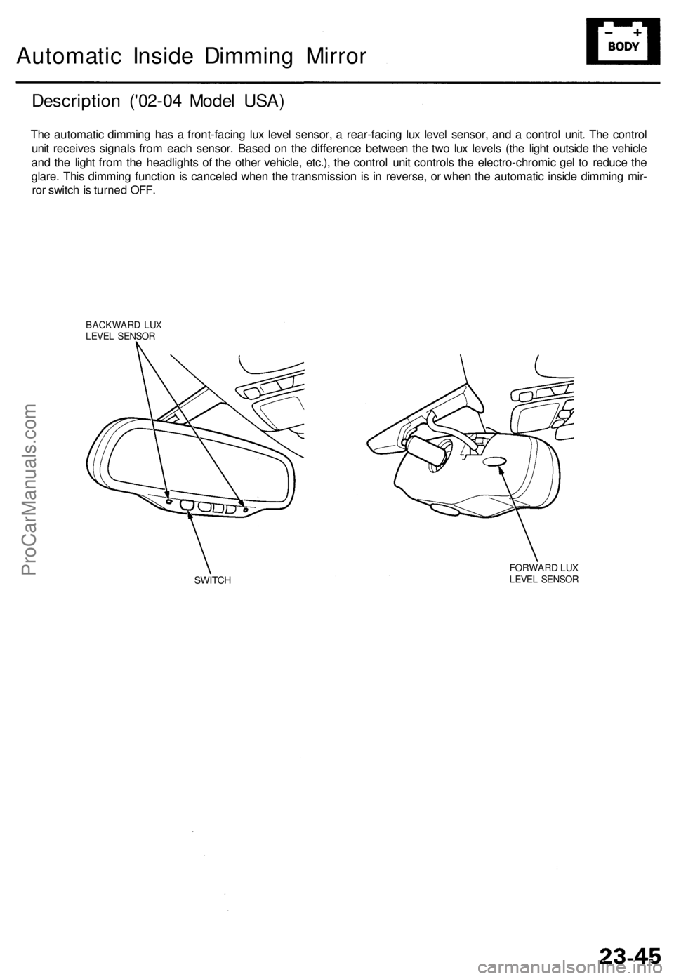
Automatic Insid e Dimmin g Mirro r
Descriptio n ('0 2-04 Mode l USA )
The automati c dimmin g ha s a front-facin g lu x leve l sensor , a rear-facin g lu x leve l sensor , an d a contro l unit . Th e contro l
uni t receive s signal s fro m eac h sensor . Base d o n th e differenc e betwee n th e tw o lu x level s (th e ligh t outsid e th e vehicl e
an d th e ligh t fro m th e headlight s o f th e othe r vehicle , etc.) , th e contro l uni t control s th e electro-chromi c ge l t o reduc e th e
glare . Thi s dimmin g functio n is cancele d whe n th e transmissio n i s i n reverse , o r whe n th e automati c insid e dimmin g mir -
ro r switc h is turne d OFF .
BACKWAR D LU XLEVE L SENSO R
SWITCHFORWAR D LU XLEVE L SENSO R
ProCarManuals.com
Page 134 of 1954

Troubleshooting
Diagnostic Troubl e Cod e (DTC ) Char t (cont'd )
DTC(MI L indication )
P0139 (63)*2
P014 1 (65 )
P0153 (61)*2
P015 4 (1 )
P015 5 (41 )
P017 1 (46)*
2
P017 2 (46)*2
P017 4 (45)*2
P017 5 (45)*2
P030 0
P0325 (53 )
P033 0 (23 )
Detection Ite m
Secondar y Heate d Oxyge n Senso r(Secondar y H02S ) Slo w Respons e
(Sensor 2 )
Secondar y Heate d Oxyge n
Senso r (Secondar y HO2S ) Heate r
Circui t Malfunctio n (Senso r 2 )
Lef t Primar y Heate d Oxyge n
Senso r (Lef t Primar y HO2S ) Slo w
Respons e (Ban k 2 , Senso r 1 )
Lef t Primar y Heate d Oxyge n
Senso r (Lef t Primar y HO2S )
Heater Syste m Malfunctio n
Left Primar y Heate d Oxyge n
Sensor (Lef t Primar y H02S )
Heate r Circui t Malfunctio n (Ban k
2 , Senso r 1 )
Fue l Syste m To o Lea n [Righ t
Ban k (Ban k 1) ]
Fue l Syste m To o Ric h [Righ t Ban k
(Ban k 1) ]
Fue l Syste m To o Lea n [Lef t Ban k
(Ban k 2) ]
Fue l Syste m To o Ric h [Lef t Ban k
(Ban k 2) ]
Rando m Misfir e
Right Knoc k Senso r (Ban k 1 )Circui t Malfunctio n
Left Knoc k Senso r (Ban k 2 )Circui t Malfunctio n
Probable Caus e
• Secondar y H02 S (Senso r 2 )
• Ope n o r shor t i n Secondar y H02 S
(Senso r 2 ) heate r circui t
• PC M
• Lef t Primar y H02 S (Ban k 2 , Senso r 1 )
• Exhaus t syste m
• Ope n i n Lef t Primar y H02 S (Ban k 2 ,
Senso r 1 ) circui t
• Lef t Primar y H02 S (Ban k 2 , Senso r 1 )
• PC M
• Ope n o r shor t i n Lef t Primar y HO2 S
(Ban k 2 , Senso r 1 ) heate r circui t
• PC M
• Fue l suppl y syste m
• Righ t Primar y H02 S (Ban k 1 , Senso r 1 )
• MA P senso r
• Contaminate d fue l
• Valv e clearanc e
• Exhaus t leakag e
• Fue l suppl y syste m
• Righ t Primar y HO2 S (Ban k 1 , Senso r 1 )
• MA P senso r
• Contaminate d fue l
• Valv e clearanc e
• Fue l suppl y syste m
• Lef t Primar y H02 S (Ban k 2 , Senso r 1 )
• MA P senso r
• Contaminate d fue l• Exhaus t leakag e
• Fue l suppl y syste m
• Lef t Primar y H02 S (Ban k 2 , Senso r 1 )
• MA P senso r
• Contaminate d fue l
• Ignitio n syste m
• Fue l suppl y syste m
• MA P senso r
• EG R syste m
• Contaminate d fue l• Lac k o f fue l
• Ope n o r shor t i n Righ t Knoc k Senso r
(Ban k 1 ) circui t
• Righ t Knoc k Senso r (Ban k 1 )
• PC M
• Ope n o r shor t i n Lef t Knoc k Senso r
(Bank 2 ) circui t• Lef t Knoc k Senso r (Ban k 2 )• PC M
Page
11-5 1
11-5 3
11-57
11-5 7
11-5 7
11-5 7
11-5 9
*2: Thes e DTC s requir e tw o "trips " o r tw o drivin g cycle s unles s th e SC S servic e connecto r i s connected .
11-90
11-91
11-91
11-95
11-95
ProCarManuals.com
Page 135 of 1954
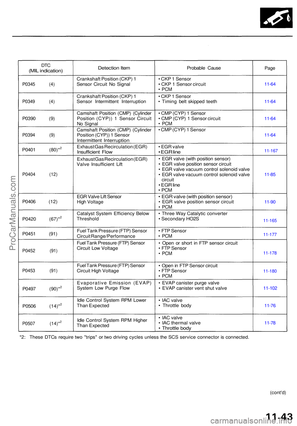
DTC(MI L indication )
P0345 (4 )
P0349 (4 )
P0390 (9 )
P0394 (9 )
P0401 (80)*2
P040 4 (12 )
P0406 (12 )
P042 0 (67)*
2
P045 1 (91 )
P0452 (91 )
P0453 (91 )
P0497 (90)*2
P050 6 (14)*2
P050 7 (14)*2
Detectio n Ite m
Crankshaf t Positio n (CKP ) 1
Senso r Circui t N o Signa l
Crankshaf t Positio n (CKP ) 1
Senso r Intermitten t Interruptio n
Camshaf t Positio n (CMP ) (Cylinde r
Positio n (CYP) ) 1 Senso r Circui t
N o Signa l
Camshaf t Positio n (CMP ) (Cylinde r
Positio n (CYP) ) 1 Senso r
Intermitten t Interruptio n
Exhaust Gas Recirculatio n (EGR )Insufficien t Flo w
Exhaus t Ga s Recirculatio n (EGR )
Valv e Insufficien t Lif t
EG R Valv e Lif t Senso r
High Voltag e
Catalys t Syste m Efficienc y Belo w
Threshol d
Fue l Tan k Pressur e (FTP ) Senso r
Circui t Range/Performanc e
Fue l Tan k Pressur e (FTP ) Senso r
Circui t Lo w Voltag e
Fue l Tan k Pressur e (FTP ) Senso r
Circui t Hig h Voltag e
Evaporativ e Emissio n (EVAP )
Syste m Lo w Purg e Flo w
Idl e Contro l Syste m RP M Lowe r
Tha n Expecte d
Idl e Contro l Syste m RP M Highe r
Tha n Expecte d Probabl
e Caus e
• CK P 1 Senso r
• CK P 1 Senso r circui t
• PC M
• CK P 1 Senso r
• Timin g bel t skippe d teet h
• CM P (CYP ) 1 Senso r
• CM P (CYP ) 1 Senso r circui t
• PC M
• CM P (CYP ) 1 Senso r
• EG R valv e
• EG R lin e
• EG R valv e (wit h positio n sensor )
• EG R valv e positio n senso r circui t
• EG R valv e vacuu m contro l solenoi d valv e
• EG R valv e vacuu m contro l solenoi d valv e
circui t
• EG R lin e• PC M
• EG R valv e (wit h positio n sensor )• EG R valv e positio n senso r circui t• PC M
• Thre e Wa y Catalyti c converte r
• Secondar y HO2 S
• FT P Senso r
• PC M
• Ope n o r shor t i n FT P senso r circui t
• FT P Senso r
• PC M
• Ope n in FT P Senso r circui t
• FT P Senso r
• PC M
• EVA P caniste r purg e valv e
• EVA P caniste r ven t shu t valv e
• IA C valv e
• Throttl e bod y
• IA C valv e
• IA C therma l valv e
• Throttl e bod y
Page
11-6 4
11-6 4
11-6 4
11-6 4
11-85
11-9 0
11-10 2
11-76
11-7 8
*2: Thes e DTC s requir e tw o "trips " o r tw o drivin g cycle s unles s th e SC S servic e connecto r i s connected .
(cont'd)
11-167
11-165
11-177
11-178
11-180
ProCarManuals.com
Page 137 of 1954
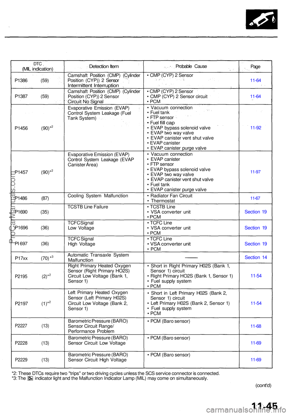
DTC(MIL indication )
P1386 (59 )
P138 7 (59 )
P145 6 (90)*
2
P145 7 (90)*2
P148 6 (87 )
P169 0 (35 )
P169 6 (36 )
PI 69 7 (36 )
P17xx (70 ) *3
P219 5 (2)*2
P219 7 (1)*2
P222 7 (13 )
P2228 (13 )
P2229 (13 )
Detection Ite m
Camshaf t Positio n (CMP ) (Cylinde r
Positio n (CYP) ) 2 Senso r
Intermitten t Interruptio n
Camshaft Positio n (CMP ) (Cylinde r
Positio n (CYP) ) 2 Senso r
Circuit N o Signa l
Evaporativ e Emissio n (EVAP )
Contro l Syste m Leakag e (Fue l
Tan k System )
Evaporativ e Emissio n (EVAP )
Contro l Syste m Leakag e (EVA P
Caniste r Area )
Coolin g Syste m Malfunctio n
TCST B Lin e Failur e
TCF C Signa l
Lo w Voltag e
TCF C Signa l
Hig h Voltag e
Automati c Transaxl e Syste m
Malfunctio n
Right Primar y Heate d Oxyge n
Senso r (Righ t Primar y HO2S )
Circui t Lo w Voltag e (Ban k 1 ,
Senso r 1 )
Lef t Primar y Heate d Oxyge n
Senso r (Lef t Primar y H02S )
Circui t Lo w Voltag e (Ban k 2 ,
Senso r 1 )
Barometri c Pressur e (BARO )
Senso r Circui t Range /
Performanc e Proble m
Barometri c Pressur e (BARO )
Senso r Circui t Lo w Voltag e
Barometri c Pressur e (BARO )
Senso r Circui t Hig h Voltag e Probabl
e Caus e
• CM P (CYP ) 2 Senso r
• CM P (CYP ) 2 Senso r
• CM P (CYP ) 2 Senso r circui t
• PC M
• Vacuu m connectio n
• Fue l tan k
• FT P senso r
• Fuel fill ca p• EVA P bypas s solenoi d valv e
• EVA P tw o wa y valv e
• EVA P caniste r ven t shu t valv e
• EVA P caniste r
• EVA P caniste r purg e valv e
• Vacuu m connectio n
• EVA P caniste r
• FT P senso r
• EVA P bypas s solenoi d valv e
• EVA P tw o wa y valv e
• EVA P caniste r ven t shu t valv e• Fue l tan k
• EVA P caniste r purg e valv e
• Radiato r Fa n Circui t
• Thermosta t
• TCST B Lin e
• VS A converte r uni t
• PC M
• TCF C Lin e
• VS A converte r uni t
• PC M
• TCF C Lin e• VS A converte r uni t• PC M
• Shor t i n Righ t Primar y H02 S (Ban k 1 ,
Senso r 1 ) circui t
• Righ t Primar y HO2 S (Ban k 1 , Senso r 1 )
• Fue l suppl y syste m
• PC M
• Shor t i n Lef t Primar y H02 S (Ban k 2 ,
Senso r 1 ) circui t
• Lef t Primar y H02 S (Ban k 2 , Senso r 1 )
• Fue l suppl y syste m
• PC M
• PC M (Bar o sensor )
• PC M (Bar o sensor )
• PC M (Bar o sensor ) Pag
e
11-6 4
11-6 4
11-9 2
11-97
11-6 7
Sectio n 1 9
Sectio n 1 9
Sectio n 1 9
Sectio n 1 4
11-5 4
11-5 4
11-6 8
11-6 9
11-6 9
*2: Thes e DTC s requir e tw o "trips " o r tw o drivin g cycle s unles s th e SC S servic e connecto r i s connected .*3: Th e indicato r ligh t an d th e Malfunctio n Indicato r Lam p (MIL ) ma y com e o n simultaneously .
(cont'd)
ProCarManuals.com
Page 138 of 1954
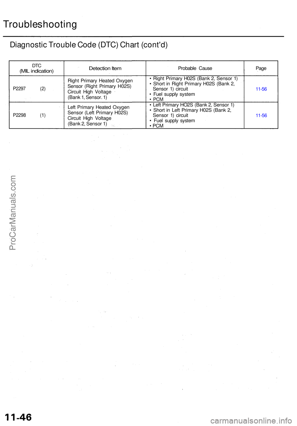
Troubleshooting
Diagnostic Troubl e Cod e (DTC ) Char t (cont'd )
DTC(MI L indication )
P2297 (2 )
P2298 (1 )
Detection Ite m
Righ t Primar y Heate d Oxyge n
Senso r (Righ t Primar y H02S )
Circui t Hig h Voltag e
(Ban k 1 , Sensor . 1 )
Lef t Primar y Heate d Oxyge n
Senso r (Lef t Primar y H02S )
Circui t Hig h Voltag e
(Ban k 2 , Senso r 1 ) Probabl
e Caus e
• Righ t Primar y H02 S (Ban k 2 , Senso r 1 )
• Shor t i n Righ t Primar y H02 S (Ban k 2 ,
Senso r 1 ) circui t
• Fue l suppl y syste m
• PC M
• Lef t Primar y HO2 S (Ban k 2 , Senso r 1 )
• Shor t i n Lef t Primar y H02 S (Ban k 2 ,
Senso r 1 ) circui t
• Fue l suppl y syste m
• PC M
Pag e
11-5 6
11-5 6
ProCarManuals.com
Page 139 of 1954
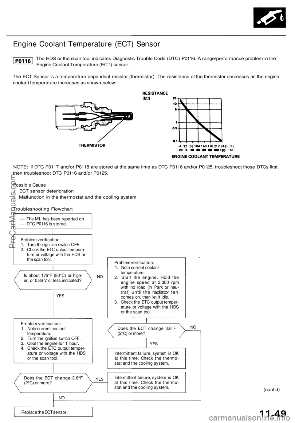
Engine Coolant Temperature (ECT) Sensor
The HDS or the scan tool indicates Diagnostic Trouble Code (DTC) P0116: A range/performance problem in the
Engine Coolant Temperature (ECT) sensor.
The ECT Sensor is a temperature dependent resistor (thermistor). The resistance of the thermistor decreases as the engine
coolant temperature increases as shown below.
NOTE: If DTC P0117 and/or P0118 are stored at the same time as DTC P0116 and/or P0125, troubleshoot those DTCs first,
then troubleshoot DTC P0116 and/or P0125.
Possible Cause
• ECT sensor deterioration
• Malfunction in the thermostat and the cooling system
Troubleshooting Flowchart
— The MIL has been reported on.
— DTC P0116 is stored.
Problem verification:
1. Turn the ignition switch OFF.
2. Check the ETC output tempera-
ture or voltage with the HDS or
the scan tool.
Is about 176°F (80°C) or high-
er, or 0.86 V or less indicated?
YES
Problem verification:
1. Note current coolant
temperature.
2. Turn the ignition switch OFF.
3. Cool the engine for 1 hour.
4. Check the ETC output temper-
ature or voltage with the HDS
or the scan tool.
Does the ECT change 3.6°F
(2°C) or more?
NO
Replace the ECT sensor.
NO
YES
Problem verification:
1. Note current coolant
temperature.
2. Start the engine. Hold the
engine speed at 3,000 rpm
with no load (in Park or neu-
tral)
until
the
radiator
fan
comes on, then let it idle.
3. Check the ETC output temper-
ature or voltage with the HDS
or the scan tool.
Does the ECT change 3.6°F
(2°C) or more?
NO
YES
Intermittent failure, system is OK
at this time. Check the thermo-
stat and the cooling system.
Intermittent failure, system is OK
at this time. Check the thermo-
stat and the cooling system.
(cont'd)ProCarManuals.com
Page 140 of 1954

PGM-FI System
Engine Coolant Temperature (ECT) Sensor (cont'd)
The HDS or the scan tool indicates Diagnostic Trouble Code (DTC) P0125: Engine Coolant Temperature
(ECT) sensor malfunction/slow response.
Is about 86°F (30°C) or less, or
2.61 V or higher indicated?
Intermittent failure, system is OK
at this time.
Check the thermostat and the
cooling system.
YES
Problem verification:
1. Let it idle for 6 minutes.
2. Check the ETC output temper-
ature or voltage with the HDS
or the scan tool.
Is about 86°F (30°C) or less, or
2.61 V or higher indicated?
Intermittent failure, system is OK
at this time.
Check the thermostat and the
cooling system.
YES
Replace the ECT sensor.
11-50
Problem verification:
1. Start the engine, and let it idle.
2. Check the ETC output temper-
ature or voltage with the HDS
or the scan tool.
— The MIL has been reported on
— DTC P0125 is stored.ProCarManuals.com
Page 141 of 1954
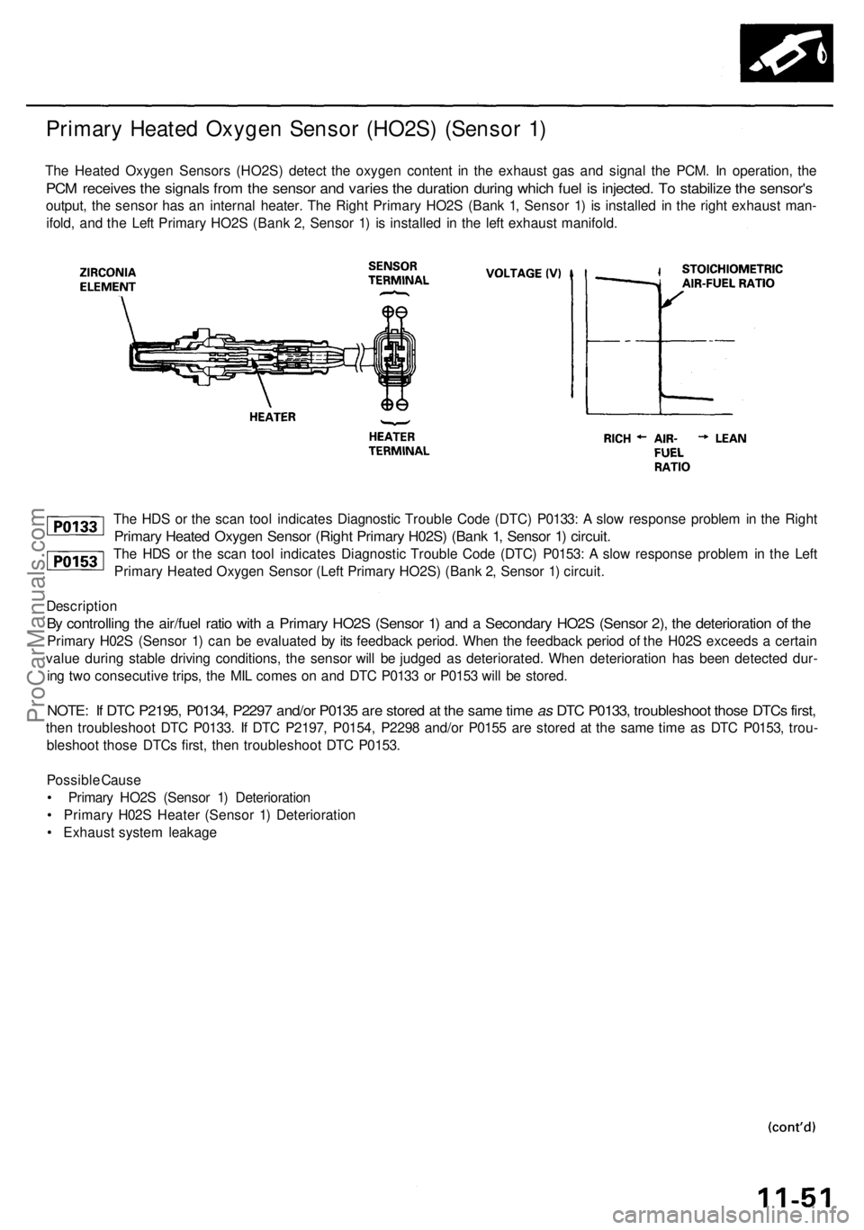
The HDS or the scan tool indicates Diagnostic Trouble Code (DTC) P0133: A slow response problem in the Right
Primary Heated Oxygen Sensor (Right Primary H02S) (Bank 1, Sensor 1) circuit.
The HDS or the scan tool indicates Diagnostic Trouble Code (DTC) P0153: A slow response problem in the Left
Primary Heated Oxygen Sensor (Left Primary HO2S) (Bank 2, Sensor 1) circuit.
Description
By controlling the air/fuel ratio with a Primary HO2S (Sensor 1) and a Secondary HO2S (Sensor 2), the deterioration of the
Primary H02S (Sensor 1) can be evaluated by its feedback period. When the feedback period of the H02S exceeds a certain
value during stable driving conditions, the sensor will be judged as deteriorated. When deterioration has been detected dur-
ing two consecutive trips, the MIL comes on and DTC P0133 or P0153 will be stored.
NOTE: If DTC P2195, P0134, P2297 and/or P0135 are stored at the same time as DTC P0133, troubleshoot those DTCs first,
then troubleshoot DTC P0133. If DTC P2197, P0154, P2298 and/or P0155 are stored at the same time as DTC P0153, trou-
bleshoot those DTCs first, then troubleshoot DTC P0153.
Possible Cause
• Primary HO2S (Sensor 1) Deterioration
• Primary H02S Heater (Sensor 1) Deterioration
• Exhaust system leakage
Primary Heated Oxygen Sensor (HO2S) (Sensor 1)
The Heated Oxygen Sensors (HO2S) detect the oxygen content in the exhaust gas and signal the PCM. In operation, the
PCM receives the signals from the sensor and varies the duration during which fuel is injected. To stabilize the sensor's
output, the sensor has an internal heater. The Right Primary HO2S (Bank 1, Sensor 1) is installed in the right exhaust man-
ifold, and the Left Primary HO2S (Bank 2, Sensor 1) is installed in the left exhaust manifold.ProCarManuals.com
Page 142 of 1954
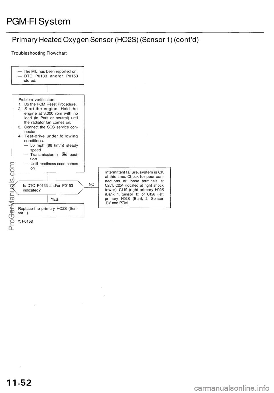
PGM-FI System
Primary Heated Oxygen Sensor (HO2S) (Sensor 1) (cont'd)
Troubleshooting Flowchart
Is DTC P0133 and/or P0153
indicated?
NO
YES
Intermittent failure, system is OK
at this time. Check for poor con-
nections or loose terminals at
C251, C254 (located at right shock
tower), C119 (right primary H02S
(Bank 1, Sensor 1)) or C126 (left
primary H02S (Bank 2, Sensor
1))*
and
PCM.
— The MIL has been reported on.
— DTC P0133 and/or P0153
stored.
Problem verification:
1. Do the PCM Reset Procedure.
2. Start the engine. Hold the
engine at 3,000 rpm with no
load (in Park or neutral) until
the radiator fan comes on.
3. Connect the SCS service con-
nector.
4. Test-drive under following
conditions.
— 55 mph (88 km/h) steady
speed
— Transmission in posi-
tion
— Until readiness code comes
on
Replace the primary HO2S (Sen-
sor 1).ProCarManuals.com
Page 143 of 1954
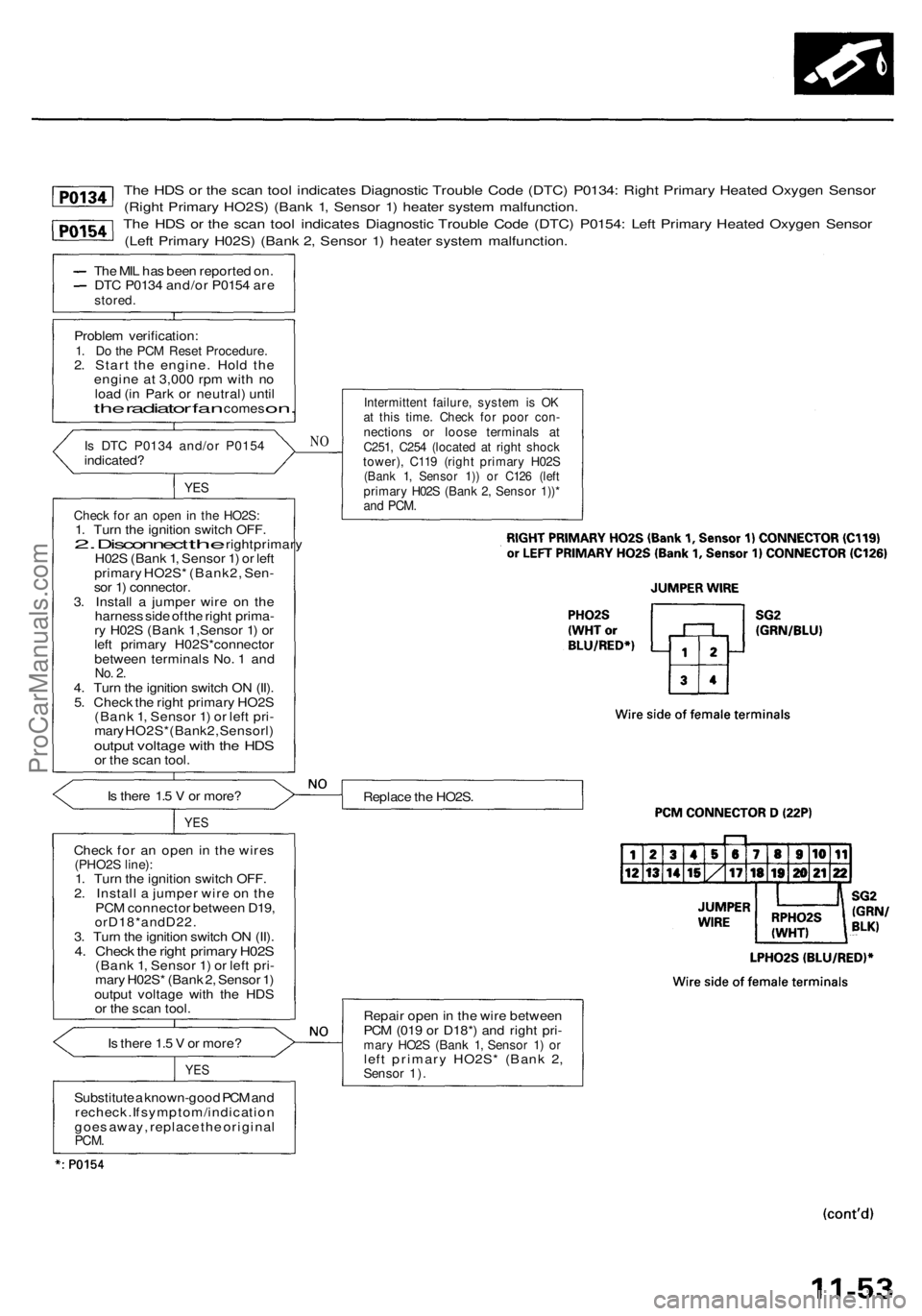
The HDS or the scan tool indicates Diagnostic Trouble Code (DTC) P0134: Right Primary Heated Oxygen Sensor
(Right Primary HO2S) (Bank 1, Sensor 1) heater system malfunction.
The HDS or the scan tool indicates Diagnostic Trouble Code (DTC) P0154: Left Primary Heated Oxygen Sensor
(Left Primary H02S) (Bank 2, Sensor 1) heater system malfunction.
The MIL has been reported on.
DTC P0134 and/or P0154 are
stored.
Problem verification:
1. Do the PCM Reset Procedure.
2. Start the engine. Hold the
engine at 3,000 rpm with no
load (in Park or neutral) until
the
radiator
fan
comes
on.
Is DTC P0134 and/or P0154
indicated?
YES
Check for an open in the HO2S:
1. Turn the ignition switch OFF.
2.
Disconnect
the
right primary
H02S (Bank 1, Sensor 1) or left
primary HO2S* (Bank2, Sen-
sor 1) connector.
3. Install a jumper wire on the
harness side of the right prima-
ry H02S (Bank 1,Sensor 1) or
left primary H02S*connector
between terminals No. 1 and
No. 2.
4. Turn the ignition switch ON (II).
5. Check the right primary HO2S
(Bank 1, Sensor 1) or left pri-
mary HO2S*(Bank2, Sensorl)
output voltage with the HDS
or the scan tool.
Is there 1.5 V or more?
YES
Check for an open in the wires
(PHO2S line):
1. Turn the ignition switch OFF.
2. Install a jumper wire on the
PCM connector between D19,
orD18*andD22.
3. Turn the ignition switch ON (II).
4. Check the right primary H02S
(Bank 1, Sensor 1) or left pri-
mary H02S* (Bank 2, Sensor 1)
output voltage with the HDS
or the scan tool.
Is there 1.5 V or more?
YES
NO
Intermittent failure, system is OK
at this time. Check for poor con-
nections or loose terminals at
C251, C254 (located at right shock
tower), C119 (right primary H02S
(Bank 1, Sensor 1)) or C126 (left
primary H02S (Bank 2, Sensor 1))*
and
PCM.
Replace the HO2S.
Repair open in the wire between
PCM (019 or D18*) and right pri-
mary HO2S (Bank 1, Sensor 1) or
left primary HO2S* (Bank 2,
Sensor 1).
Substitute a known-good PCM and
recheck. If symptom/indication
goes away, replace the original
PCM.ProCarManuals.com