steering ACURA TL 1995 Service Owner's Guide
[x] Cancel search | Manufacturer: ACURA, Model Year: 1995, Model line: TL, Model: ACURA TL 1995Pages: 1771, PDF Size: 62.49 MB
Page 671 of 1771
General Info
Specifications
Maintenance
Engine
Cooling
Fuel and Emissions
2.5L
3.2L
* Transaxle
SteeringSuspension
* Brakes (Including ABS)
* Body
* Heating, Ventilation
and Air Conditioning
* Body Electrical
* Engine Electrical
* SRS2.5L
3.2L
1995±98 TL Main Menu
As sections w/ * include SRS components, special precautions are required when servicing.
ProCarManuals.com
Page 682 of 1771
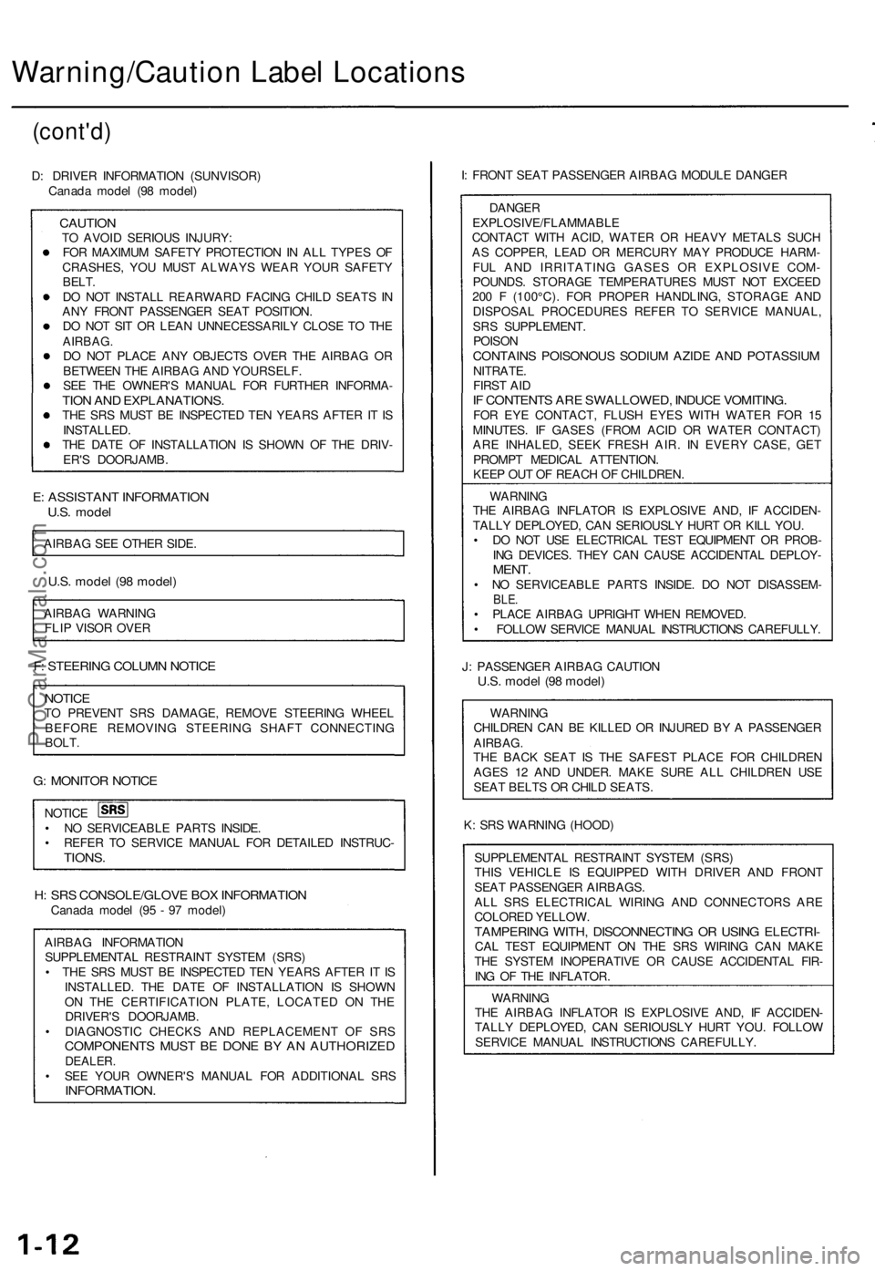
Warning/Caution Label Locations
(cont'd)
D: DRIVER INFORMATION (SUNVISOR)
Canada model (98 model)
CAUTION
TO AVOID SERIOUS INJURY:
FOR MAXIMUM SAFETY PROTECTION IN ALL TYPES OF
CRASHES, YOU MUST ALWAYS WEAR YOUR SAFETY
BELT.
DO NOT INSTALL REARWARD FACING CHILD SEATS IN
ANY FRONT PASSENGER SEAT POSITION.
DO NOT SIT OR LEAN UNNECESSARILY CLOSE TO THE
AIRBAG.
DO NOT PLACE ANY OBJECTS OVER THE AIRBAG OR
BETWEEN THE AIRBAG AND YOURSELF.
SEE THE OWNER'S MANUAL FOR FURTHER INFORMA-
TION AND EXPLANATIONS.
THE SRS MUST BE INSPECTED TEN YEARS AFTER IT IS
INSTALLED.
THE DATE OF INSTALLATION IS SHOWN OF THE DRIV-
ER'S DOORJAMB.
E: ASSISTANT INFORMATION
U.S. model
AIRBAG SEE OTHER SIDE.
U.S. model (98 model)
AIRBAG WARNING
FLIP VISOR OVER
F: STEERING COLUMN NOTICE
NOTICE
TO PREVENT SRS DAMAGE, REMOVE STEERING WHEEL
BEFORE REMOVING STEERING SHAFT CONNECTING
BOLT.
G: MONITOR NOTICE
NOTICE
• NO SERVICEABLE PARTS INSIDE.
• REFER TO SERVICE MANUAL FOR DETAILED INSTRUC-
TIONS.
H: SRS CONSOLE/GLOVE BOX INFORMATION
Canada model (95 - 97 model)
AIRBAG INFORMATION
SUPPLEMENTAL RESTRAINT SYSTEM (SRS)
• THE SRS MUST BE INSPECTED TEN YEARS AFTER IT IS
INSTALLED. THE DATE OF INSTALLATION IS SHOWN
ON THE CERTIFICATION PLATE, LOCATED ON THE
DRIVER'S DOORJAMB.
• DIAGNOSTIC CHECKS AND REPLACEMENT OF SRS
COMPONENTS MUST BE DONE BY AN AUTHORIZED
DEALER.
• SEE YOUR OWNER'S MANUAL FOR ADDITIONAL SRS
INFORMATION.
I: FRONT SEAT PASSENGER AIRBAG MODULE DANGER
DANGER
EXPLOSIVE/FLAMMABLE
CONTACT WITH ACID, WATER OR HEAVY METALS SUCH
AS COPPER, LEAD OR MERCURY MAY PRODUCE HARM-
FUL AND IRRITATING GASES OR EXPLOSIVE COM-
POUNDS. STORAGE TEMPERATURES MUST NOT EXCEED
200 F (100°C). FOR PROPER HANDLING, STORAGE AND
DISPOSAL PROCEDURES REFER TO SERVICE MANUAL,
SRS SUPPLEMENT.
POISON
CONTAINS POISONOUS SODIUM AZIDE AND POTASSIUM
NITRATE.
FIRST AID
IF CONTENTS ARE SWALLOWED, INDUCE VOMITING.
FOR EYE CONTACT, FLUSH EYES WITH WATER FOR 15
MINUTES. IF GASES (FROM ACID OR WATER CONTACT)
ARE INHALED, SEEK FRESH AIR. IN EVERY CASE, GET
PROMPT MEDICAL ATTENTION.
KEEP OUT OF REACH OF CHILDREN.
WARNING
THE AIRBAG INFLATOR IS EXPLOSIVE AND, IF ACCIDEN-
TALLY DEPLOYED, CAN SERIOUSLY HURT OR KILL YOU.
• DO NOT USE ELECTRICAL TEST EQUIPMENT OR PROB-
ING DEVICES. THEY CAN CAUSE ACCIDENTAL DEPLOY-
MENT.
• NO SERVICEABLE PARTS INSIDE. DO NOT DISASSEM-
BLE.
• PLACE AIRBAG UPRIGHT WHEN REMOVED.
• FOLLOW SERVICE MANUAL INSTRUCTIONS CAREFULLY.
J: PASSENGER AIRBAG CAUTION
U.S. model (98 model)
WARNING
CHILDREN CAN BE KILLED OR INJURED BY A PASSENGER
AIRBAG.
THE BACK SEAT IS THE SAFEST PLACE FOR CHILDREN
AGES 12 AND UNDER. MAKE SURE ALL CHILDREN USE
SEAT BELTS OR CHILD SEATS.
K: SRS WARNING (HOOD)
SUPPLEMENTAL RESTRAINT SYSTEM (SRS)
THIS VEHICLE IS EQUIPPED WITH DRIVER AND FRONT
SEAT PASSENGER AIRBAGS.
ALL SRS ELECTRICAL WIRING AND CONNECTORS ARE
COLORED YELLOW.
TAMPERING WITH, DISCONNECTING OR USING ELECTRI-
CAL TEST EQUIPMENT ON THE SRS WIRING CAN MAKE
THE SYSTEM INOPERATIVE OR CAUSE ACCIDENTAL FIR-
ING OF THE INFLATOR.
WARNING
THE AIRBAG INFLATOR IS EXPLOSIVE AND, IF ACCIDEN-
TALLY DEPLOYED, CAN SERIOUSLY HURT YOU. FOLLOW
SERVICE MANUAL INSTRUCTIONS CAREFULLY.ProCarManuals.com
Page 698 of 1771
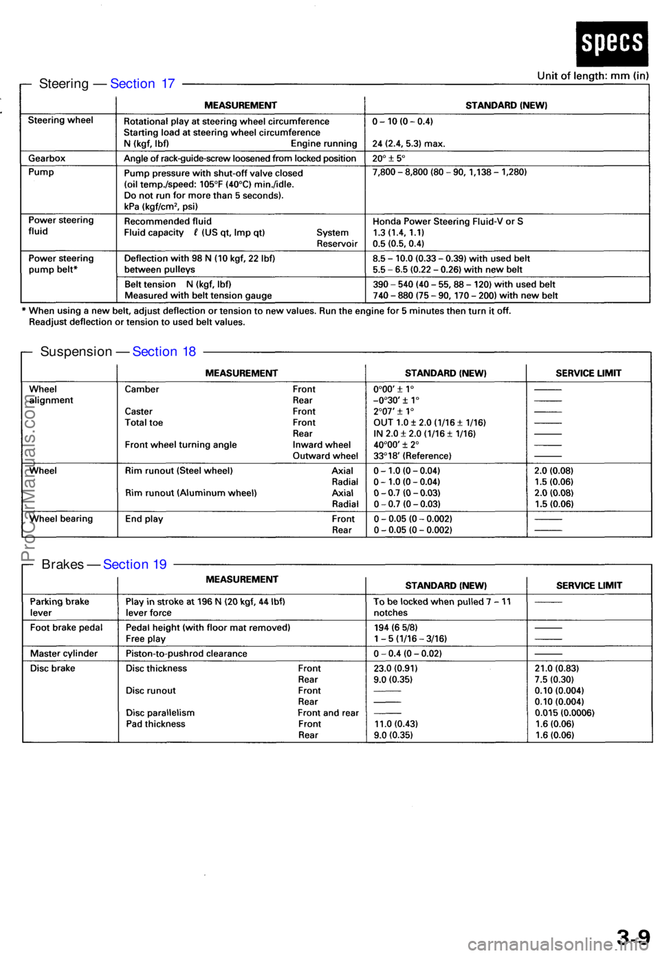
Steering — Sectio n 1 7
Suspensio n — Sectio n 1 8
Brake s — Sectio n 1 9
ProCarManuals.com
Page 720 of 1771
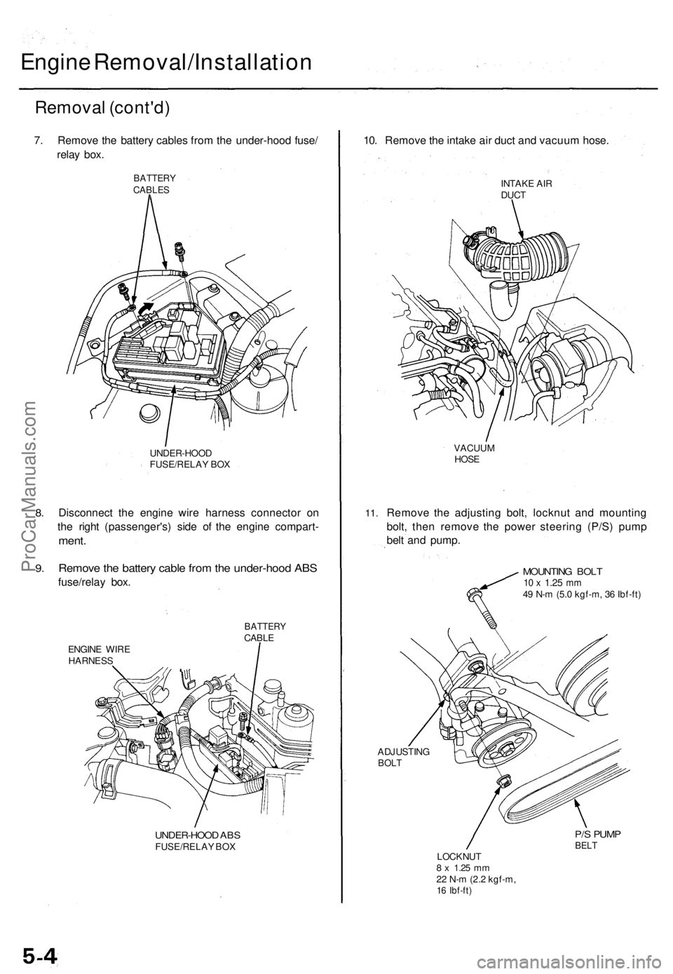
Engine Removal/Installation
Removal (cont'd)
7. Remove the battery cables from the under-hood fuse/
relay box.
BATTERY
CABLES
8.
9.
UNDER-HOOD
FUSE/RELAY BOX
Disconnect the engine wire harness connector on
the right (passenger's) side of the engine compart-
ment.
Remove the battery cable from the under-hood ABS
fuse/relay box.
BATTERY
CABLE
ENGINE WIRE
HARNESS
UNDER-HOOD ABS
FUSE/RELAY BOX
10. Remove the intake air duct and vacuum hose.
INTAKE AIR
DUCT
11.
VACUUM
HOSE
Remove the adjusting bolt, locknut and mounting
bolt, then remove the power steering (P/S) pump
belt and pump.
MOUNTING BOLT
10 x
1.25
mm
49 N-m (5.0 kgf-m, 36 Ibf-ft)
ADJUSTING
BOLT
P/S PUMP
BELT
LOCKNUT
8 x
1.25
mm
22 N-m (2.2 kgf-m,
16 Ibf-ft)ProCarManuals.com
Page 1144 of 1771
Component Location s
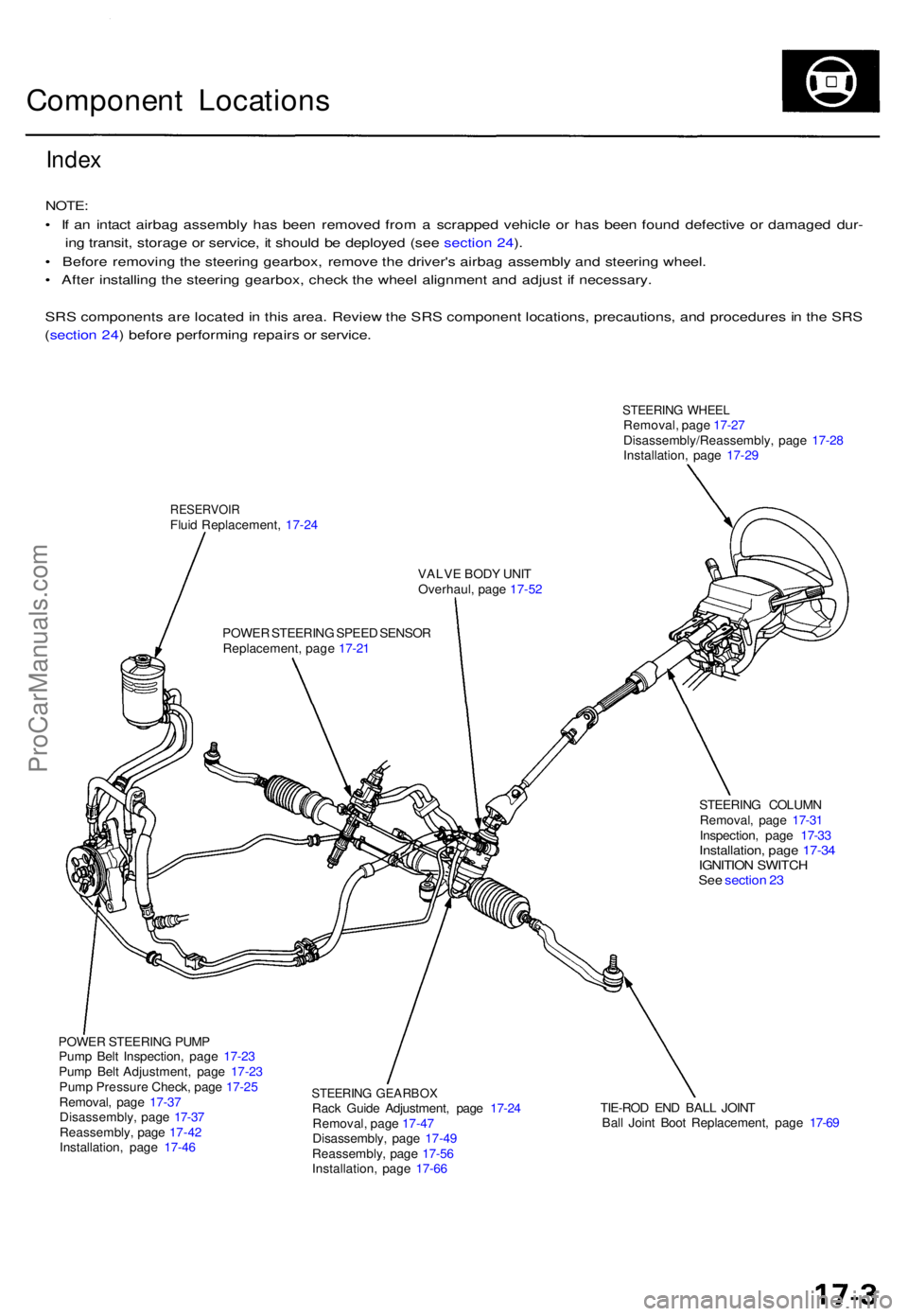
Index
NOTE :
• I f a n intac t airba g assembl y ha s bee n remove d fro m a scrappe d vehicl e o r ha s bee n foun d defectiv e o r damage d dur -
in g transit , storag e o r service , i t shoul d b e deploye d (se e sectio n 24 ).
• Befor e removin g th e steerin g gearbox , remov e th e driver' s airba g assembl y an d steerin g wheel .
• Afte r installin g th e steerin g gearbox , chec k th e whee l alignmen t an d adjus t i f necessary .
SR S component s ar e locate d in thi s area . Revie w th e SR S componen t locations , precautions , an d procedure s in th e SR S
( sectio n 24 ) befor e performin g repair s o r service .
STEERIN G WHEE LRemoval , pag e 17-2 7
Disassembly/Reassembly , pag e 17-2 8
Installation , pag e 17-2 9
RESERVOI RFluid Replacement , 17-2 4
VALVE BOD Y UNI T
Overhaul , pag e 17-5 2
POWE R STEERIN G SPEE D SENSO R
Replacement , pag e 17-2 1
STEERING COLUM N
Removal , pag e 17-3 1
Inspection , pag e 17-3 3
Installation , pag e 17-3 4IGNITIO N SWITC HSee sectio n 2 3
POWE R STEERIN G PUM P
Pum p Bel t Inspection , pag e 17-2 3
Pum p Bel t Adjustment , pag e 17-2 3
Pum p Pressur e Check , pag e 17-2 5
Removal , pag e 17-3 7
Disassembly , pag e 17-3 7
Reassembly , pag e 17-4 2
Installation , pag e 17-4 6
STEERIN G GEARBO XRack Guid e Adjustment , pag e 17-2 4
Removal , pag e 17-4 7
Disassembly , pag e 17-4 9
Reassembly , pag e 17-5 6
Installation , pag e 17-6 6 TIE-RO
D EN D BAL L JOIN T
Bal l Join t Boo t Replacement , pag e 17-6 9
ProCarManuals.com
Page 1145 of 1771
System Descriptio n
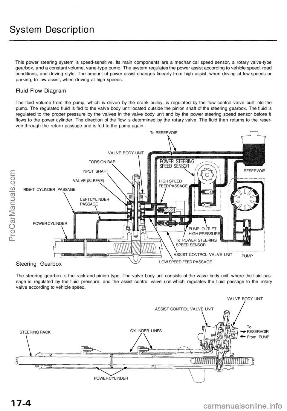
This powe r steerin g syste m is speed-sensitive . It s mai n component s ar e a mechanica l spee d sensor , a rotar y valve-typ e
gearbox, an d a constan t volume , vane-typ e pump . Th e syste m regulate s th e powe r assis t accordin g to vehicl e speed , roa d
conditions , an d drivin g style . Th e amoun t o f powe r assis t change s linearl y fro m hig h assist , whe n drivin g a t lo w speed s o r
parking , t o lo w assist , whe n drivin g a t hig h speeds .
Fluid Flo w Diagra m
The flui d volum e fro m th e pump , whic h i s drive n b y th e cran k pulley , i s regulate d b y th e flo w contro l valv e buil t int o th e
pump . Th e regulate d flui d i s fe d t o th e valv e bod y uni t locate d outsid e th e pinio n shaf t o f th e steerin g gearbox . Th e flui d i s
regulate d t o th e prope r pressur e b y th e valve s i n th e valv e bod y uni t an d b y th e powe r steerin g spee d senso r befor e it
flow s t o th e powe r cylinder . Th e directio n o f th e flo w is determine d b y th e rotar y valve . Th e flui d the n returns to th e reser -
voi r throug h th e retur n passag e an d i s fe d t o th e pum p again .
To RESERVOI R
VALVE BOD Y UNI T
TORSIO N BA R
INPU T SHAF T
VALVE (SLEEVE )
RIGHT CYLINDE R PASSAG E
POWE R CYLINDE R
Steering Gearbo xLOW SPEE D FEE D PASSAG E
The steerin g gearbo x i s th e rack-and-pinio n type . Th e valv e bod y uni t consist s o f th e valv e bod y unit , wher e th e flui d pas -
sag e i s regulate d b y th e flui d pressure , an d th e assis t contro l valv e uni t whic h regulate s th e flui d passag e t o th e rotar y
valv e accordin g t o vehicl e speed .
ASSIST CONTRO L VALV E UNI T
STEERIN G RAC K VALV
E BOD Y UNI T
ToRESERVOI R
From PUM P
POWE R CYLINDE RCYLINDE
R LINE S ASSIS
T CONTRO L VALV E UNI T
PUM P
To POWE R STEERIN G
SPEE D SENSO R
PUM
P OUTLE T
HIGH-PRESSUR E
HIGH SPEE D
FEE D PASSAG E
POWER STEERIN G
SPEE D SENSO R
RESERVOI R
LEFT CYLINDE R
PASSAG E
ProCarManuals.com
Page 1146 of 1771
Steering Pum p
Constructio n
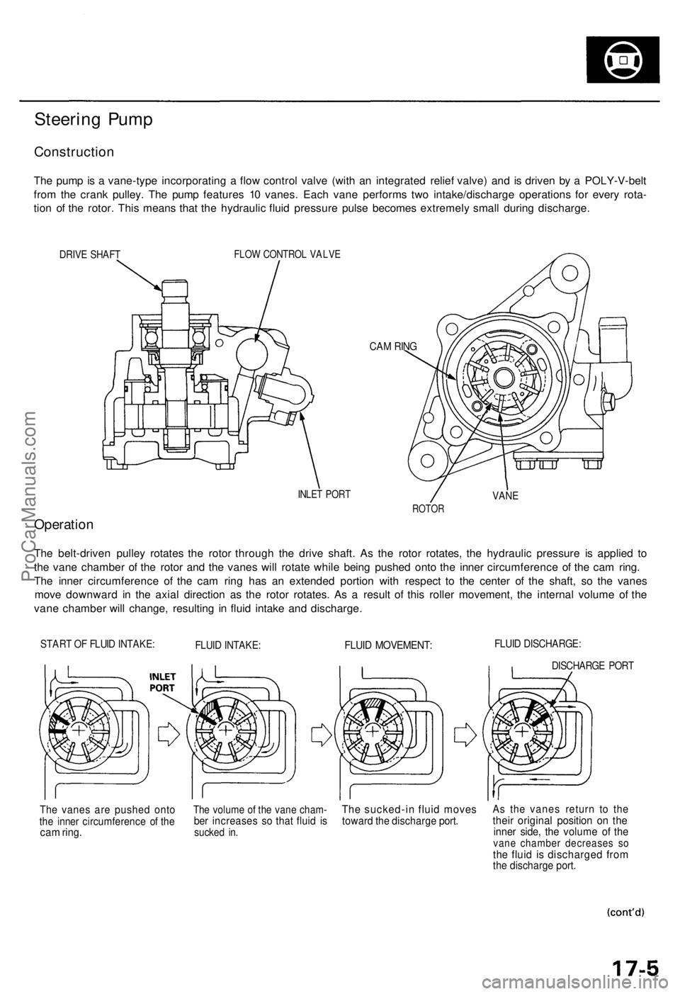
The pum p is a vane-typ e incorporatin g a flo w contro l valv e (wit h a n integrate d relie f valve ) an d i s drive n b y a POLY-V-bel t
fro m th e cran k pulley . Th e pum p feature s 1 0 vanes . Eac h van e perform s tw o intake/discharg e operation s fo r ever y rota -
tio n o f th e rotor . Thi s mean s tha t th e hydrauli c flui d pressur e puls e become s extremel y smal l durin g discharge .
DRIVE SHAF TFLOW CONTRO L VALV E
CAM RIN G
INLE T POR TVANE
ROTO R
Operatio n
The belt-drive n pulle y rotate s th e roto r throug h th e driv e shaft . A s th e roto r rotates , th e hydrauli c pressur e i s applie d t o
th e van e chambe r o f th e roto r an d th e vane s wil l rotat e whil e bein g pushe d ont o th e inne r circumferenc e o f th e ca m ring .
Th e inne r circumferenc e o f th e ca m rin g ha s a n extende d portio n wit h respec t t o th e cente r o f th e shaft , s o th e vane s
mov e downwar d i n th e axia l directio n a s th e roto r rotates . A s a resul t o f thi s rolle r movement , th e interna l volum e o f th e
van e chambe r wil l change , resultin g i n flui d intak e an d discharge .
START O F FLUI D INTAKE :FLUID INTAKE :FLUID MOVEMENT :FLUID DISCHARGE :
DISCHARGE POR T
The vane s ar e pushe d ont othe inne r circumferenc e o f th ecam ring .
The volum e o f th e van e cham -ber increase s s o tha t flui d i ssucke d in .
Th e sucked-i n flui d move stoward th e discharg e port .As th e vane s retur n t o th ethei r origina l positio n o n th einne r side , th e volum e o f th evan e chambe r decrease s s othe flui d i s discharge d fro mthe discharg e port .
ProCarManuals.com
Page 1147 of 1771
System Descriptio n
Steering Pum p (cont'd )
Flow Contro l
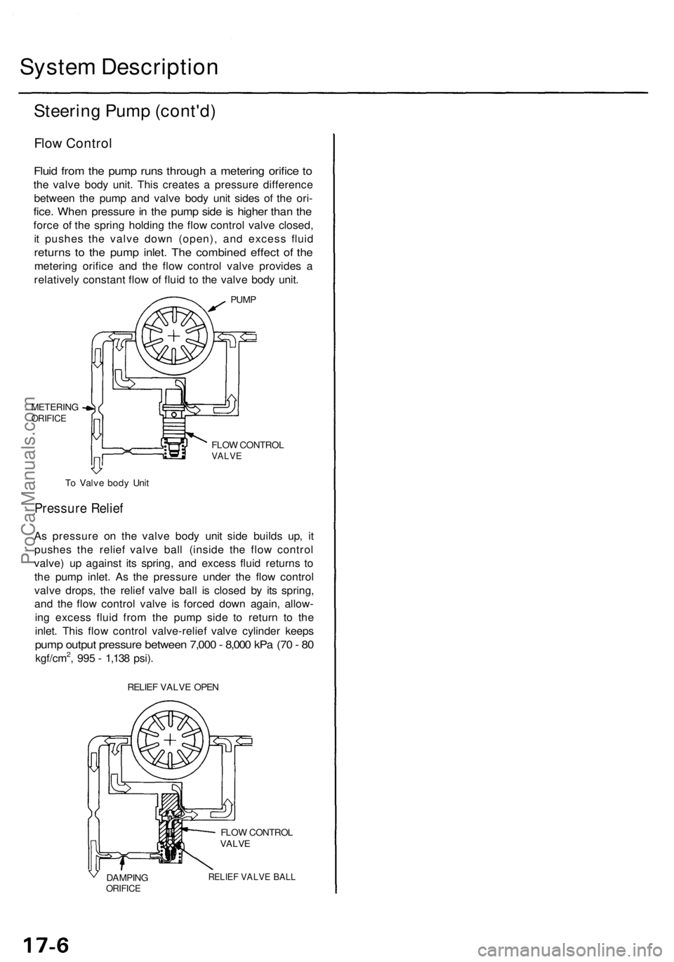
Fluid fro m th e pum p run s throug h a meterin g orific e to
th e valv e bod y unit . Thi s create s a pressur e differenc e
betwee n th e pum p an d valv e bod y uni t side s o f th e ori -
fice. Whe n pressur e in th e pum p sid e is highe r tha n th e
forc e o f th e sprin g holdin g th e flo w contro l valv e closed ,
i t pushe s th e valv e dow n (open) , an d exces s flui d
return s t o th e pum p inlet . Th e combine d effec t o f th e
meterin g orific e an d th e flo w contro l valv e provide s a
relativel y constan t flo w o f flui d t o th e valv e bod y unit .
PUM P
FLO W CONTRO L
VALVE
RELIEF VALV E OPE N
DAMPIN G
ORIFICE
FLOW CONTRO L
VALV E
RELIE F VALV E BAL L
METERIN GORIFICE
To Valv e bod y Uni t
Pressur e Relie f
As pressur e o n th e valv e bod y uni t sid e build s up , i t
pushe s th e relie f valv e bal l (insid e th e flo w contro l
valve ) u p agains t it s spring , an d exces s flui d return s t o
th e pum p inlet . As the pressur e unde r th e flo w contro l
valv e drops , th e relie f valv e bal l i s close d b y it s spring ,
an d th e flo w contro l valv e i s force d dow n again , allow -
in g exces s flui d fro m th e pum p sid e t o retur n t o th e
inlet . Thi s flo w contro l valve-relie f valv e cylinde r keep s
pump outpu t pressur e betwee n 7,00 0 - 8,00 0 kP a (7 0 - 8 0
kgf/cm2, 99 5 - 1,13 8 psi) .
ProCarManuals.com
Page 1149 of 1771

One-way Valve (In Power Steering Speed
Sensor)
When the vehicle is moving at high speed, negative
pressure develops at the sensor inlet because the power
steering speed sensor is pumping faster than the fluid
can be supplied. To compensate for this, the outlet and
inlet ports are connected internally by a passage con-
taining a one-way valve that lets output fluid recirculate
to the inlet port to equalize pressure.
Driving at High Speed:
ONE-WAY VALVE
RESERVOIR
ROTORS
Relief Valve (In Power Steering Speed Sensor)
When the vehicle is moving in reverse, the power steer-
ing speed sensor also turns backward and pumps fluid
in the opposite direction. To avoid building up pressure
in the reaction chambers that would increase steering
effort while driving in reverse, the inlet and outlet-ports
are connected by a second internal passage containing a
relief valve that allows the fluid to recirculate.
Driving in Reverse:
RESERVOIR
RELIEF VALVEProCarManuals.com
Page 1151 of 1771

Valve Bod y Uni t
The rotar y valv e bod y uni t ha s tw o valves , a lo w spee d valv e an d a hig h spee d valve , whic h ca n b e identifie d b y th e cham -
fer width.
CHAMFE R O F HIG H SPEE D VALVE : LARG E
HIG H SPEE D VALV E
SLEEV E
CHAMFE R O F LO W SPEE D VALVE : SMAL L
LO W SPEE D VALV E
The openin g are a (th e ga p betwee n th e inpu t shaf t an d th e sleeve ) o f th e tw o valve s change s wit h th e displacemen t angl e
(angl e ga p betwee n th e inpu t shaf t an d th e sleeve ) produce d durin g steering . I n othe r words , th e valv e openin g are a
change s accordin g t o th e intensit y o f th e roa d reactio n (steerin g torque) .
Whe n th e vehicl e i s stopped , th e powe r steerin g spee d senso r function s operat e onl y th e lo w spee d valve .
Becaus e th e lo w spee d valv e ha s th e smal l chamfe r an d thereb y th e smal l openin g area , hig h flui d pressur e ca n b e fe d t o
th e powe r cylinde r wit h th e smal l displacemen t angl e (smal l steerin g torque) , resultin g i n ligh t steerin g (hig h assist) .
FLOW: 0 (ZERO ) OPENIN
G ARE A
HIG H SPEE D
VALV E
SMALL A
t STO P
DISPLACEMEN T ANGL E
When drivin g th e vehicle , th e flui d i s applie d t o th e hig h spee d valve , too , a s th e vehicl e spee d senso r functions . Becaus e
th e hig h spee d valv e ha s a larg e chamfe r an d thereb y th e larg e openin g area , th e openin g are a o f th e tw o valve s i s com -
pounded , eve n thoug h th e displacemen t angl e i s th e sam e a s whe n th e vehicl e i s stopped .
Therefore , th e flui d pressur e i s no t generate d unles s th e displacemen t angl e i s larg e (larg e steerin g torque) , resultin g i n
moderatel y heav y steerin g (mediu m assist) .
From ASSIS T CONTRO L VALV E
HIG H SPEE D
VALV E OPENIN
G ARE A
LARG EAREA
MIDDL EAREA
SMAL LAREA
At STO P
PRESSUR E MIDDL
E SPEE D RANG EPRESSUR E
DISPLACEMEN T ANGL E
T
o RIGH T CYLINDE R
LO
W SPEE D VALV E
HIGH-PRESSUR
E
Fro
m LEF T CYLINDE R HIG
H SPEE D RANG E
PRESSUR E
Fro
m LEF T CYLINDE R
HIGH-PRESSUR E
LO W SPEE D VALV E
T o RIGH T CYLINDE R
INPUT SHAF T
ProCarManuals.com