automatic transmission ACURA TL 1995 Service Repair Manual
[x] Cancel search | Manufacturer: ACURA, Model Year: 1995, Model line: TL, Model: ACURA TL 1995Pages: 1771, PDF Size: 62.49 MB
Page 7 of 1771
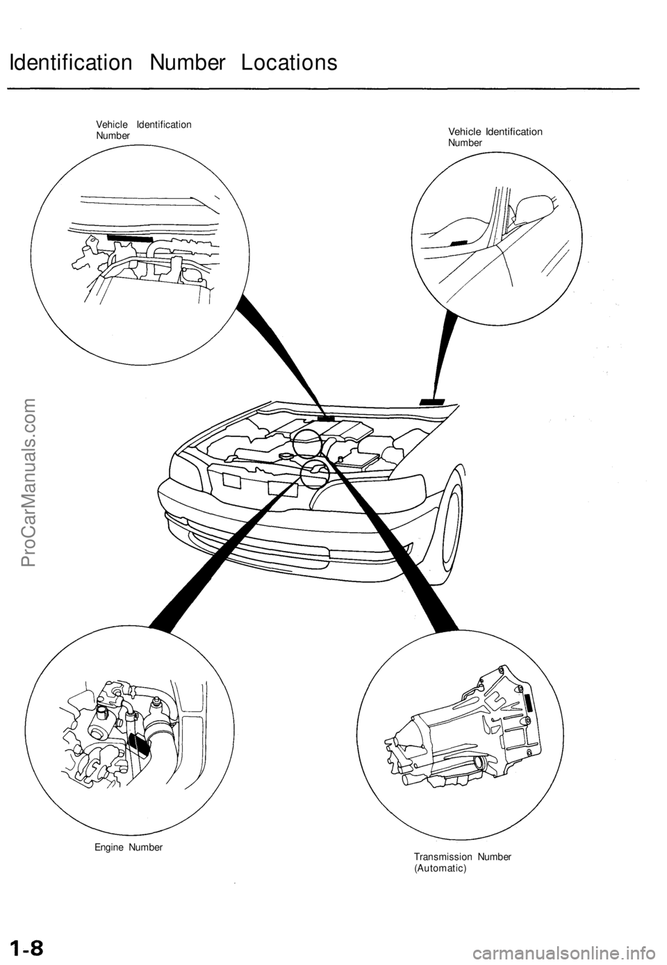
Identification Number Locations
Vehicle Identification
Number
Vehicle Identification
Number
Engine Number
Transmission Number
(Automatic)ProCarManuals.com
Page 28 of 1771
Lubrication Points
For the details of lubrication points and types of lubricants to be applied, refer to the illustrated index and various work
procedures (such as Assembly/Reassembly, Replacement, Overhaul, Installation, etc.) contained in each section.
No.
1
2
3
4
5
6
7
8
9
10
11
12
13
14
15
16
17
18
19
20
21
LUBRICATION POINTS
Engine
Transmission
Brake Line (Includes Anti-lock brake line)
Power steering gearbox
Steering boots
Throttle cable end
Steering ball joints
Shift lever (Automatic transmission)
Pedal linkage
Intermediate shaft
Brake master cylinder pushrod
Fuel
fill
lid
Trunk hinges
Door hinges upper and lower
Door opening detents
Hood hinges and hood latch
Brake pipe joint (Front and rear wheel house)
Caliper Piston seal, Dust seal,
Caliper pin, Piston
Power steering system
Differential
A/C compressor
LUBRICANT
API Service Grade: Use SH "Energy Conserving II" or SJ
"Energy Conserving" grade oil.
The oil container may also display the API Certification
mark shown below. Make sure it says "For Gasoline
Engines."
SAE Viscosity: See chart below.
Genuine Honda Premium Formula Automatic
Transmission Fluid (ATF)*1
Genuine Honda DOT3 Brake Fluid*2
Steering grease P/N 08733 - B070E
Multi-purpose grease
Honda White Lithium Grease
Rust preventives
Silicone grease
Genuine Honda Power Steering Fluid-V or S*3
Hypoid gear Oil API service GL4 or GL5
Viscosity:
at above -18°C (0°F): SAE 90
at less than -18°C (0°F): SAE 80 W-90
Compressor oil:
DENSO: ND-OIL8 (P/N 38897 - PR7 - A01 AH or 38899 -
PR7-A01)
(For Refrigerant: HFC-134a (R-134a))
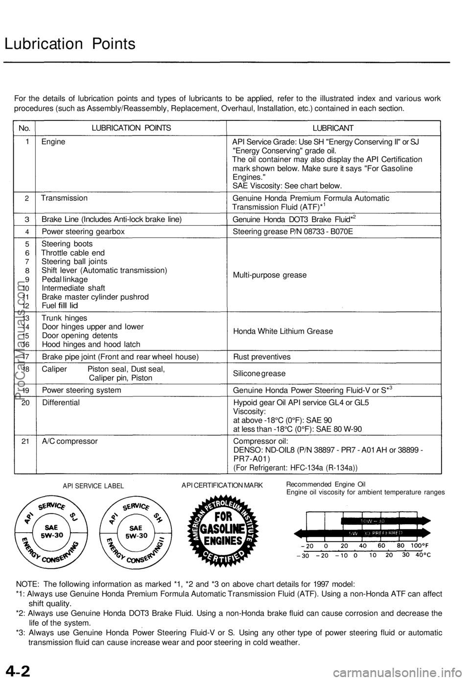
API SERVICE LABEL
API CERTIFICATION MARK
Recommended Engine Oil
Engine oil viscosity for ambient temperature ranges
NOTE: The following information as marked *1, *2 and *3 on above chart details for 1997 model:
*1: Always use Genuine Honda Premium Formula Automatic Transmission Fluid (ATF). Using a non-Honda ATF can affect
shift quality.
*2: Always use Genuine Honda DOT3 Brake Fluid. Using a non-Honda brake fluid can cause corrosion and decrease the
life of the system.
*3: Always use Genuine Honda Power Steering Fluid-V or S. Using any other type of power steering fluid or automatic
transmission fluid can cause increase wear and poor steering in cold weather.ProCarManuals.com
Page 257 of 1771
Description
The automatic transmission is a combination of a 3-element torque converter and a dual-shaft electronically controlled
automatic transmission which provides 4 speeds forward and 1 reverse. The entire unit is positioned in line with the engine.
Torque Converter, Gears and Clutches
The torque converter consists of a pump, turbine, and stator, assembled in a single unit. They are connected to the engine
crankshaft so they turn together as a unit as the engine turns. Around the outside of the drive plate is a ring gear which
meshes with the starter pinion when the engine is being started.
The entire torque converter assembly serves as a flywheel while transmitting power to the transmission mainshaft.
The transmission has two parallel shafts: the mainshaft and the countershaft. The mainshaft is in line with the engine
crankshaft. The mainshaft includes the 1st, 4th and 2nd clutches and gears for 4th, 1st, 2nd and reverse (3rd gear is integral
with the mainshaft). The countershaft includes the 3rd, 1st-hold and reverse clutches, and gears for 3rd, 4th, 1st, 2nd,
reverse and parking. The secondary drive gear is integrated with the countershaft. The gears on the mainshaft are in con-
stant mesh with those on the countershaft. When certain combinations of gears in the transmission are engaged by clutch-
positions.
and
es, power is transmitted from the mainshaft to the countershaft to provide
Electronic Control
The electronic control system consists of a Powertrain Control Module (PCM), sensors, a linear solenoid and four solenoid
valves. Shifting and lock-up are electronically controlled for comfortable driving under all conditions.
The PCM is located below the dashboard, under the front lower panel on the passenger's side.
Hydraulic Control
The lower valve body assembly includes the main valve body, the secondary valve body, the throttle valve body, the lin-
ear solenoid, the shift control solenoid valves and the ATF passage body. They are bolted on the lower part of the trans-
mission housing. The regulator valve body, the ATF pump body, and the accumulator body are bolted to the torque con-
verter housing.
The main valve body on '96 model contains the manual valve, the 1-2 shift valve, the 2-3 shift valve, the 3-4 shift valve, the
4-3 kick-down valve and the Clutch Pressure Control (CPC) valve. The main valve body on '97 model contains the manual
valve, the 1-2 shift valve, the 2-3 shift valve, the 3-4 shift valve, the 4-3 kick-down valve and the main orifice control valve.
The secondary valve body on '96 model contains the 3-4 orifice control valve, the 4-3 shift timing valve, the modulator valve
and the accumulator pistons.The secondary valve body on '97 model contains the 3-4 orifice control valve, the 4-3 shift tim-
ing valve, the line pressure control valve, the modulator valve and the accumulator pistons. The throttle valve body
includes the throttle valve which is bolted onto the secondary valve body. The linear solenoid is joined to the throttle valve
body. The regulator valve body contains the regulator valve, the lock-up shift valve and the cooler relief valve. Fluid from
the regulator passes through the manual valve to the various control valves. The ATF pump body contains the lock-up tim-
ing valve, the lock-up control valve and the relief valve. The torque converter check valve is located in the torque converter
housing under the ATF pump body. The accumulator body contains the accumulator pistons. The reverse accumulator and
the 1st-hold accumulator pistons are assembled in the rear cover.
The 1st, 1st-hold, 2nd and reverse clutches receive fluid from their respective feed pipes, and the 3rd and 4th clutches
receive fluid from the internal hydraulic circuit.
Shift Control Mechanism
Input from various sensors located throughout the vehicle determines which shift control solenoid valve the PCM will acti-
vate. Activating a shift control solenoid valve changes modulator pressure, causing a shift valve to move. This pressurizes a
line to one of the clutches, engaging the clutch and its corresponding gear.
er through a fluid passage, causing the lock-up piston to be held against the torque converter cover. As this takes place, the
mainshaft rotates at the same speed as the engine crankshaft. Together with hydraulic control, the PCM optimizes the tim-
ing of the lock-up mechanism. The lock-up valves control the range of lock-up according to lock-up control solenoid valves
A and B, and throttle valve. When lock-up control solenoid valves A and B activate, modulator pressure changes. The lock-
up control solenoid valves A and B are mounted on the torque converter housing, and are controlled by the PCM.
(cont'd)
Lock-up Mechanism
In
position, in 2nd, 3rd, and 4th, and
position in 3rd, pressurized fluid is drained from the back of the torque convert-ProCarManuals.com
Page 260 of 1771
Description
Clutches
The four-speed automatic transmission uses hydraulically-actuated clutches to engage or disengage the transmission gears.
When the hydraulic pressure is introduced into the clutch drum, the clutch piston moves. This presses the friction discs
and steel plates together, locking them so they don't slip. Power is then transmitted through the engaged clutch pack to its
hub-mounted gear.
Likewise, when the hydraulic pressure is bled from the clutch pack, the piston releases the friction discs and steel plates, and
they are free to slide past each. This allows the gear to spin independently of its shaft, transmitting no power.
1st Clutch
The 1st clutch, engages/disengages 1st gear, and is located at the middle of the mainshaft. The 1st clutch is joined back-to-
back to the 4th clutch. The 1st clutch is supplied hydraulic pressure by its ATF feed pipe within the mainshaft.
shaft. The 1st-hold clutch is supplied hydraulic pressure by its ATF feed pipe within the countershaft.
1st-hold Clutch
The 1st-hold clutch engages/disengages 1st-hold,
position or
position, and is located at the middle of the counter-
2nd Clutch
The 2nd clutch engages/disengages 2nd gear, and is located on the rear end of the mainshaft. The 2nd clutch is supplied
hydraulic pressure by its ATF feed pipe within the mainshaft.
3rd Clutch
The 3rd clutch engages/disengages 3rd gear, and is located at the end of the countershaft, opposite the rear cover. The
3rd clutch is supplied hydraulic pressure by a circuit connected to the internal hydraulic circuit.
4th Clutch
The 4th clutch engages/disengages 4th gear, and is located at the middle of the mainshaft. The 4th clutch is joined back-
to-back to the 1st clutch. The 4th clutch is supplied hydraulic pressure by a circuit connected to the internal hydraulic cir-
cuit.
Reverse Clutch
The reverse clutch engages/disengages reverse gear, and is located on the rear end of the countershaft. The reverse clutch is
supplied hydraulic pressure by its ATF feed pipe within the countershaft.
One-way Clutch
This transmission has two one-way clutches: the 1st gear one-way clutch and the 2nd gear one-way clutch. The 1st gear
one-way clutch is positioned between the countershaft 1st gear and the one-way clutch hub, with the one-way clutch hub
splined to the countershaft 2nd gear. The countershaft 1st gear provides the outer race surface, and the one-way clutch
hub provides the inner race surface. The 2nd gear one-way clutch is positioned between the countershaft 2nd gear and
the parking gear, with the parking gear splined to the countershaft. The countershaft 2nd gear provides the outer race sur-
face, and the parking gear provides the inner race surface. The one-way clutches lock up when power is transmitted from
the mainshaft 1st gear to the countershaft 1st gear. The 2nd gear one-way clutch locks up when power is transmitted from
the mainshaft 2nd gear to the countershaft 2nd gear.
The 1st clutch and gears remain engaged in the 1st, 2nd, 3rd, and 4th gear positions in the
the 1st gear one-way clutch disengages when the 2nd, 3rd, or 4th clutches/gears are applied in the
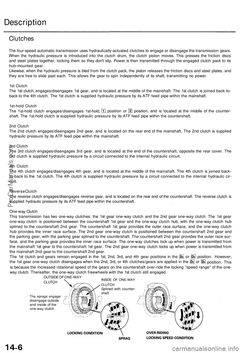
The sprags engage/
disengage outside
and inside of the
one-way clutch.
is because the increased rotational speed of the gears on the countershaft over-ride the locking "speed range" of the one-
way clutch. Thereafter, the one-way clutch freewheels with the 1st clutch still engaged.
INSIDE OF ONE-WAY
CLUTCH
Splined with counter-
shaft
OUTSIDE OF ONE-WAY
CLUTCH
position. However,
or
or
position. ThisProCarManuals.com
Page 284 of 1771
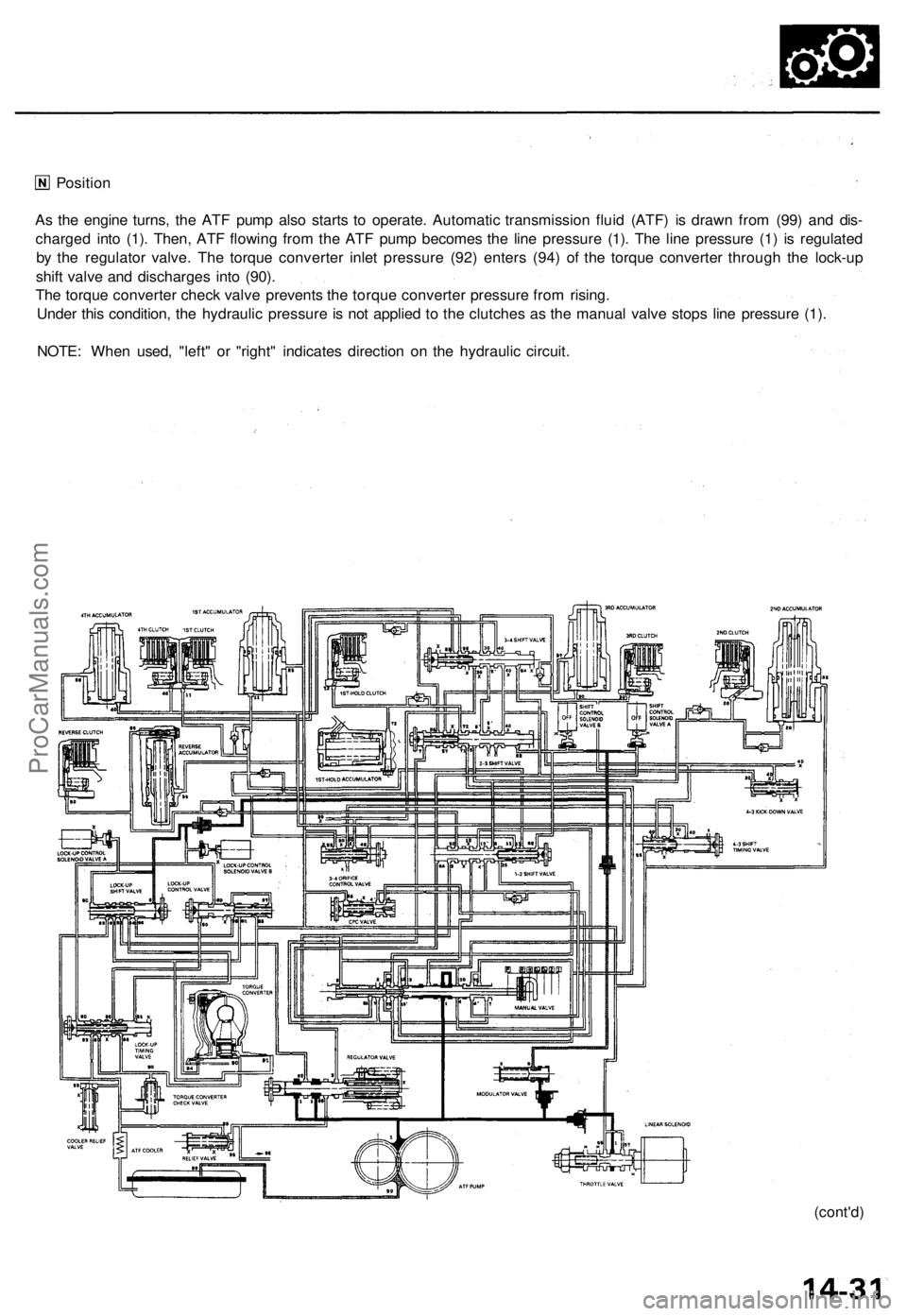
Position
(cont'd)
As the engine turns, the ATF pump also starts to operate. Automatic transmission fluid (ATF) is drawn from (99) and dis-
charged into (1). Then, ATF flowing from the ATF pump becomes the line pressure (1). The line pressure (1) is regulated
by the regulator valve. The torque converter inlet pressure (92) enters (94) of the torque converter through the lock-up
shift valve and discharges into (90).
The torque converter check valve prevents the torque converter pressure from rising.
Under this condition, the hydraulic pressure is not applied to the clutches as the manual valve stops line pressure (1).
NOTE: When used, "left" or "right" indicates direction on the hydraulic circuit.ProCarManuals.com
Page 304 of 1771
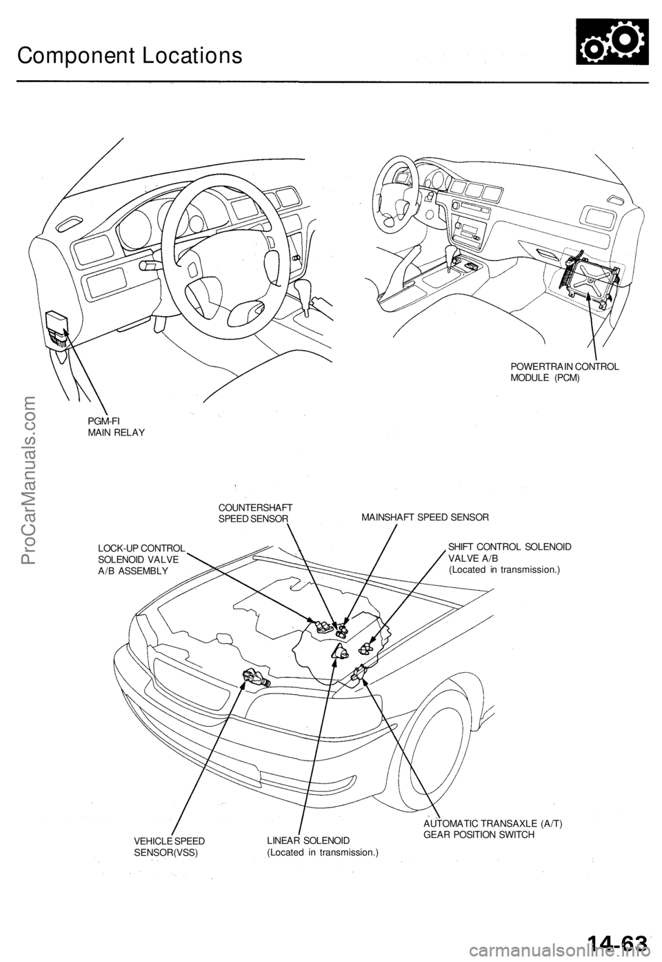
Component Locations
POWERTRAIN CONTROL
MODULE (PCM)
PGM-FI
MAIN RELAY
COUNTERSHAFT
SPEED SENSOR
MAINSHAFT SPEED SENSOR
LOCK-UP CONTROL
SOLENOID VALVE
A/B ASSEMBLY
SHIFT CONTROL SOLENOID
VALVE A/B
(Located in transmission.)
VEHICLE SPEED
SENSOR(VSS)
LINEAR SOLENOID
(Located in transmission.)
AUTOMATIC TRANSAXLE (A/T)
GEAR POSITION SWITCHProCarManuals.com
Page 328 of 1771
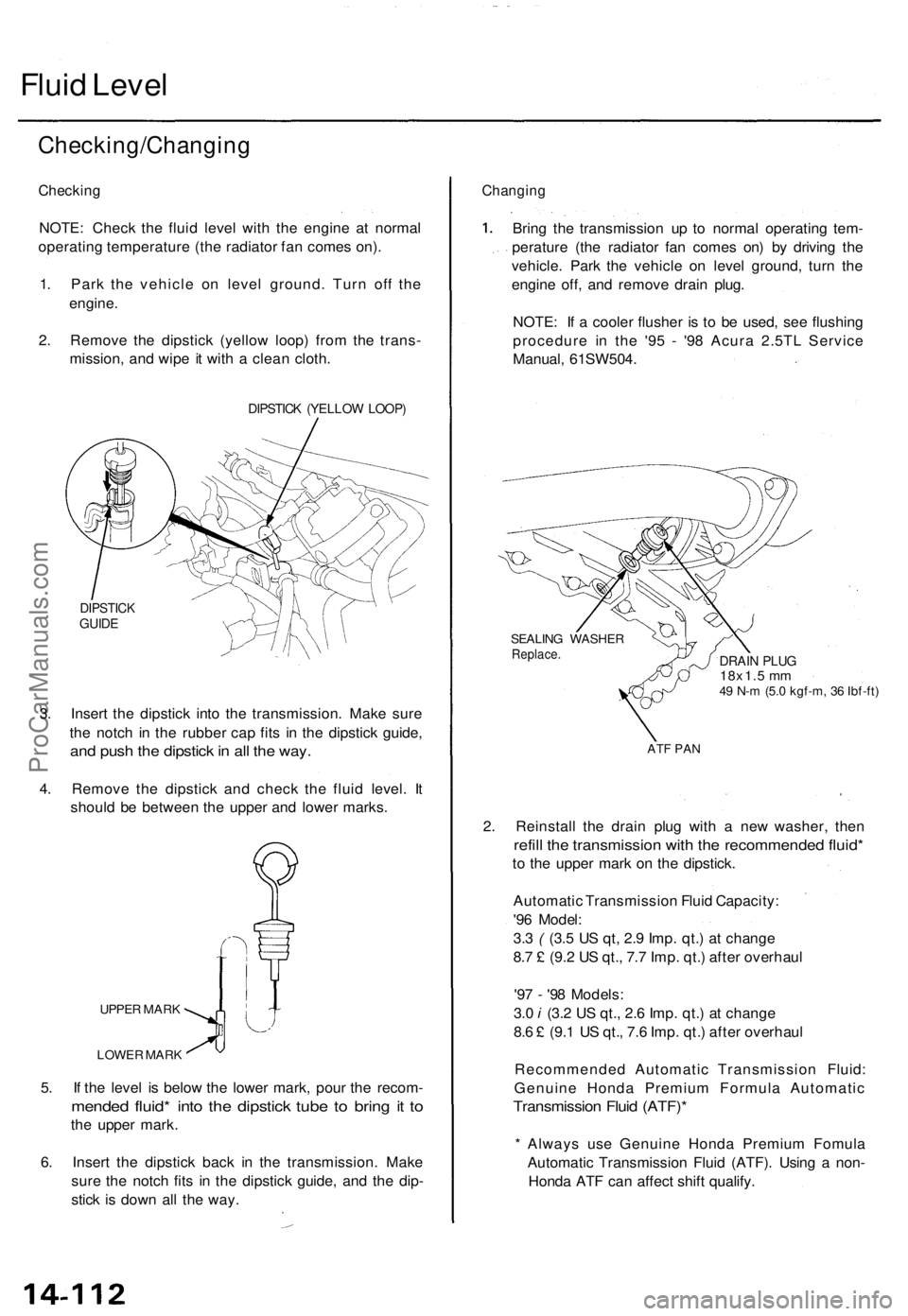
Fluid Level
Checking/Changing
Checking
NOTE: Check the fluid level with the engine at normal
operating temperature (the radiator fan comes on).
1. Park the vehicle on level ground. Turn off the
engine.
2. Remove the dipstick (yellow loop) from the trans-
mission, and wipe it with a clean cloth.
DIPSTICK (YELLOW LOOP)
DIPSTICK
GUIDE
3. Insert the dipstick into the transmission. Make sure
the notch in the rubber cap fits in the dipstick guide,
and push the dipstick in all the way.
4. Remove the dipstick and check the fluid level. It
should be between the upper and lower marks.
UPPER MARK
LOWER MARK
5. If the level is below the lower mark, pour the recom-
mended fluid* into the dipstick tube to bring it to
the upper mark.
6. Insert the dipstick back in the transmission. Make
sure the notch fits in the dipstick guide, and the dip-
stick is down all the way.
Changing
Bring the transmission up to normal operating tem-
perature (the radiator fan comes on) by driving the
vehicle. Park the vehicle on level ground, turn the
engine off, and remove drain plug.
NOTE: If a cooler flusher is to be used, see flushing
procedure in the '95 - '98 Acura 2.5TL Service
Manual, 61SW504.
SEALING WASHER
Replace.
DRAIN PLUG
18x1.5 mm
49 N-m (5.0 kgf-m, 36 Ibf-ft)
ATF PAN
2. Reinstall the drain plug with a new washer, then
refill the transmission with the recommended fluid*
to the upper mark on the dipstick.
Automatic Transmission Fluid Capacity:
'96 Model:
3.3 ( (3.5 US qt, 2.9 Imp. qt.) at change
8.7 £ (9.2 US qt., 7.7 Imp. qt.) after overhaul
'97 - '98 Models:
3.0 i (3.2 US qt., 2.6 Imp. qt.) at change
8.6 £ (9.1 US qt., 7.6 Imp. qt.) after overhaul
Recommended Automatic Transmission Fluid:
Genuine Honda Premium Formula Automatic
Transmission Fluid (ATF)*
* Always use Genuine Honda Premium Fomula
Automatic Transmission Fluid (ATF). Using a non-
Honda ATF can affect shift qualify.ProCarManuals.com
Page 679 of 1771
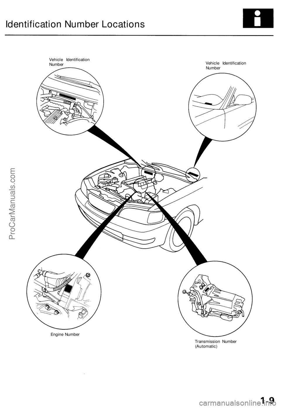
Identification Number Locations
Vehicle Identification
Number
Vehicle Identification
Number
Engine Number
Transmission Number
(Automatic)ProCarManuals.com
Page 936 of 1771
Description
The automatic transmission is a combination of a 3-element torque converter and a dual-shaft electronically controlled
automatic transmission which provides 4 speeds forward and 1 reverse. The entire unit is positioned in line with the engine.
Torque Converter, Gears and Clutches
The torque converter consists of a pump, turbine and stator, assembled in a single unit.
They are connected to the engine crankshaft so they turn together as a unit as the engine turns.
Around the outside of the drive plate is a ring gear which meshes with the starter pinion when the engine is being started.
The entire torque converter assembly serves as a flywheel while transmitting power to the transmission mainshaft.
The transmission has two parallel shafts: the mainshaft and the countershaft. The mainshaft is in line with the engine
crankshaft.
The mainshaft includes the 1st, 2nd and 4th clutches, and gears for 4th, 2nd, 1st and reverse (3rd gear is integral with the
mainshaft, while the reverse gear is integral with 4th gear).
The countershaft includes the 3rd, and 1st-hold clutches, and gears for 3rd, 4th, 1st, 2nd, reverse, and parking. The sec-
ondary drive gear is integrated with the countershaft.
The gears on the mainshaft are in constant mesh with those on the countershaft.
When certain combinations of gears in the transmission are engaged by clutches, power is transmitted from the mainshaft
to the countershaft to provide and positions.
Electronic Control
The electronic control system consists of the Transmission Control Module (TCM), sensors, a linear solenoid and four
solenoid valves. Shifting and lock-up are electronically controlled for comfortable driving under all conditions.
The TCM is located below the dashboard, behind the glove box on the passenger's side.
Hydraulic Control
The lower valve body assembly includes the main valve body, the servo body and the shift control solenoid valves. They
are bolted on the lower part of the transmission housing.
Other valve bodies, the regulator valve body, the ATF pump body, the 2nd accumulator body, and the throttle valve body,
are bolted to the torque converter housing.
The main valve body contains the manual valve, the 1 - 2 shift valve, the 2 - 3 shift valve, the 3 - 4 shift valve, the 4th kick-
down valve, the 2 - 3 orifice control valve, the 3 - 4 orifice control valve, the 4th exhaust valve, the servo control valve,
and the main orifice control valve.
The servo body contains the servo valve, 3rd and 4th accumulator pistons.
The regulator valve body contains the regulator valve, the lock-up shift valve, and the cooler relief valve.
Fluid from the regulator passes through the manual valve to the various control valves.
The throttle valve body includes the throttle valve which is bolted onto the 2nd accumulator body. The 2nd accumulator
piston is assembled in the 2nd accumulator body.
The linear solenoid is joined with the throttle valve body.
The ATF pump body contains the modulator valve, the lock-up control valve, the lock-up timing valve, and the relief valve.
The torque converter check valve is located in the torque converter housing under the ATF pump body.
The 1st and 1st-hold accumulator pistons are assembled in the rear cover.
The clutches receive fluid from their respective feed pipes or internal hydraulic circuit.
Shift Control Mechanism
Input from various sensors located throughout the vehicle determines which shift control solenoid valve the TCM will acti-
vate. Activating a shift control solenoid valve changes modulator pressure, causing a shift valve to move. This pressurizes
a line to one of the clutches, engaging that clutch and its corresponding gear.
Lock-up Mechanism
In position, in 2nd, 3rd and 4th, and in position in 3rd, pressurized fluid is drained from the back of the torque con-
verter through a fluid passage, causing the lock-up piston to be held against the torque converter cover. As this takes place,
the mainshaft rotates at the same speed as the engine crankshaft. Together with hydraulic control, the TCM optimizes the
timing of the lock-up mechanism. The lock-up valves control the range of lock-up according to lock-up control solenoid
valves A and B, and throttle valve. When lock-up control solenoid valves A and B activate, the modulator pressure changes.
The lock-up control solenoid valves A and B are mounted on the torque converter housing, and are controlled by the TCM.ProCarManuals.com
Page 954 of 1771
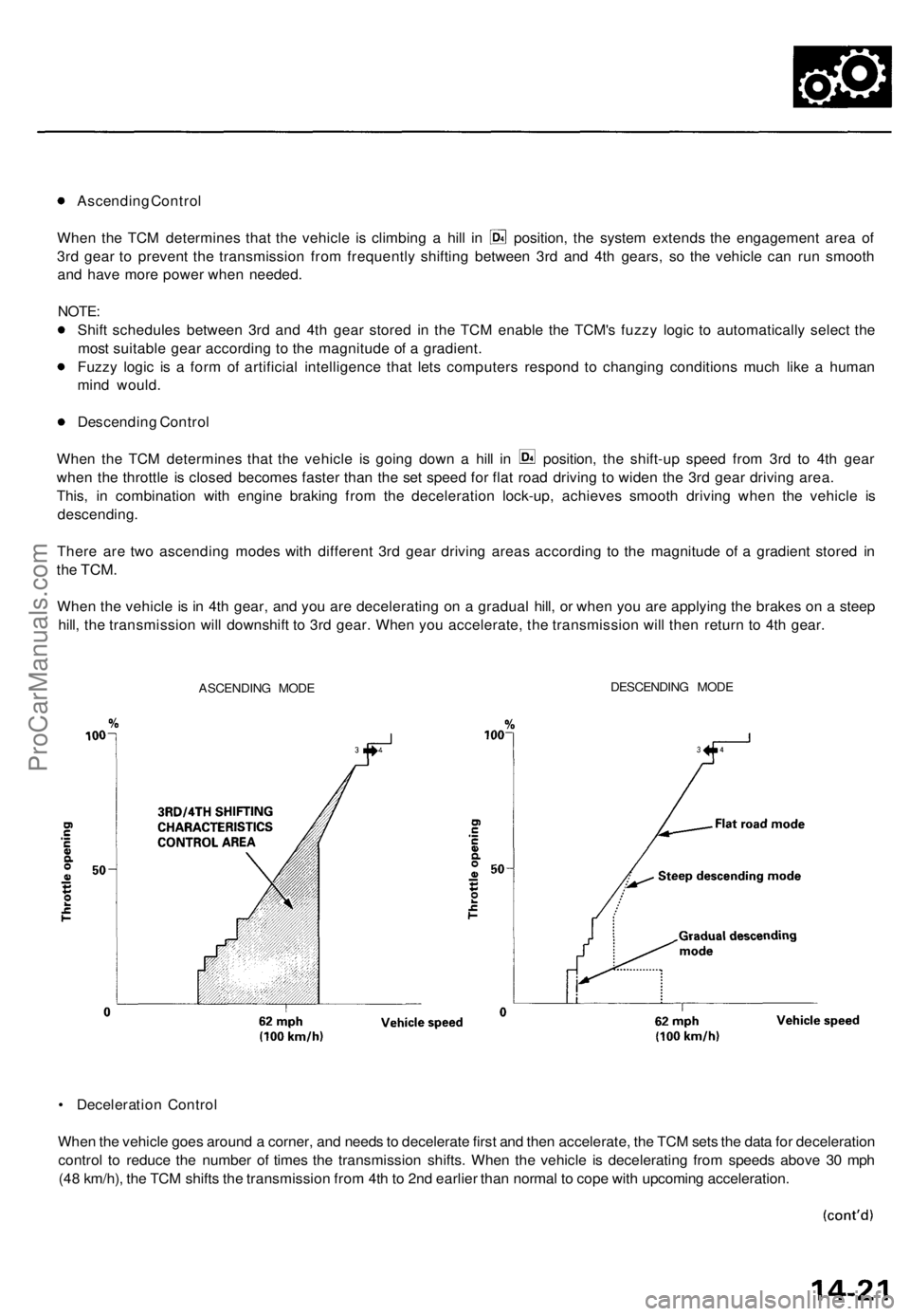
Ascending Control
When the TCM determines that the vehicle is climbing a hill in position, the system extends the engagement area of
3rd gear to prevent the transmission from frequently shifting between 3rd and 4th gears, so the vehicle can run smooth
and have more power when needed.
NOTE:
Shift schedules between 3rd and 4th gear stored in the TCM enable the TCM's fuzzy logic to automatically select the
most suitable gear according to the magnitude of a gradient.
Fuzzy logic is a form of artificial intelligence that lets computers respond to changing conditions much like a human
mind would.
Descending Control
When the TCM determines that the vehicle is going down a hill in position, the shift-up speed from 3rd to 4th gear
when the throttle is closed becomes faster than the set speed for flat road driving to widen the 3rd gear driving area.
This, in combination with engine braking from the deceleration lock-up, achieves smooth driving when the vehicle is
descending.
There are two ascending modes with different 3rd gear driving areas according to the magnitude of a gradient stored in
the
TCM.
When the vehicle is in 4th gear, and you are decelerating on a gradual hill, or when you are applying the brakes on a steep
hill, the transmission will downshift to 3rd gear. When you accelerate, the transmission will then return to 4th gear.
ASCENDING MODE
DESCENDING MODE
• Deceleration Control
When the vehicle goes around a corner, and needs to decelerate first and then accelerate, the TCM sets the data for deceleration
control to reduce the number of times the transmission shifts. When the vehicle is decelerating from speeds above 30 mph
(48 km/h), the TCM shifts the transmission from 4th to 2nd earlier than normal to cope with upcoming acceleration.ProCarManuals.com