height ACURA TL 1995 Service Repair Manual
[x] Cancel search | Manufacturer: ACURA, Model Year: 1995, Model line: TL, Model: ACURA TL 1995Pages: 1771, PDF Size: 62.49 MB
Page 10 of 1771
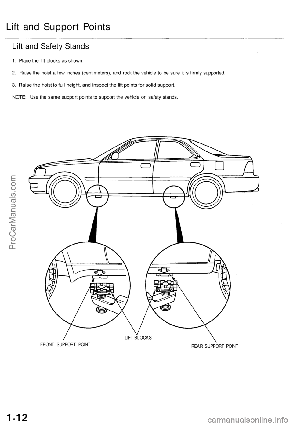
Lift and Support Points
FRONT SUPPORT POINT
REAR SUPPORT POINT
LIFT BLOCKS
Lift and Safety Stands
1. Place the lift blocks as shown.
2. Raise the hoist a few inches (centimeters), and rock the vehicle to be sure it is firmly supported.
3. Raise the hoist to full height, and inspect the lift points for solid support.
NOTE: Use the same support points to support the vehicle on safety stands.ProCarManuals.com
Page 48 of 1771
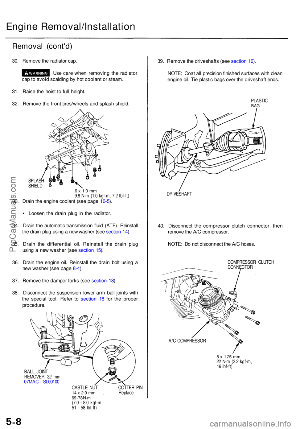
Engine Removal/Installatio n
Removal (cont'd )
30. Remov e th e radiato r cap .
Us e car e whe n removin g th e radiato r
ca p to avoi d scaldin g b y ho t coolan t o r steam .
31 . Rais e th e hois t t o ful l height .
32 . Remov e th e fron t tires/wheel s an d splas h shield .
SPLAS H
SHIEL D
6 x 1. 0 m m9.8 N- m (1. 0 kgf-m , 7. 2 Ibf-ft )33. Drai n th e engin e coolan t (se e pag e 10-5 ).
• Loose n th e drai n plu g i n th e radiator .
34 . Drai n th e automati c transmissio n flui d (ATF) . Reinstal l
th e drai n plu g usin g a ne w washe r (se e sectio n 14 ).
35 . Drai n th e differentia l oil . Reinstal l th e drai n plu g
usin g a ne w washe r (se e sectio n 15 ).
36 . Drai n th e engin e oil . Reinstal l th e drai n bol t usin g a
ne w washe r (se e pag e 8-4 ).
37 . Remov e th e dampe r fork s (se e sectio n 18 ).
38 . Disconnec t th e suspensio n lowe r ar m bal l joint s wit h
th e specia l tool . Refe r t o sectio n 1 8 fo r th e prope r
procedure .
BALL JOIN T
REMOVER , 3 2 m m
07MA C - SL0010 0
CASTLE NU T14 x 2. 0 m m69 - 7 8 N- m(7. 0 - 8. 0 kgf-m ,
5 1 - 5 8 Ibf-ft ) COTTE
R PI N
Replace .
39. Remov e th e driveshaft s (se e sectio n 16 ).
NOTE : Coa t al l precisio n finishe d surface s wit h clea n
engin e oil . Ti e plasti c bag s ove r th e driveshaf t ends .
PLASTI CBAG
DRIVESHAF T
40. Disconnec t th e compresso r clutc h connector , the n
remov e th e A/ C compressor .
NOTE : D o no t disconnec t th e A/ C hoses .
COMPRESSO R CLUTC H
CONNECTO R
A/ C COMPRESSO R
8 x 1.2 5 mm22 N- m (2. 2 kgf-m ,
1 6 Ibf-ft )
ProCarManuals.com
Page 83 of 1771
Camshaft
Inspection (cont'd)
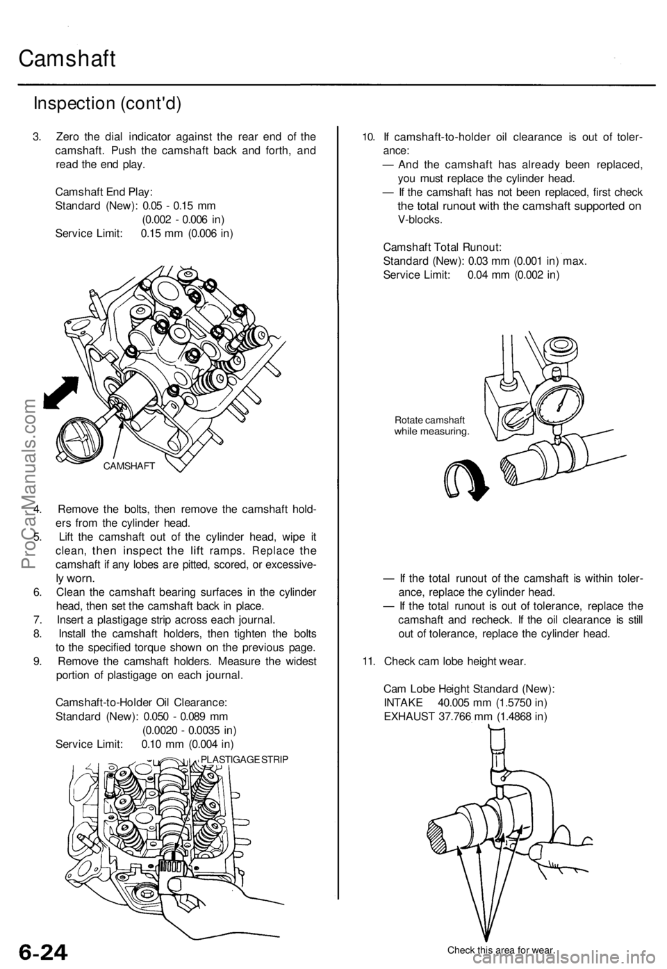
3. Zero the dial indicator against the rear end of the
camshaft. Push the camshaft back and forth, and
read the end play.
Camshaft End Play:
Standard (New): 0.05 - 0.15 mm
(0.002 - 0.006 in)
Service Limit: 0.15 mm (0.006 in)
4. Remove the bolts, then remove the camshaft hold-
ers from the cylinder head.
5. Lift the camshaft out of the cylinder head, wipe it
clean,
then
inspect
the
lift
ramps.
Replace
the
camshaft if any lobes are pitted, scored, or excessive-
ly worn.
6. Clean the camshaft bearing surfaces in the cylinder
head, then set the camshaft back in place.
7. Insert a plastigage strip across each journal.
8. Install the camshaft holders, then tighten the bolts
to the specified torque shown on the previous page.
9. Remove the camshaft holders. Measure the widest
portion of plastigage on each journal.
Camshaft-to-Holder Oil Clearance:
Standard (New): 0.050 - 0.089 mm
(0.0020 - 0.0035 in)
Service Limit: 0.10 mm (0.004 in)
PLASTIGAGE STRIP
10.
If camshaft-to-holder oil clearance is out of toler-
ance:
— And the camshaft has already been replaced,
you must replace the cylinder head.
— If the camshaft has not been replaced, first check
the total runout with the camshaft supported on
V-blocks.
Camshaft Total Runout:
Standard (New): 0.03 mm (0.001 in) max.
Service Limit: 0.04 mm (0.002 in)
Rotate camshaft
while measuring.
— If the total runout of the camshaft is within toler-
ance, replace the cylinder head.
— If the total runout is out of tolerance, replace the
camshaft and recheck. If the oil clearance is still
out of tolerance, replace the cylinder head.
11. Check cam lobe height wear.
Cam Lobe Height Standard (New):
INTAKE 40.005 mm (1.5750 in)
EXHAUST 37.766 mm (1.4868 in)
Check this area for wear.
CAMSHAFTProCarManuals.com
Page 87 of 1771
Cylinder Head s
Warpag e
NOTE: I f camshaft-to-holde r oi l clearanc e (se e pag e
6-23) i s no t withi n specifications , th e cylinde r hea d can -
not b e resurfaced .
I f camshaft-to-holde r oi l clearanc e i s withi n specifica -
tions , chec k th e cylinde r hea d fo r warpage .
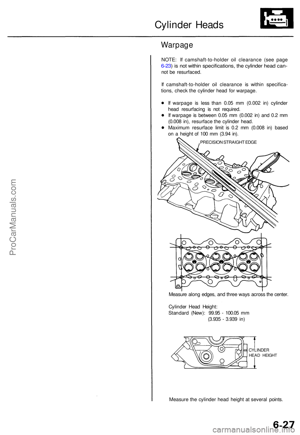
I f warpag e i s les s tha n 0.0 5 m m (0.00 2 in ) cylinde r
hea d resurfacin g i s no t required .
I f warpag e is betwee n 0.0 5 m m (0.00 2 in ) an d 0. 2 m m
(0.00 8 in) , resurfac e th e cylinde r head .
Maximu m resurfac e limi t i s 0. 2 m m (0.00 8 in ) base d
o n a heigh t o f 10 0 m m (3.9 4 in) .
PRECISIO N STRAIGH T EDG E
Measur e alon g edges , an d thre e way s acros s th e center .
Cylinde r Hea d Height :
Standar d (New) : 99.9 5 - 100.0 5 m m
(3.93 5 - 3.93 9 in )
CYLINDE RHEAD HEIGH T
Measure th e cylinde r hea d heigh t a t severa l points .
ProCarManuals.com
Page 89 of 1771
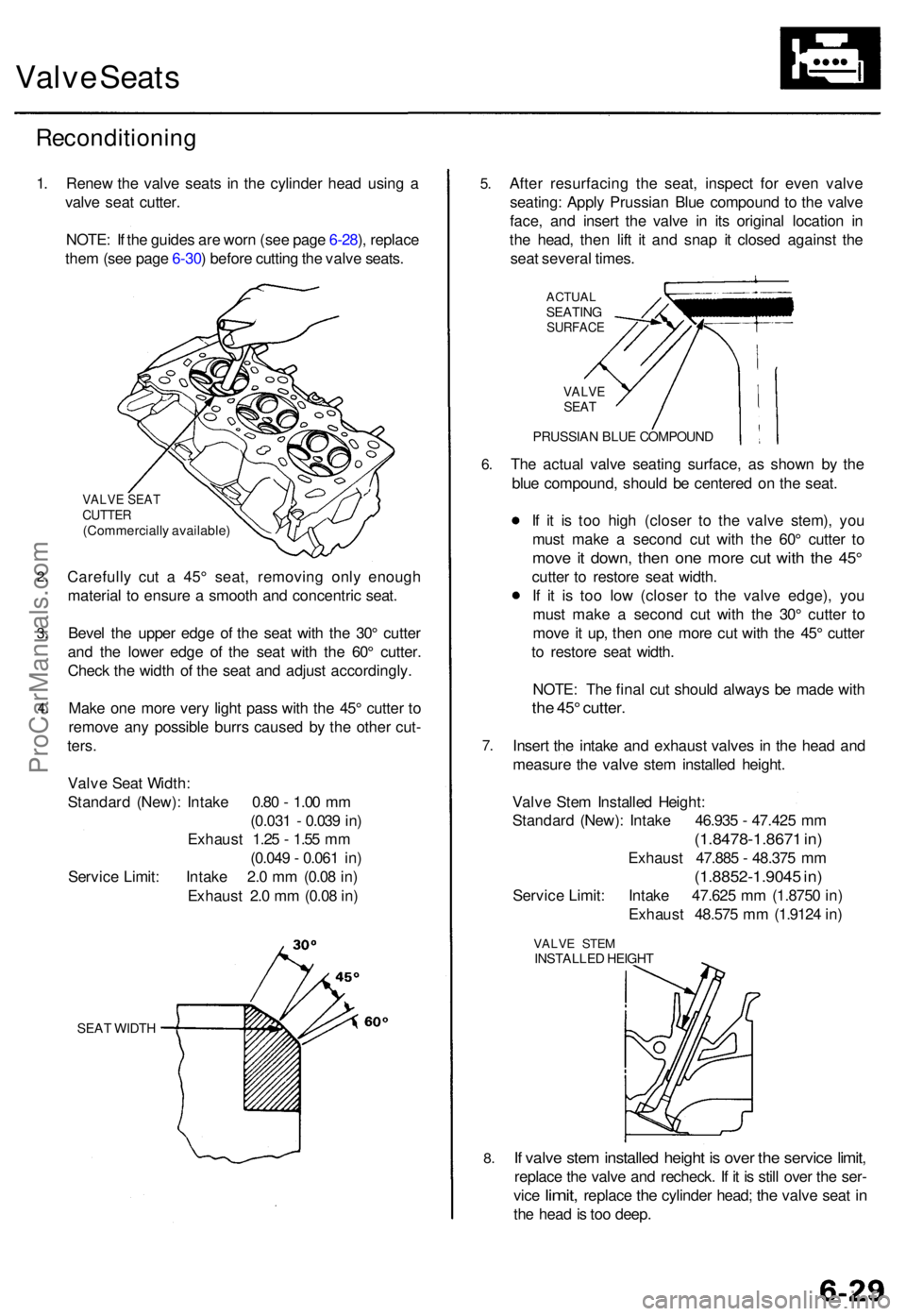
Valve Seat s
Reconditionin g
1. Rene w th e valv e seat s i n th e cylinde r hea d usin g a
valv e sea t cutter .
NOTE : I f th e guide s ar e wor n (se e pag e 6-28 ), replac e
the m (se e pag e 6-30 ) befor e cuttin g th e valv e seats .
2.
3.
4 .
VALV E SEA TCUTTE R(Commerciall y available )
Carefully cu t a 45 ° seat , removin g onl y enoug h
materia l t o ensur e a smoot h an d concentri c seat .
Beve l th e uppe r edg e o f th e sea t wit h th e 30 ° cutte r
an d th e lowe r edg e o f th e sea t wit h th e 60 ° cutter .
Chec k th e widt h o f th e sea t an d adjus t accordingly .
Mak e on e mor e ver y ligh t pas s wit h th e 45 ° cutte r t o
remov e an y possibl e burr s cause d b y th e othe r cut -
ters .
Valv e Sea t Width :
Standar d (New) : Intak e 0.8 0 - 1.0 0 m m
(0.03 1 - 0.03 9 in )
Exhaus t 1.2 5 - 1.5 5 m m
(0.04 9 - 0.06 1 in )
Servic e Limit : Intak e 2. 0 m m (0.0 8 in )
Exhaus t 2. 0 m m (0.0 8 in )
SEA T WIDT H
5.
6.
7 .
8.
Afte r resurfacin g th e seat , inspec t fo r eve n valv e
seating : Appl y Prussia n Blu e compoun d t o th e valv e
face , an d inser t th e valv e i n it s origina l locatio n i n
th e head , the n lif t i t an d sna p i t close d agains t th e
sea t severa l times .
ACTUA LSEATIN GSURFAC E
VALVESEAT
PRUSSIA N BLU E COMPOUN D
The actua l valv e seatin g surface , a s show n b y th e
blu e compound , shoul d b e centere d o n th e seat .
I f i t i s to o hig h (close r t o th e valv e stem) , yo u
mus t mak e a secon d cu t wit h th e 60 ° cutte r t o
mov e i t down , the n on e mor e cu t wit h th e 45 °
cutte r t o restor e sea t width .
I f i t i s to o lo w (close r t o th e valv e edge) , yo u
mus t mak e a secon d cu t wit h th e 30 ° cutte r t o
mov e it up , the n on e mor e cu t wit h th e 45 ° cutte r
t o restor e sea t width .
NOTE : Th e fina l cu t shoul d alway s b e mad e wit h
the 45 ° cutter .
Insert th e intak e an d exhaus t valve s i n th e hea d an d
measur e th e valv e ste m installe d height .
Valv e Ste m Installe d Height :
Standar d (New) : Intak e 46.93 5 - 47.42 5 m m
(1.8478-1.867 1 in )
Exhaus t 47.88 5 - 48.37 5 m m
(1.8852-1.904 5 in )
Servic e Limit : Intak e 47.62 5 m m (1.875 0 in )
Exhaus t 48.57 5 m m (1.912 4 in )
VALV E STE MINSTALLE D HEIGH T
If valv e ste m installe d heigh t i s ove r th e servic e limit ,
replac e th e valv e an d recheck . I f i t i s stil l ove r th e ser -
vic e
limit , replac e the cylinde r head ; the valv e sea t in
th e hea d is to o deep .
ProCarManuals.com
Page 91 of 1771
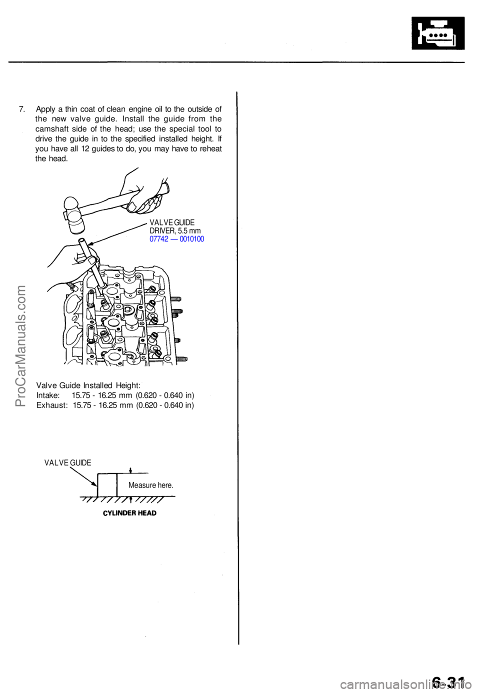
7. Appl y a thi n coa t o f clea n engin e oi l t o th e outsid e o f
th e ne w valv e guide . Instal l th e guid e fro m th e
camshaf t sid e o f th e head ; us e th e specia l too l t o
driv e th e guid e i n t o th e specifie d installe d height . I f
yo u hav e al l 1 2 guide s to do , yo u ma y hav e to rehea t
th e head .
VALV E GUID E
DRIVER , 5. 5 m m
0774 2 — 001010 0
Valve Guid e Installe d Height :
Intake : 15.7 5 - 16.2 5 m m (0.62 0 - 0.64 0 in )
Exhaust : 15.7 5 - 16.2 5 m m (0.62 0 - 0.64 0 in )
VALV E GUID E
Measure here .
ProCarManuals.com
Page 147 of 1771
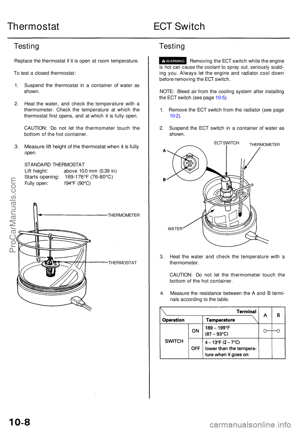
Thermostat ECT Switc h
Testin g
Replac e th e thermosta t i f i t i s ope n a t roo m temperature .
T o tes t a close d thermostat :
1 . Suspen d th e thermosta t i n a containe r o f wate r a s
shown .
2 . Hea t th e water , an d chec k th e temperatur e wit h a
thermometer . Chec k th e temperatur e a t whic h th e
thermosta t firs t opens , an d a t whic h i t i s full y open .
CAUTION : D o no t le t th e thermomete r touc h th e
botto m o f th e ho t container .
3. Measur e lif t heigh t o f th e thermosta t whe n it i s full y
open .
STANDAR D THERMOSTA T
Lif t height : abov e 10. 0 m m (0.3 9 in )
Start s opening : 169-176° F (76-80°C )
Fully open : 194° F (90°C )
THERMOMETE R
THERMOSTAT
Testing
Removin g th e EC T switc h whil e th e engin e
is ho t ca n caus e th e coolan t t o spra y out , seriousl y scald -
ing you . Alway s le t th e engin e an d radiato r coo l dow n
befor e removin g th e EC T switch .
NOTE : Blee d ai r fro m th e coolin g syste m afte r installin g
th e EC T switc h (se e pag e 10-5 ).
1 . Remov e th e EC T switc h fro m th e radiato r (se e pag e
10-2).
2 . Suspen d th e EC T switc h i n a containe r o f wate r a s
shown .
ECT SWITC HTHERMOMETE R
WATER
3. Hea t th e wate r an d chec k th e temperatur e wit h a
thermometer .
CAUTION : D o no t le t th e thermomete r touc h th e
botto m of th e ho t container .
4 . Measur e th e resistanc e betwee n th e A an d B termi -
nal s accordin g t o th e table .
ProCarManuals.com
Page 453 of 1771
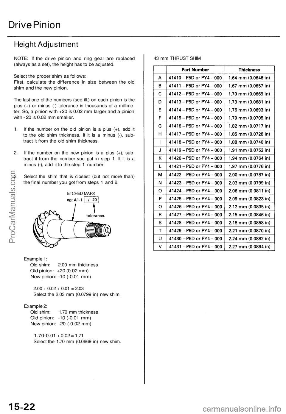
Drive Pinion
Height Adjustment
NOTE: If the drive pinion and ring gear are replaced
(always as a set), the height has to be adjusted.
Select the proper shim as follows:
First, calculate the difference in size between the old
shim and the new pinion.
The last one of the numbers (see ill.) on each pinion is the
plus (+) or minus (-) tolerance in thousands of a millime-
ter. So, a pinion with +20 is 0.02 mm larger and a pinion
with - 20 is 0.02 mm smaller.
1. If the number on the old pinion is a plus (+), add it
to the old shim thickness. If it is a minus (-), sub-
tract it from the old shim thickness.
2. If the number on the new pinion is a plus (+), sub-
tract it from the number you got in step 1. If it is a
minus (-), add it to the step 1 number.
3. Select the shim that is closest (but not more than)
the final number you got from steps 1 and 2.
Example 1:
Old shim: 2.00 mm thickness
Old pinion: +20 (0.02 mm)
New pinion: -10 (-0.01 mm)
2.00
+
0.02
+
0.01
=
2.03
Select the 2.03 mm (0.0799 in) new shim.
Example 2:
Old shim: 1.70 mm thickness
Old pinion: -10 (-0.01 mm)
New pinion: -20 (-0.02 mm)
1.70-0.01 + 0.02 = 1.71
Select the 1.70 mm (0.0669 in) new shim.
43 mm THRUST SHIM
ETCHED MARKProCarManuals.com
Page 485 of 1771
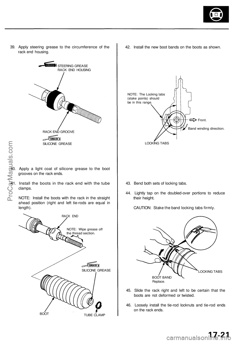
39. Appl y steerin g greas e t o th e circumferenc e o f th e
rac k en d housing .
STEERIN G GREAS E
RAC K EN D HOUSIN G
RAC K EN D GROOV E
40. Appl y a ligh t coa t o f silicon e greas e t o th e boo t
groove s o n th e rac k ends .
41. Instal l th e boot s i n th e rac k en d wit h th e tub e
clamps .
NOTE : Instal l th e boot s wit h th e rac k i n th e straigh t
ahea d positio n (righ t an d lef t tie-rod s ar e equa l i n
length) .
NOTE: Wip e greas e of fthe threa d section .
SILICON E GREAS E
BOO T
TUBE CLAM P
42. Instal l th e ne w boo t band s o n th e boot s a s shown .
NOTE: Th e Lockin g tab s
(stak e points ) shoul d
b e i n thi s range .
LOCKIN G TAB S
43. Ben d bot h set s o f lockin g tabs .
44 . Lightl y ta p o n th e doubled-ove r portion s t o reduc e
their height .
CAUTION : Stak e th e ban d lockin g tab s firmly .
LOCKIN G TAB S
BOO T BAN D
Replace .
45. Slid e th e rac k righ t an d lef t t o b e certai n tha t th e
boot s ar e no t deforme d o r twisted .
46 . Loosel y instal l th e tie-ro d locknut s an d tie-ro d end s
o n th e rac k ends .
SILICON E GREAS E
Band windin g direction .
Front.
RACK EN D
ProCarManuals.com
Page 551 of 1771
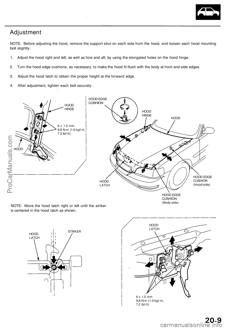
Adjustment
NOTE: Before adjusting the hood, remove the support strut on each side from the hood, and loosen each hood mounting
bolt slightly.
1. Adjust the hood right and left, as well as fore and aft, by using the elongated holes on the hood hinge.
2. Turn the hood edge cushions, as necessary, to make the hood fit flush with the body at front and side edges.
3. Adjust the hood latch to obtain the proper height at the forward edge.
4. After adjustment, tighten each bolt securely.
HOOD
HINGE
6 x 1.0 mm
9.8 N-m (1.0 kgf-m,
7.2 Ibf-ft)
HOOD
HOOD EDGE
CUSHION
HOOD
LATCH
NOTE: Move the hood latch right or left until the striker
is centered in the hood latch as shown.
HOOD
LATCH
STRIKER
HOOD EDGE
CUSHION
(Hood side)
HOOD EDGE
CUSHION
(Body side)
6 x 1.0 mm
9.8 N-m (1.0 kgf-m,
7.2 Ibf-ft)
HOOD
LATCH
HOOD
HOOD
HINGEProCarManuals.com