battery ACURA TL 1995 Service Repair Manual
[x] Cancel search | Manufacturer: ACURA, Model Year: 1995, Model line: TL, Model: ACURA TL 1995Pages: 1771, PDF Size: 62.49 MB
Page 45 of 1771
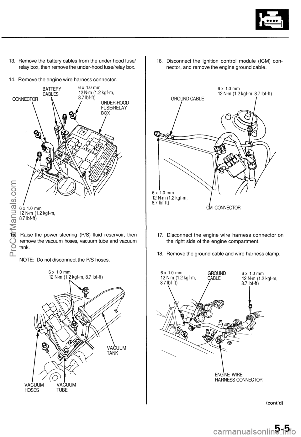
13. Remove the battery cables from the under hood fuse/
relay box, then remove the under-hood fuse/relay box.
14. Remove the engine wire harness connector.
BATTERY
CABLES
CONNECTOR
6 x 1.0 mm
12 N-m (1.2 kgf-m,
8.7 Ibf-ft)
UNDER-HOOD
FUSE/RELAY
BOX
6 x 1.0 mm
12 N-m (1.2 kgf-m,
8.7 Ibf-ft)
15. Raise the power steering (P/S) fluid reservoir, then
remove the vacuum hoses, vacuum tube and vacuum
tank.
NOTE: Do not disconnect the P/S hoses.
6 x 1.0 mm
12 N-m (1.2 kgf-m, 8.7 Ibf-ft)
VACUUM
TANK
VACUUM
HOSES
VACUUM
TUBE
16. Disconnect the ignition control module (ICM) con-
nector, and remove the engine ground cable.
GROUND CABLE
6 x 1.0 mm
12 N-m (1.2 kgf-m, 8.7 Ibf-ft)
6 x 1.0 mm
12 N-m (1.2 kgf-m,
8.7 Ibf-ft)
ICM CONNECTOR
17. Disconnect the engine wire harness connector on
the right side of the engine compartment.
18. Remove the ground cable and wire harness clamp.
6 x 1.0 mm
12 N-m (1.2 kgf-m,
8.7 Ibf-ft)
GROUND
CABLE
6 x 1.0 mm
12 N-m (1.2 kgf-m,
8.7 Ibf-ft)
ENGINE WIRE
HARNESS CONNECTORProCarManuals.com
Page 63 of 1771
Timing Bel t
Remova l
NOTE:
Replac e th e timin g bel t a t 105,00 0 mile s (168,00 0 km )
accordin g t o th e maintenanc e schedul e (norma l con -
ditions/sever e conditions) .
I f th e vehicl e is regularl y drive n i n on e o r mor e o f th e
followin g conditions , replac e th e timin g bel t a t 60,00 0
mile s (U.S.A. ) 100,00 0 k m (Canada) .
I n ver y hig h temperature s (ove r 110°F , 43°C )
I n ver y lo w temperature s (unde r -20°F , -29°C )
Tur n th e crankshaf t pulle y s o th e No . 1 pisto n i s a t
to p dea d cente r (TDC ) befor e removin g th e bel t (se e
pag e 6-8 ).
Inspec t th e wate r pum p befor e installin g th e timin g
bel t (se e pag e 10-10 ).
1 . Mak e sur e yo u hav e th e anti-thef t cod e fo r th e radio ,
the n writ e dow n th e frequencie s fo r th e radio' s prese t
buttons .
2. Disconnec t th e negativ e termina l fro m th e battery .
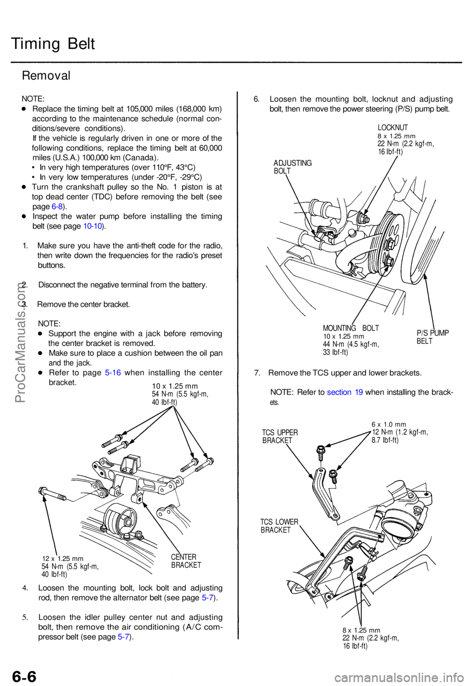
3 . Remov e th e cente r bracket .
NOTE:
Suppor t th e engin e wit h a jac k befor e removin g
th e cente r bracke t i s removed .
Mak e sur e to plac e a cushio n betwee n th e oi l pa n
and th e jack .
Refer t o pag e 5-1 6 whe n installin g th e cente r
bracket. 10 x 1.25 mm54 N- m (5. 5 kgf-m ,
4 0 Ibf-ft )
4.
5.
CENTE RBRACKE T12 x 1.2 5 mm54 N- m (5. 5 kgf-m ,
4 0 Ibf-ft )
Loose n th e mountin g bolt , loc k bol t an d adjustin g
rod , the n remov e th e alternato r bel t (se e pag e 5-7 ).
Loose n th e idle r pulle y cente r nu t an d adjustin g
bolt, the n remov e th e ai r conditionin g (A/ C com -
presso r bel t (se e pag e 5-7 ).
6 .Loose n th e mountin g bolt , locknu t an d adjustin g
bolt , the n remov e th e powe r steerin g (P/S ) pum p belt .
LOCKNU T8 x 1.2 5 mm22 N- m (2. 2 kgf-m ,
1 6 Ibf-ft )
ADJUSTIN GBOLT
MOUNTING BOL T
10 x 1.2 5 mm44 N- m (4. 5 kgf-m ,
3 3 Ibf-ft )
P/S PUM PBELT
7. Remov e th e TC S uppe r an d lowe r brackets .
NOTE : Refe r t o sectio n 1 9 whe n installin g th e brack -
ets.
TC S UPPE RBRACKE T
6 x 1. 0 m m12 N- m (1. 2 kgf-m ,
8. 7 Ibf-ft )
TC S LOWE R
BRACKE T
8 x 1.2 5 mm22 N- m (2. 2 kgf-m ,
1 6 Ibf-ft )
ProCarManuals.com
Page 73 of 1771
Cylinder Head s
Remova l
Engine remova l i s no t require d fo r thi s procedure .
Mak e sur e jack s an d safet y stand s ar e
place d properl y an d hois t bracket s ar e attache d th e t o
correc t position s o n th e engine .
CAUTION :
Us e fende r cover s t o avoi d damagin g painte d sur -
faces .
Unplu g th e wirin g connector s carefull y whil e holdin g
th e connecto r portio n to avoi d damage .
T o avoi d damagin g th e cylinde r head , wai t unti l th e
engin e coolan t temperatur e drop s belo w 100° F (38°C )
befor e loosenin g th e retainin g bolts .
NOTE :
Mark al l wirin g an d hose s t o avoi d misconnection .
Also , b e sur e tha t the y d o no t contac t othe r wirin g o r
hoses , o r interfer e wit h othe r parts .
Inspec t th e timin g bel t befor e removin g th e cylinde r
head .
Tur n th e crankshaf t pulle y s o tha t th e No . 1 pisto n i s
a t to p dea d cente r (se e pag e 6-10 ).
1 . Mak e sur e yo u hav e th e anti-thef t cod e fo r th e
radio , the n writ e dow n th e frequencie s fo r th e
radio' s prese t buttons .
2 . Disconnec t th e batter y negativ e termina l first , the n
the positiv e terminal .
3. Drai n th e engin e coolan t (se e pag e 10-5 ).
4 . Remov e th e engin e cove r (se e pag e 5-3 ).
5 . Remov e th e intak e ai r duc t an d ai r cleane r housin g
assembl y (se e pag e 5-3 ).
6 . Remov e th e throttl e cove r (se e pag e 5-4 ).
7 . Remov e th e throttl e cabl e an d cruis e contro l cabl e
b y loosenin g th e locknuts , the n sli p th e cabl e end s
ou t o f th e accelerato r linkag e (se e pag e 5-4 ).
NOTE :
Take car e no t t o ben d a cabl e whe n removin g it .
Alway s replac e an y kinke d cabl e wit h a ne w one .
Adjus t th e throttl e cabl e whe n installin g (se e
sectio n 11 ).
Adjus t th e cruis e contro l cabl e whe n installin g
(se e sectio n 23 ). 8
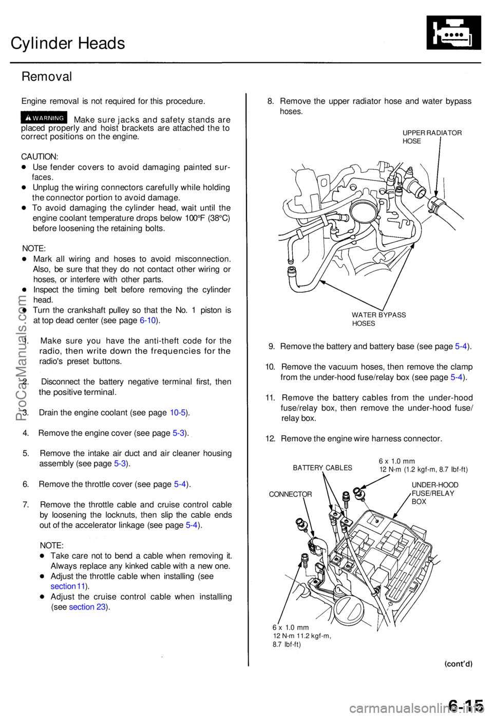
. Remov e th e uppe r radiato r hos e an d wate r bypas s
hoses.
UPPER RADIATO RHOSE
WATE R BYPAS SHOSES
9. Remov e th e batter y an d batter y bas e (se e pag e 5-4 ).
10 . Remov e th e vacuu m hoses , the n remov e th e clam p
fro m th e under-hoo d fuse/rela y bo x (se e pag e 5-4 ).
11 . Remov e th e batter y cable s fro m th e under-hoo d
fuse/rela y box , the n remov e th e under-hoo d fuse /
rela y box .
12 . Remov e th e engin e wir e harnes s connector .
BATTERY CABLE S
CONNECTO R
6 x 1. 0 m m12 N- m (1. 2 kgf-m , 8. 7 Ibf-ft )
UNDER-HOO DFUSE/RELAYBOX
6 x 1. 0 m m12 N- m 11. 2 kgf-m ,8.7 Ibf-ft )
ProCarManuals.com
Page 188 of 1771
Troubleshooting
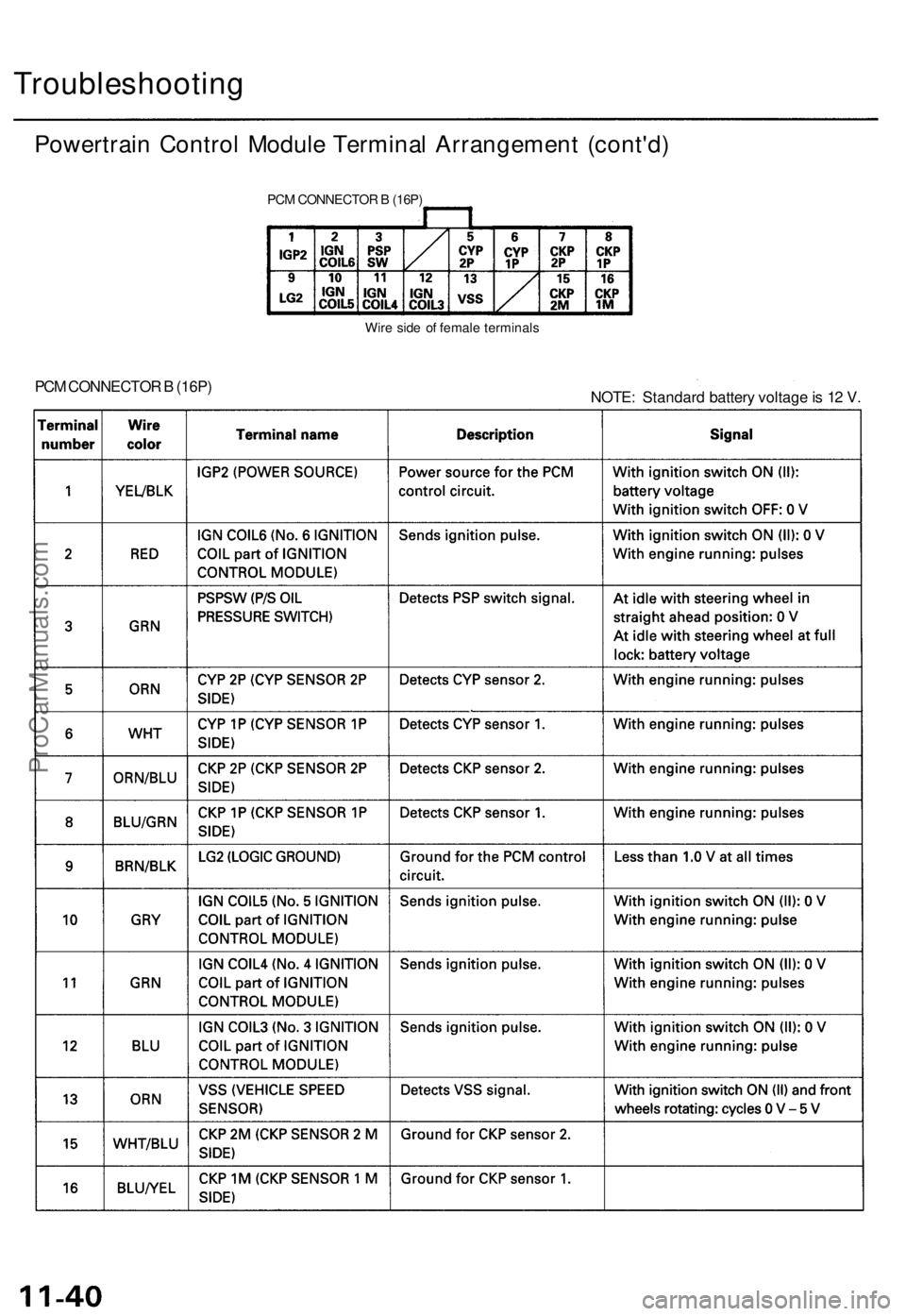
Powertrain Control Module Terminal Arrangement (cont'd)
PCM CONNECTOR B (16P)
Wire side of female terminals
PCM CONNECTOR B (16P)
NOTE: Standard battery voltage is 12 V.ProCarManuals.com
Page 190 of 1771
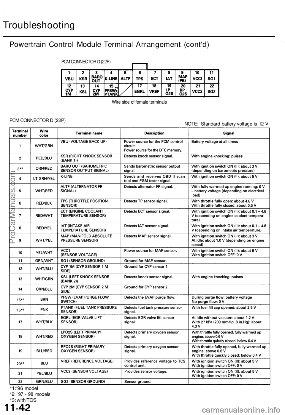
Troubleshooting
Powertrain Control Module Terminal Arrangement (cont'd)
PCM CONNECTOR D (22P)
Wire side of female terminals
PCM CONNECTOR D (22P)
NOTE: Standard battery voltage is 12 V.
*1:'96 model
*2: '97 - 98 models
*3: with TCSProCarManuals.com
Page 209 of 1771
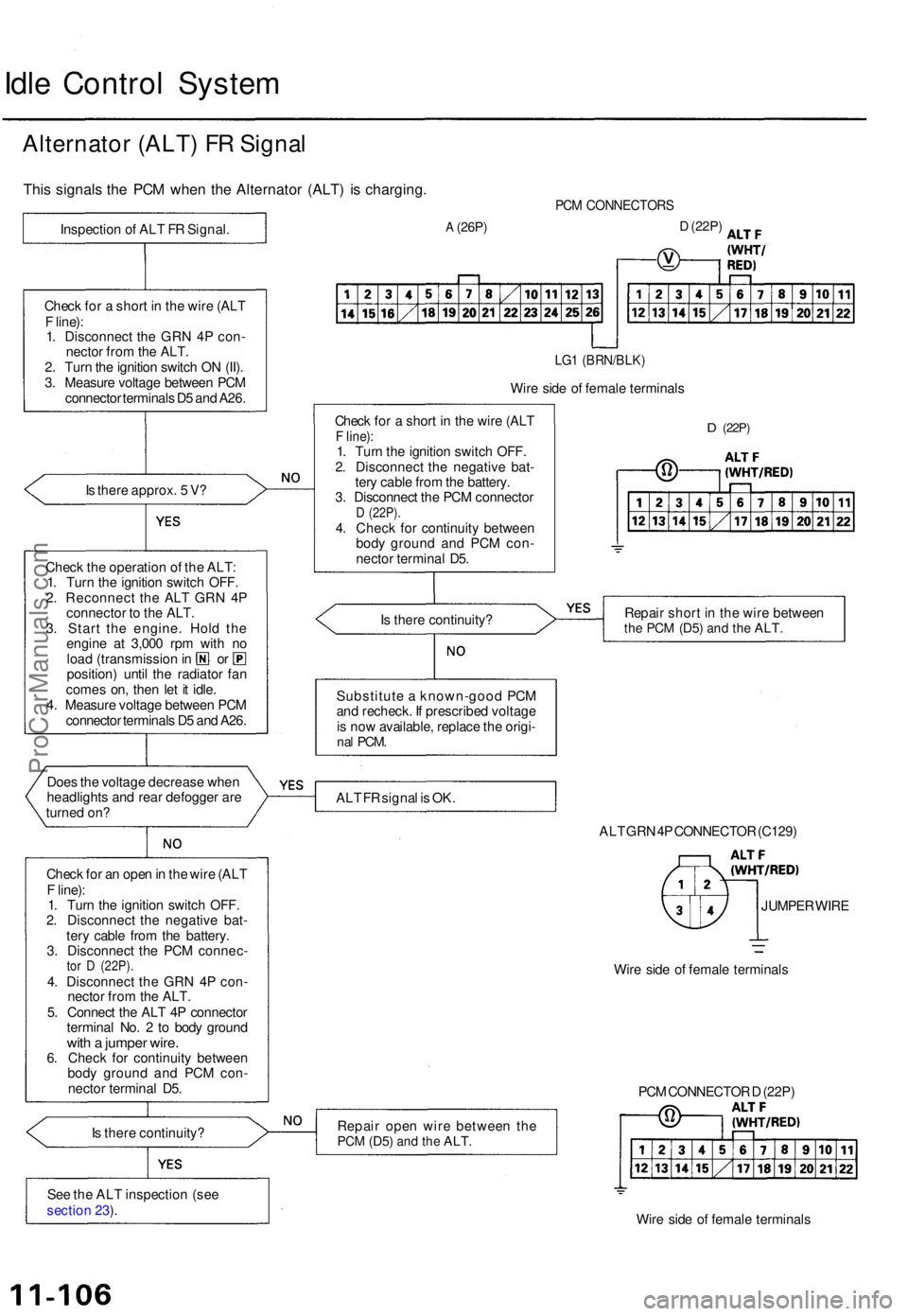
Idle Contro l Syste m
Alternato r (ALT ) F R Signa l
This signal s th e PC M whe n th e Alternato r (ALT ) i s charging .
Is ther e approx . 5 V ?
Chec k th e operatio n o f th e ALT :
1 . Tur n th e ignitio n switc h OFF .
2 . Reconnec t th e AL T GR N 4 P
connecto r t o th e ALT .
3 . Star t th e engine . Hol d th e
engin e a t 3,00 0 rp m wit h n o
loa d (transmissio n in o r
position ) unti l th e radiato r fa n
come s on , the n le t i t idle .
4 . Measur e voltag e betwee n PC M
connecto r terminal s D 5 an d A26 .
Doe s th e voltag e decreas e whe n
headlight s an d rea r defogge r ar e
turne d on ?
Chec k fo r a n ope n in th e wir e (AL T
F line) :
1 . Tur n th e ignitio n switc h OFF .
2 . Disconnec t th e negativ e bat -
ter y cabl e fro m th e battery .
3 . Disconnec t th e PC M connec -
tor D (22P) .4. Disconnec t th e GR N 4 P con -
necto r fro m th e ALT .
5 . Connec t th e AL T 4 P connecto r
termina l No . 2 to bod y groun d
with a jumpe r wire .6. Chec k fo r continuit y betwee n
bod y groun d an d PC M con -
necto r termina l D5 .
I s ther e continuity ?
Se e th e AL T inspectio n (se e
sectio n 23 ).
PC M CONNECTOR S
A (26P)D (22P )
LG1 (BRN/BLK )
Wire sid e o f femal e terminal s
Chec k fo r a shor t i n th e wir e (AL T
F line) :1. Tur n th e ignitio n switc h OFF .
2 . Disconnec t th e negativ e bat -
ter y cabl e fro m th e battery .
3 . Disconnec t th e PC M connecto r
D (22P) .4. Chec k fo r continuit y betwee n
bod y groun d an d PC M con -
necto r termina l D5 .
D (22P )
Is ther e continuity ? Repai
r shor t i n th e wir e betwee nthe PC M (D5 ) and th e ALT .
Substitut e a known-goo d PC M
an d recheck . I f prescribe d voltag e
i s no w available , replac e th e origi -
nal PCM .
ALT F R signa l i s OK .
ALT GR N 4P CONNECTO R (C129 )
JUMPE R WIR E
Wir e sid e o f femal e terminal s
Repai r ope n wir e betwee n th e
PC M (D5 ) and th e ALT .
Wire sid e o f femal e terminal s
PC
M CONNECTO R D (22P )
Chec
k fo r a shor t i n th e wir e (AL T
F line) :
1 . Disconnec t th e GR N 4 P con -
necto r fro m th e ALT .
2 . Tur n th e ignitio n switc h O N (II) .
3 . Measur e voltag e betwee n PC M
connecto r terminal s D 5 an d A26 .
Inspectio
n o f AL T F R Signal .
ProCarManuals.com
Page 210 of 1771
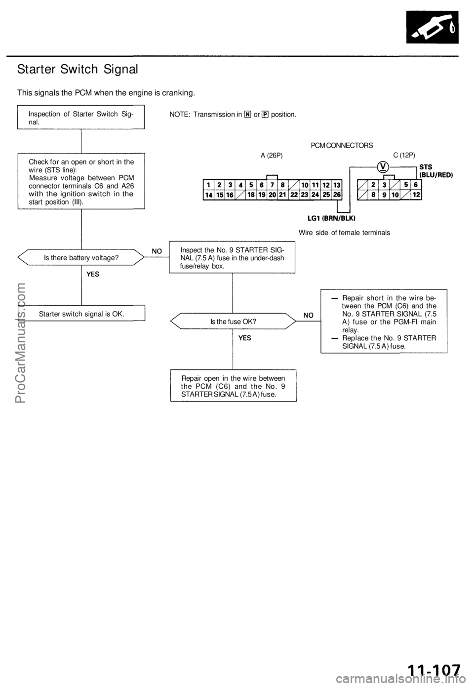
Starter Switch Signal
This signals the PCM when the engine is cranking.
PCM CONNECTORS
A
(26P)
C
(12P)
Wire side of female terminals
Is there battery voltage?
Is the fuse OK?
Repair short in the wire be-
tween the PCM (C6) and the
No. 9 STARTER SIGNAL (7.5
A) fuse or the PGM-FI main
relay.
Replace the No. 9 STARTER
SIGNAL (7.5 A) fuse.
Repair open in the wire between
the PCM
(C6)
and the No. 9
STARTER SIGNAL (7.5 A) fuse.
Starter switch signal is OK.
Inspect the No. 9 STARTER SIG-
NAL (7.5 A) fuse in the under-dash
fuse/relay box.
Check for an open or short in the
wire (STS line):
Measure voltage between PCM
connector terminals C6 and A26
with the ignition switch in the
start position (III).
Inspection of Starter Switch Sig-
nal.
NOTE: Transmission in or position.ProCarManuals.com
Page 235 of 1771
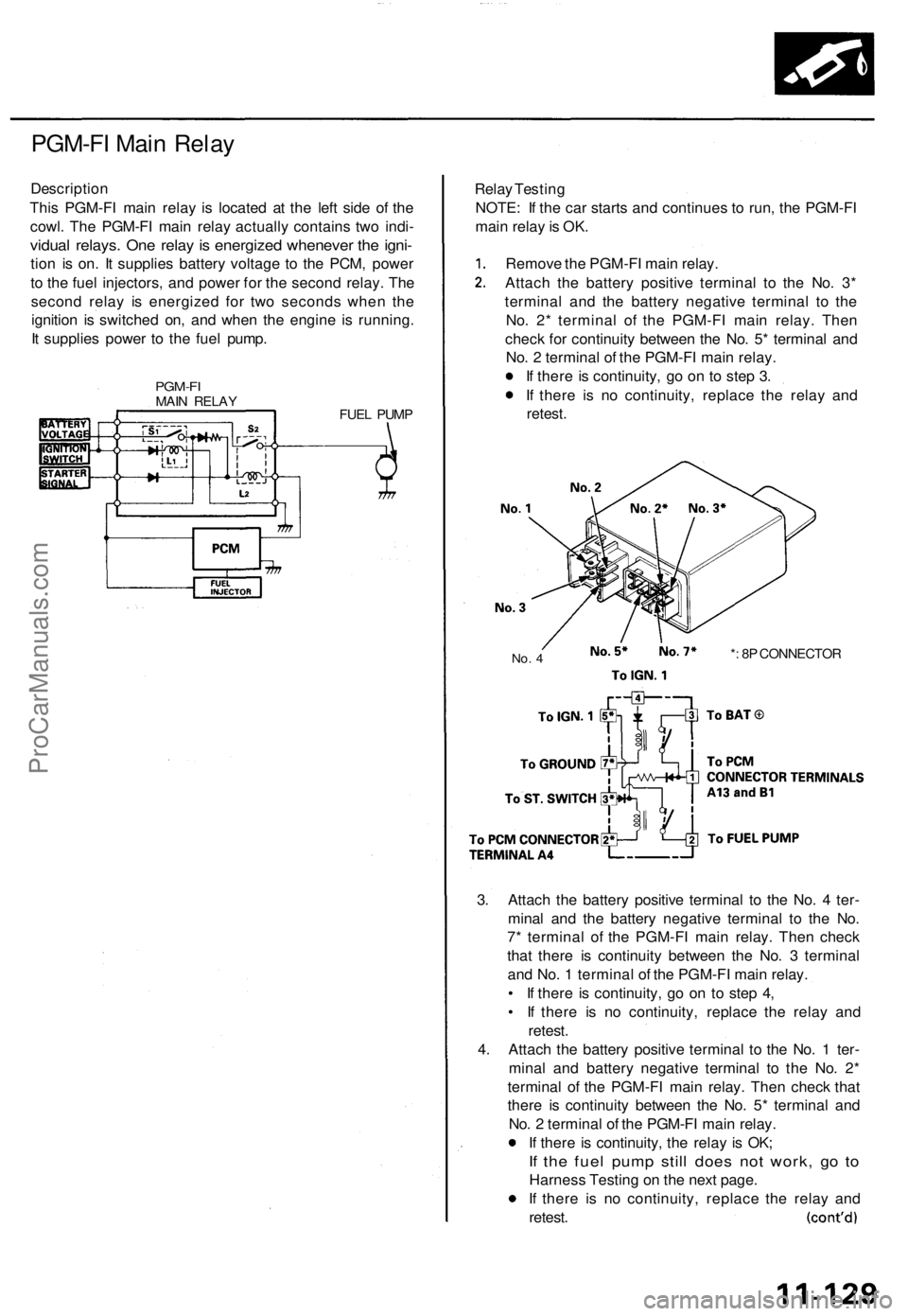
PGM-FI Main Relay
Description
This PGM-FI main relay is located at the left side of the
cowl. The PGM-FI main relay actually contains two indi-
vidual relays. One relay is energized whenever the igni-
tion is on. It supplies battery voltage to the PCM, power
to the fuel injectors, and power for the second relay. The
second relay is energized for two seconds when the
ignition is switched on, and when the engine is running.
It supplies power to the fuel pump.
PGM-FI
MAIN RELAY
FUEL PUMP
Relay Testing
NOTE: If the car starts and continues to run, the PGM-FI
main relay is OK.
Remove the PGM-FI main relay.
Attach the battery positive terminal to the No. 3*
terminal and the battery negative terminal to the
No. 2* terminal of the PGM-FI main relay. Then
check for continuity between the No. 5* terminal and
No. 2 terminal of the PGM-FI main relay.
If there is continuity, go on to step 3.
If there is no continuity, replace the relay and
retest.
No. 4
*: 8P CONNECTOR
3. Attach the battery positive terminal to the No. 4 ter-
minal and the battery negative terminal to the No.
7* terminal of the PGM-FI main relay. Then check
that there is continuity between the No. 3 terminal
and No. 1 terminal of the PGM-FI main relay.
• If there is continuity, go on to step 4,
• If there is no continuity, replace the relay and
retest.
4. Attach the battery positive terminal to the No. 1 ter-
minal and battery negative terminal to the No. 2*
terminal of the PGM-FI main relay. Then check that
there is continuity between the No. 5* terminal and
No. 2 terminal of the PGM-FI main relay.
If there is continuity, the relay is OK;
If the fuel pump still does not work, go to
Harness Testing on the next page.
If there is no continuity, replace the relay and
retest.ProCarManuals.com
Page 332 of 1771
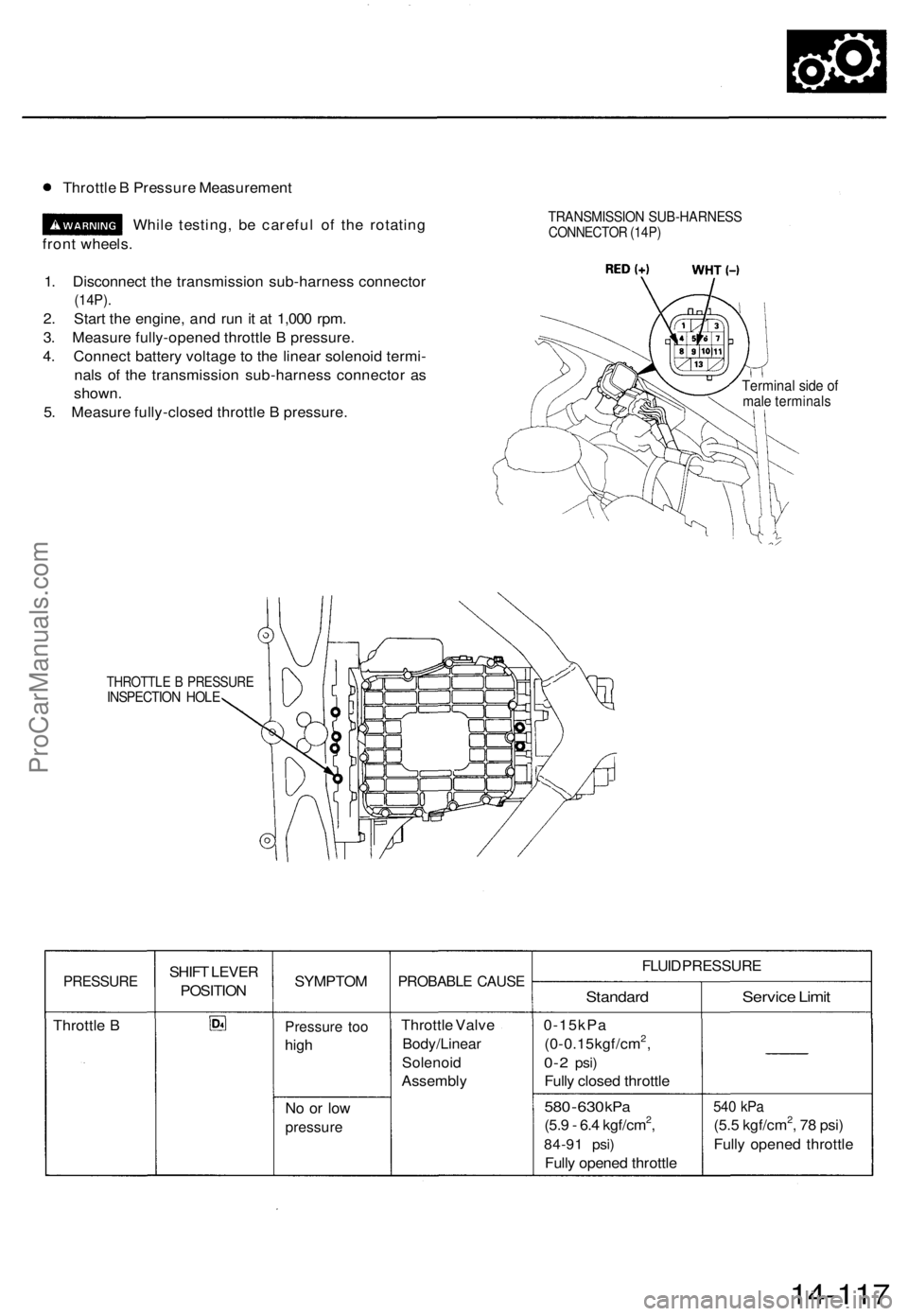
Throttle B Pressure Measurement
While testing, be careful of the rotating
front wheels.
1. Disconnect the transmission sub-harness connector
(14P).
2. Start the engine, and run it at 1,000 rpm.
3. Measure fully-opened throttle B pressure.
4. Connect battery voltage to the linear solenoid termi-
nals of the transmission sub-harness connector as
shown.
5. Measure fully-closed throttle B pressure.
TRANSMISSION SUB-HARNESS
CONNECTOR (14P)
Terminal side of
male terminals
THROTTLE B PRESSURE
INSPECTION HOLE
PRESSURE
Throttle B
SHIFT LEVER
POSITION
SYMPTOM
Pressure too
high
No or low
pressure
PROBABLE CAUSE
Throttle Valve
Body/Linear
Solenoid
Assembly
FLUID PRESSURE
Standard
0-15kPa
(0-0.15kgf/cm2,
0-2
psi)
Fully closed throttle
580
-
630
kPa
(5.9 - 6.4 kgf/cm2,
84-91 psi)
Fully opened throttle
Service Limit
540 kPa
(5.5 kgf/cm2, 78 psi)
Fully opened throttle
14-117ProCarManuals.com
Page 334 of 1771
![ACURA TL 1995 Service Repair Manual
6. Disconnect the transmission sub-harness connector (14P).
7. Start the engine, and run it at 2,000 rpm.
TRANSMISSION SUB-HARNESS
CONNECTOR (14P)
8. Shift to the [HI or [P] position, and measure ACURA TL 1995 Service Repair Manual
6. Disconnect the transmission sub-harness connector (14P).
7. Start the engine, and run it at 2,000 rpm.
TRANSMISSION SUB-HARNESS
CONNECTOR (14P)
8. Shift to the [HI or [P] position, and measure](/img/32/56993/w960_56993-333.png)
6. Disconnect the transmission sub-harness connector (14P).
7. Start the engine, and run it at 2,000 rpm.
TRANSMISSION SUB-HARNESS
CONNECTOR (14P)
8. Shift to the [HI or [P] position, and measure line pressure at fully-opened throttle.
9. Connect battery voltage to the linear solenoid terminals of the transmission sub-harness connector as shown.
10. Measure line pressure at fully-closed throttle.
If line pressure is out of specification, check and repair the probable cause in the table below.
PRESSURE
Line
SHIFT LEVER
POSITION
or
SYMPTOM
No (or
low)
line pressure
PROBABLE CAUSE
Torque converter,
ATF pump, pres-
sure regulator.
torque converter
check valve
FLUID PRESSURE
Standard
520 kPa
(5.3 kgf/cm2, 75 psi)
Fully closed throttle
|
910 kPa
(9.3 kgf/cm2, 130 psi)
Fully opened throttle
Service Limit
500 kPa
(5.1 kgf/cm2, 73 psi)
Fully closed throttle
790 kPa
(8.1 kgf/cm2, 120 psi)
Fully opened throttle
11. Stop the engine, and connect the transmission sub-harness connector (14P).
12. Disconnect the special tool from line pressure inspection hole, and connect the special tool to each inspection hole.
13. Start the engine, and run it at 2,000 rpm.
(cont'd)ProCarManuals.com