turn signal ACURA TL 1995 Service Repair Manual
[x] Cancel search | Manufacturer: ACURA, Model Year: 1995, Model line: TL, Model: ACURA TL 1995Pages: 1771, PDF Size: 62.49 MB
Page 185 of 1771
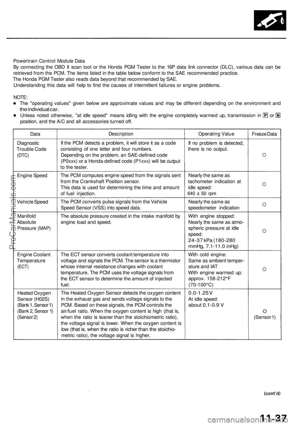
Powertrain Contro l Modul e Dat a
B y connectin g th e OB D II sca n too l o r th e Hond a PG M Teste r t o th e 16 P dat a lin k connecto r (DLC) , variou s dat a ca n b e
retrieve d fro m th e PCM . Th e item s liste d in th e tabl e belo w confor m to th e SA E recommende d practice .
Th e Hond a PG M Teste r als o read s dat a beyon d tha t recommende d b y SAE .
Understandin g thi s dat a wil l hel p t o fin d th e cause s o f intermitten t failure s o r engin e problems .
NOTE:
The "operatin g values " give n belo w ar e approximat e value s an d ma y b e differen t dependin g o n th e environmen t an d
the individua l car .
Unles s note d otherwise , "a t idl e speed " mean s idlin g wit h th e engine completel y warme d up , transmissio n i n o r
position , an d th e A/ C an d al l accessorie s turne d off .
Dat aDescriptio nOperating Valu e
Freeze Dat a
Diagnosti c
Troubl e Cod e
(DTC )
If th e PC M detect s a problem , i t wil l stor e it a s a cod e
consistin g o f on e lette r an d fou r numbers .
Dependin g o n th e problem , a n SAE-define d cod e
(P0xxx ) o r a Honda-define d cod e (P1xxx ) wil l b e outpu t
t o th e tester . I
f n o proble m is detected ,
ther e i s n o output .
Engin e Spee d Th
e PC M compute s engin e spee d fro m th e signal s sen t
fro m th e Crankshaf t Positio n sensor .
Thi s dat a is use d fo r determinin g th e tim e an d amoun t
o f fue l injection . Nearl
y th e sam e a s
tachomete r indicatio n a t
idl e speed :
640 5 0 rp m
Vehicl e Spee d Th
e PC M convert s puls e signal s fro m th e Vehicl e
Spee d Senso r (VSS ) int o spee d data . Nearl
y th e sam e a s
speedomete r indicatio n
Manifol d
Absolut e
Pressur e (MAP )
The absolut e pressur e create d in th e intak e manifol d b y
engin e loa d an d speed . Wit
h engin e stopped :
Nearl y th e sam e a s atmo -
spheri c pressur e a t idl e
speed :
24-37 kP a (180-28 0
mmHg, 7.1-11. 0 inHg )
Engin e Coolan t
Temperatur e
(ECT)
The EC T senso r convert s coolan t temperatur e int o
voltag e an d signal s th e PCM . Th e senso r i s a thermisto r
whos e interna l resistanc e change s wit h coolan t
temperature . Th e PC M use s th e voltag e signal s fro m
th e EC T senso r t o determin e th e amoun t o f injecte d
fuel . Wit
h col d engine :
Sam e a s ambien t temper -
atur e an d IA T
Wit h engin e warme d up :
approx . 158-212° F
(70-100°C )
Heate d Oxyge n
Senso r (H02S )
(Bank 1, Sensor 1)
(Ban k 2 , Senso r 1 )
(Senso r 2 )
Th e Heate d Oxyge n Senso r detect s th e oxyge n conten t
i n th e exhaus t ga s an d send s voltag e signal s to th e
PCM . Base d o n thes e signals , th e PC M control s th e
air/fue l ratio . Whe n th e oxyge n conten t i s hig h (tha t is ,
whe n th e rati o is leane r tha n th e stoichiometri c ratio) ,
th e voltag e signa l i s lower . Whe n th e oxyge n conten t i s
lo w (tha t is , whe n th e rati o is riche r tha n th e stoichio -
metric ratio) , th e voltag e signa l i s higher .
0.0-1.2 5 V
A t idl e speed :
about 0.1-0. 9 V
O
(Senso r 1 )
ProCarManuals.com
Page 199 of 1771
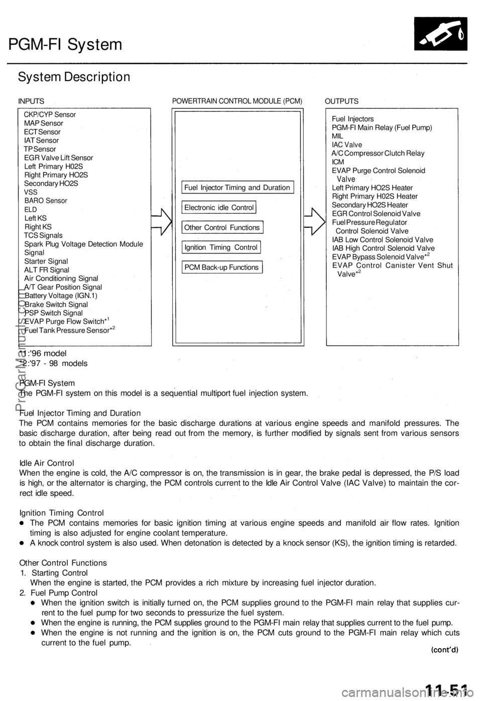
PGM-FI Syste m
System Descriptio n
INPUTS POWERTRAI N CONTRO L MODUL E (PCM ) OUTPUT S
Fue l Injector s
PGM-F I Mai n Rela y (Fue l Pump )
MILIAC Valv eA/C Compresso r Clutc h Rela yICMEVA P Purg e Contro l Solenoi dValveLeft Primar y HO2 S Heate r
Righ t Primar y H02 S Heate r
Secondar y HO2 S Heate r
EG R Contro l Solenoi d Valv e
Fue l Pressur e Regulato r
Contro l Solenoi d Valv e
IA B Lo w Contro l Solenoi d Valv e
IA B Hig h Contro l Solenoi d Valv e
EVA P Bypas s Solenoi d Valve*
2
EVA P Contro l Caniste r Ven t Shu t
Valve*2
*1:'9 6 mode l
*2:'97 - 9 8 model s
PGM-F I Syste m
Th e PGM-F I syste m o n thi s mode l i s a sequentia l multipor t fue l injectio n system .
Fue l Injecto r Timin g an d Duratio n
Th e PC M contain s memorie s fo r th e basi c discharg e duration s a t variou s engin e speed s an d manifol d pressures . Th e
basi c discharg e duration , afte r bein g rea d ou t fro m th e memory , i s furthe r modifie d b y signal s sen t fro m variou s sensor s
t o obtai n th e fina l discharg e duration .
Idl e Ai r Contro l
Whe n th e engin e is cold , th e A/ C compresso r i s on , th e transmissio n i s i n gear , th e brak e peda l i s depressed , th e P/ S loa d
i s high , o r th e alternato r i s charging , th e PC M control s curren t t o th e Idl e Ai r Contro l Valv e (IA C Valve ) t o maintai n th e cor -
rec t idl e speed .
Ignitio n Timin g Contro l
Th e PC M contain s memorie s fo r basi c ignitio n timin g a t variou s engin e speed s an d manifol d ai r flo w rates . Ignitio n
timin g i s als o adjuste d fo r engin e coolan t temperature .
A knoc k contro l syste m is als o used . Whe n detonatio n is detecte d b y a knoc k senso r (KS) , th e ignitio n timin g is retarded .
Othe r Contro l Function s
1 . Startin g Contro l
Whe n th e engin e is started , th e PC M provide s a ric h mixtur e b y increasin g fue l injecto r duration .
2 . Fue l Pum p Contro l
Whe n th e ignitio n switc h i s initiall y turne d on , th e PC M supplie s groun d t o th e PGM-F I mai n rela y tha t supplie s cur -
ren t t o th e fue l pum p fo r tw o second s t o pressuriz e th e fue l system .
Whe n th e engin e is running , th e PC M supplie s groun d to th e PGM-F I mai n rela y tha t supplie s curren t t o th e fue l pump .
Whe n th e engin e i s no t runnin g an d th e ignitio n i s on , th e PC M cut s groun d t o th e PGM-F I mai n rela y whic h cut s
curren t t o th e fue l pump .
CKP/CY P Senso rMAP Senso r
EC T Senso r
IA T Senso r
T P Senso r
EG R Valv e Lif t Senso r
Lef t Primar y H02 S
Righ t Primar y HO2 S
Secondar y HO2 S
VSSBAR O Senso rELDLef t K S
Righ t K S
TC S Signal s
Spar k Plu g Voltag e Detectio n Modul e
Signa l
Starte r Signa l
AL T F R Signa l
Air Conditionin g Signa lA/T Gea r Positio n Signa l
Batter y Voltag e (IGN.1 )
Brak e Switc h Signa l
PS P Switc h Signa l
EVA P Purg e Flo w Switch*
1
Fue l Tan k Pressur e Sensor*2
PC M Back-u p Function s
Ignitio
n Timin g Contro l
Othe
r Contro l Function s
Electroni
c idl e Contro l
Fue
l Injecto r Timin g an d Duratio n
ProCarManuals.com
Page 200 of 1771
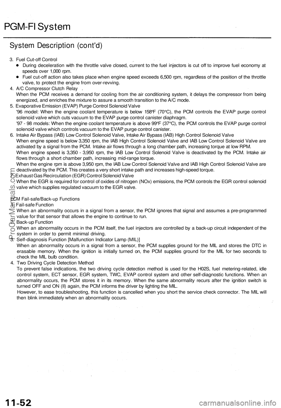
PGM-FI System
System Description (cont'd)
3. Fuel Cut-off Control
During deceleration with the throttle valve closed, current to the fuel injectors is cut off to improve fuel economy at
speeds over 1,000 rpm.
Fuel cut-off action also takes place when engine speed exceeds 6,500 rpm, regardless of the position of the throttle
valve, to protect the engine from over-revving.
4. A/C Compressor Clutch Relay .
When the PCM receives a demand for cooling from the air conditioning system, it delays the compressor from being
energized, and enriches the mixture to assure a smooth transition to the A/C mode.
5. Evaporative Emission (EVAP) Purge Control Solenoid Valve
'96 model: When the engine coolant temperature is below 158°F (70°C), the PCM controls the EVAP purge control
solenoid valve which cuts vacuum to the EVAP purge control canister diaphragm.
'97 - 98 models: When the engine coolant temperature is above 99°F (37°C), the PCM controls the EVAP purge control
solenoid valve which controls vacuum to the EVAP purge control canister.
6. Intake Air Bypass (IAB) Low Control Solenoid Valve, Intake Air Bypass (IAB) High Control Solenoid Valve
When engine speed is below 3,350 rpm, the IAB High Control Solenoid Valve and IAB Low Control Solenoid Valve are
activated by a signal from the PCM. Intake air flows through a long chamber path, increasing torque at low RPM.
When engine speed is 3,350 - 3,950 rpm, the IAB Low Control Solenoid Valve is deactivated by the PCM. Intake air
flows through a short chamber path, increasing mid-range torque.
When the engine rpm is above 3,950 rpm, the IAB Low Control Solenoid Valve and IAB High Control Solenoid Valve are
deactivated by the PCM. This creates a very short intake path and increases high-speed torque.
7. Exhaust Gas Recirculation (EGR) Control Solenoid Valve
When the EGR is required for control of oxides of nitrogen (NOx) emissions, the PCM controls the EGR control solenoid
valve which supplies regulated vacuum to the EGR valve.
ECM Fail-safe/Back-up Functions
1. Fail-safe Function
When an abnormality occurs in a signal from a sensor, the PCM ignores that signal and assumes a pre-programmed
value for that sensor that allows the engine to continue to run.
2. Back-up Function
When an abnormality occurs in the PCM itself, the fuel injectors are controlled by a back-up circuit independent of the
system in order to permit minimal driving.
3. Self-diagnosis Function [Malfunction Indicator Lamp (MIL)]
When an abnormality occurs in a signal from a sensor, the PCM supplies ground for the MIL and stores the DTC in
erasable memory. When the ignition is initially turned on, the PCM supplies ground for the MIL for two seconds to
check the MIL bulb condition.
4. Two Driving Cycle Detection Method
To prevent false indications, the two driving cycle detection method is used for the H02S, fuel metering-related, idle
control system, ECT sensor, EGR system, TWC, EVAP control system and other self-diagnostic functions. When an
abnormality occurs, the PCM stores it in its memory. When the same abnormality recurs after the ignition switch is
turned OFF and ON (II) again, the PCM informs the driver by lighting the MIL.
However, to ease troubleshooting, this function is cancelled when you short the service check connector. The MIL will
then blink immediately when an abnormality occurs.ProCarManuals.com
Page 209 of 1771
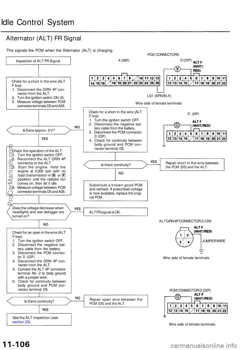
Idle Contro l Syste m
Alternato r (ALT ) F R Signa l
This signal s th e PC M whe n th e Alternato r (ALT ) i s charging .
Is ther e approx . 5 V ?
Chec k th e operatio n o f th e ALT :
1 . Tur n th e ignitio n switc h OFF .
2 . Reconnec t th e AL T GR N 4 P
connecto r t o th e ALT .
3 . Star t th e engine . Hol d th e
engin e a t 3,00 0 rp m wit h n o
loa d (transmissio n in o r
position ) unti l th e radiato r fa n
come s on , the n le t i t idle .
4 . Measur e voltag e betwee n PC M
connecto r terminal s D 5 an d A26 .
Doe s th e voltag e decreas e whe n
headlight s an d rea r defogge r ar e
turne d on ?
Chec k fo r a n ope n in th e wir e (AL T
F line) :
1 . Tur n th e ignitio n switc h OFF .
2 . Disconnec t th e negativ e bat -
ter y cabl e fro m th e battery .
3 . Disconnec t th e PC M connec -
tor D (22P) .4. Disconnec t th e GR N 4 P con -
necto r fro m th e ALT .
5 . Connec t th e AL T 4 P connecto r
termina l No . 2 to bod y groun d
with a jumpe r wire .6. Chec k fo r continuit y betwee n
bod y groun d an d PC M con -
necto r termina l D5 .
I s ther e continuity ?
Se e th e AL T inspectio n (se e
sectio n 23 ).
PC M CONNECTOR S
A (26P)D (22P )
LG1 (BRN/BLK )
Wire sid e o f femal e terminal s
Chec k fo r a shor t i n th e wir e (AL T
F line) :1. Tur n th e ignitio n switc h OFF .
2 . Disconnec t th e negativ e bat -
ter y cabl e fro m th e battery .
3 . Disconnec t th e PC M connecto r
D (22P) .4. Chec k fo r continuit y betwee n
bod y groun d an d PC M con -
necto r termina l D5 .
D (22P )
Is ther e continuity ? Repai
r shor t i n th e wir e betwee nthe PC M (D5 ) and th e ALT .
Substitut e a known-goo d PC M
an d recheck . I f prescribe d voltag e
i s no w available , replac e th e origi -
nal PCM .
ALT F R signa l i s OK .
ALT GR N 4P CONNECTO R (C129 )
JUMPE R WIR E
Wir e sid e o f femal e terminal s
Repai r ope n wir e betwee n th e
PC M (D5 ) and th e ALT .
Wire sid e o f femal e terminal s
PC
M CONNECTO R D (22P )
Chec
k fo r a shor t i n th e wir e (AL T
F line) :
1 . Disconnec t th e GR N 4 P con -
necto r fro m th e ALT .
2 . Tur n th e ignitio n switc h O N (II) .
3 . Measur e voltag e betwee n PC M
connecto r terminal s D 5 an d A26 .
Inspectio
n o f AL T F R Signal .
ProCarManuals.com
Page 291 of 1771
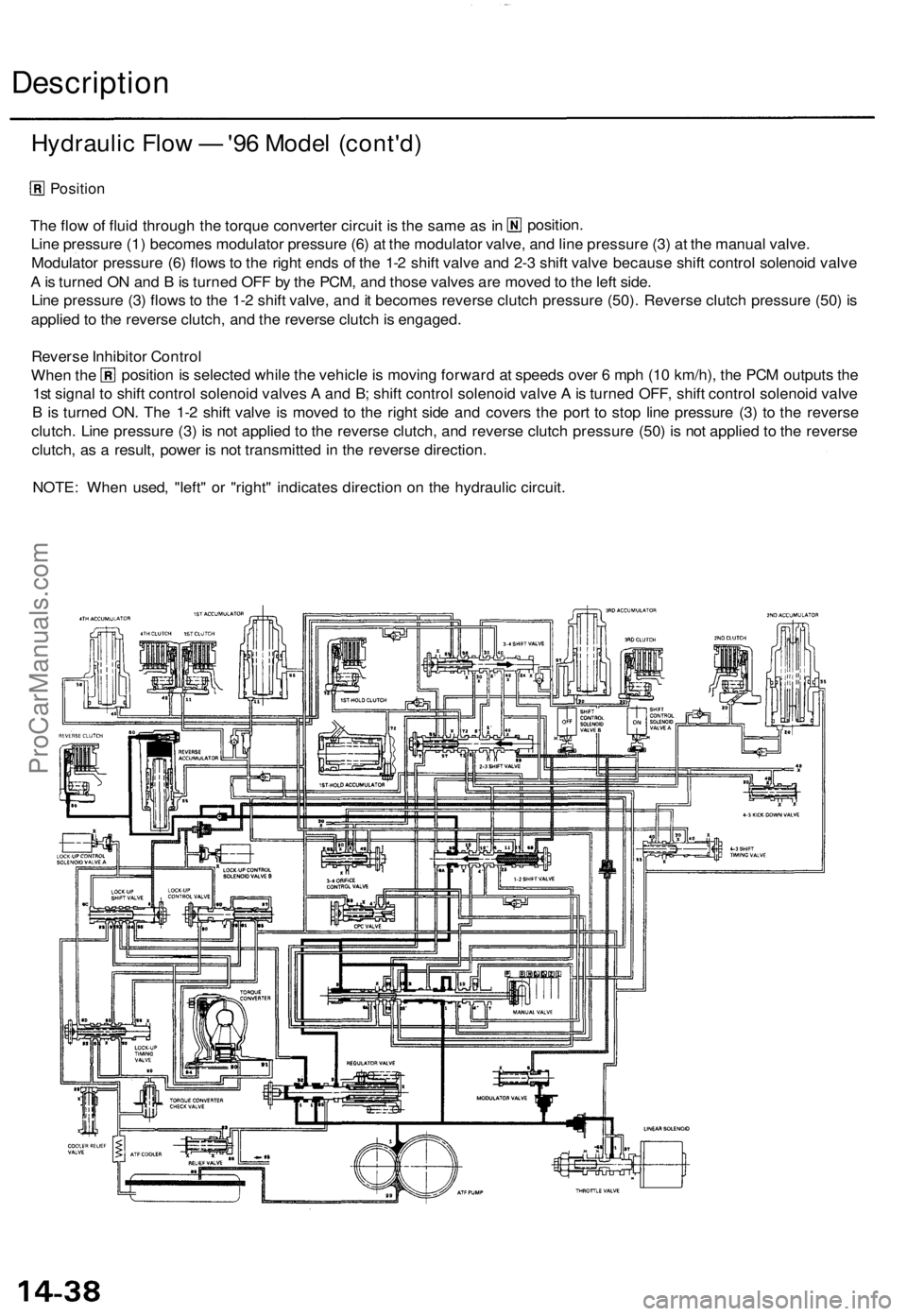
Description
Hydraulic Flow — '96 Model (cont'd)
Position
The flow of fluid through the torque converter circuit is the same as in
Line pressure (1) becomes modulator pressure (6) at the modulator valve, and line pressure (3) at the manual valve.
Modulator pressure (6) flows to the right ends of the 1-2 shift valve and 2-3 shift valve because shift control solenoid valve
A is turned ON and B is turned OFF by the PCM, and those valves are moved to the left side.
Line pressure (3) flows to the 1-2 shift valve, and it becomes reverse clutch pressure (50). Reverse clutch pressure (50) is
applied to the reverse clutch, and the reverse clutch is engaged.
position.
NOTE: When used, "left" or "right" indicates direction on the hydraulic circuit.
Reverse Inhibitor Control
When the
1st signal to shift control solenoid valves A and B; shift control solenoid valve A is turned OFF, shift control solenoid valve
B is turned ON. The 1-2 shift valve is moved to the right side and covers the port to stop line pressure (3) to the reverse
clutch. Line pressure (3) is not applied to the reverse clutch, and reverse clutch pressure (50) is not applied to the reverse
clutch, as a result, power is not transmitted in the reverse direction.
position is selected while the vehicle is moving forward at speeds over 6 mph (10 km/h), the PCM outputs theProCarManuals.com
Page 303 of 1771
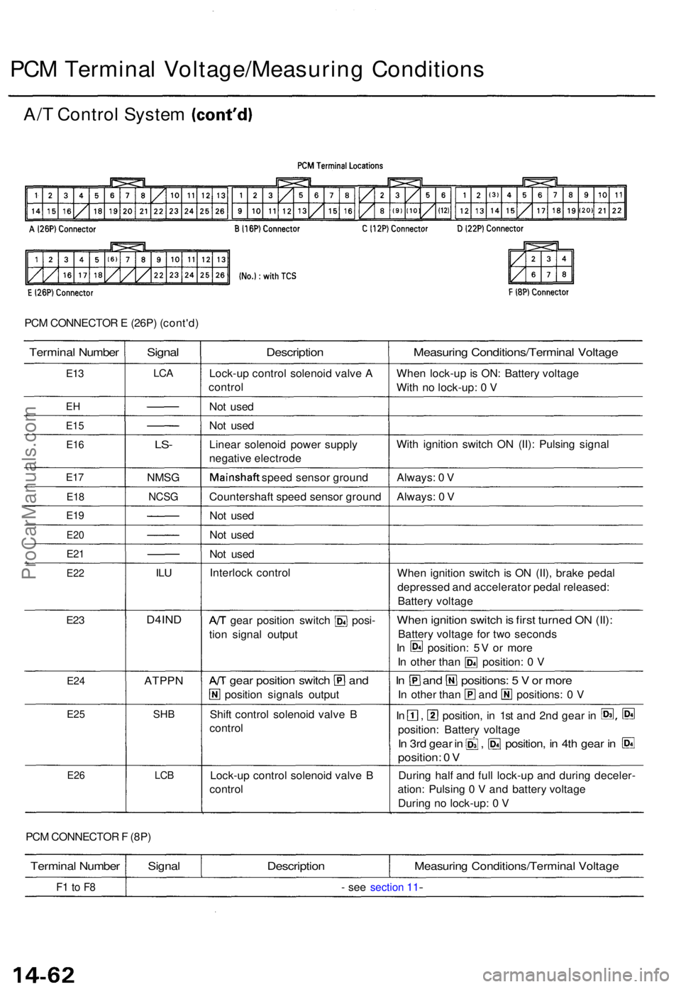
PCM CONNECTO R E (26P ) (cont'd )
Termina l Numbe r
E13
EH
E1 5
E16
E17
E1 8
E19
E2 0
E21
E2 2
E23
E2 4
E2 5
E2 6
Signa l
LCA
LS-
NMS G
NCSG
ILU
D4IN D
ATPP N
SHB
LCB
Descriptio n
Lock-up contro l solenoi d valv e A
contro l
No t use d
No t use d
Linea r solenoi d powe r suppl y
negativ e electrod e
Mainshaf t speed senso r groun d
Countershaf t spee d senso r groun d
No t use d
No t use d
No t use d
Interloc k contro l
A/T gea r positio n switc h posi -
tio n signa l outpu t
A/T gea r positio n switc h an d
positio n signal s outpu t
Shif t contro l solenoi d valv e B
contro l
Lock-u p contro l solenoi d valv e B
contro l
Measurin g Conditions/Termina l Voltag e
When lock-u p is ON : Batter y voltag e
Wit h n o lock-up : 0 V
Wit h ignitio n switc h O N (II) : Pulsin g signa l
Always : 0 V
Always : 0 V
Whe n ignitio n switc h i s O N (II) , brak e peda l
depresse d an d accelerato r peda l released :
Batter y voltag e
When ignitio n switc h is firs t turne d O N (II) :
Batter y voltag e fo r tw o second s
In position : 5 V o r mor e
In othe r tha n position : 0 V
In an d positions : 5 V or mor e
In othe r tha n an d positions : 0 V
In , position , i n 1s t an d 2n d gea r i n S3 , @
position : Batter y voltag e
In 3r d gea r i n , position , i n 4t h gea r i n E
position : 0 V
Durin g hal f an d ful l lock-u p an d durin g deceler -
ation : Pulsin g 0 V an d batter y voltag e
Durin g n o lock-up: 0 V
PC M CONNECTO R F (8P )
Termina l Numbe r
F1 t o F 8
Signa lDescriptio nMeasuring Conditions/Termina l Voltag e
- se e section 11-
A/ T Contro l Syste m (cont'd )
PCM Termina l Voltage/Measurin g Condition s
ProCarManuals.com
Page 310 of 1771
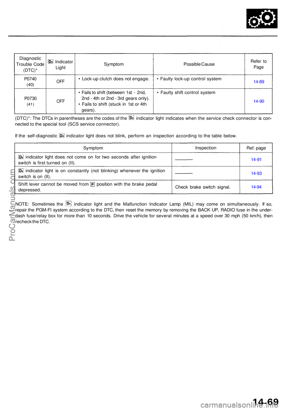
Diagnostic
Troubl e Cod e
(DTC) *
P0740
(40)
P073 0
(41)
Indicato r
Ligh t
OFF
OF F
Sympto m
• Lock-u p clutc h doe s no t engage .
• Fail s to shif t (betwee n 1s t - 2nd ,
2n d - 4t h o r 2n d - 3r d gear s only) .
• Fail s t o shif t (stuc k i n 1s t o r 4t h
gears) .
Possibl e Caus e
• Fault y lock-u p contro l syste m
• Fault y shif t contro l syste mRefer t o
Pag e
14-8 9
14-9 0
(DTC)* : Th e DTC s in parenthese s ar e th e code s o f th e indicato r ligh t indicate s whe n th e servic e chec k connecto r i s con -
necte d t o th e specia l too l (SC S servic e connector) .
If th e self-diagnosti c indicato r ligh t doe s no t blink , perfor m a n inspectio n accordin g t o th e tabl e below .
Sympto m
indicato r ligh t doe s no t com e o n fo r tw o second s afte r ignitio n
switc h i s firs t turne d o n (II) .
indicato r ligh t i s o n constantl y (no t blinking ) wheneve r th e ignitio n
switc h i s o n (II) .
Shif t leve r canno t b e move d fro m positio n wit h th e brak e peda l
depressed . Inspectio
n
Chec k brak e switc h signal . Ref.
page
14-9 1
14-9 3
14-9 4
NOTE : Sometime s th e indicato r ligh t an d th e Malfunctio n Indicato r Lam p (MIL ) ma y com e o n simultaneously . I f so ,
repai r th e PGM-F I syste m accordin g t o th e DTC , the n rese t th e memor y b y removin g th e BAC K UP , RADI O fus e in th e under -
das h fuse/rela y bo x fo r mor e tha n 1 0 seconds . Driv e th e vehicl e fo r severa l minute s a t a spee d ove r 3 0 mp h (5 0 km/h) , the n
rechec k th e DTC .
ProCarManuals.com
Page 512 of 1771
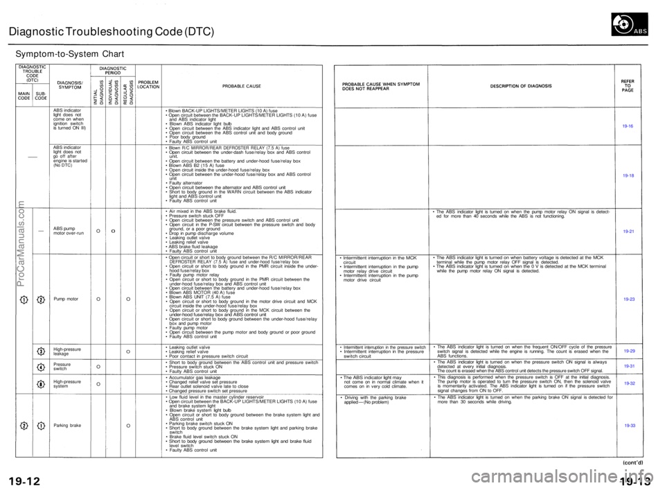
Diagnostic Troubleshootin g Cod e (DTC )
Symptom-to-Syste m Char t
ABS indicato r
ligh t doe s no t
com e o n whe n
ignitio n switc h
i s turne d O N III )
AB S indicato r
ligh t doe s no t
go of f afte rengin e is starte d(No DTC )
ABS pum p
moto r over-ru n
Pum p moto r
High-pressur eleakage
Pressur eswitch
High-pressur esystem
Parkin g brak e
O
O
O
O0
O
O
O
• Blow n BACK-U P LIGHTS/METE R LIGHT S (1 0 A ) fus e
• Ope n circui t betwee n th e BACK-U P LIGHTS/METE R LIGHT S (1 0 A ) fus e
an d AB S indicato r ligh t
• Blow n AB S indicato r ligh t bul b
• Ope n circui t betwee n th e AB S indicato r ligh t an d AB S contro l uni t
• Ope n circui t betwee n th e AB S contro l uni t an d bod y groun d
• Poo r bod y groun d
• Fault y AB S contro l uni t
• Blow n R/ C MIRROR/REA R DEFROSTE R RELA Y (7. 5 A ) fus e• Ope n circui t betwee n th e under-das h fuse/rela y bo x an d AB S contro lunit.• Ope n circui t betwee n th e batter y an d under-hoo d fuse/rela y bo x
• Blow n AB S B 2 (1 5 A ) fus e
• Ope n circui t insid e th e under-hoo d fuse/rela y bo x
• Ope n circui t betwee n th e under-hoo d fuse/rela y bo x an d AB S contro l
unit• Fault y alternato r• Ope n circui t betwee n th e alternato r an d AB S contro l uni t• Shor t t o bod y groun d i n th e WAR N circui t betwee n th e AB S indicato rlight an d AB S contro l uni t• Fault y AB S contro l uni t
• Ai r mixe d i n th e AB S brak e fluid .
• Pressur e switc h stuc k OF F
• Ope n circui t betwee n th e pressur e switc h an d AB S contro l uni t
• Ope n circui t i n th e P-S W circui t betwee n th e pressur e switc h an d bod y
ground , o r a poo r groun d
• Dro p in pum p discharg e volum e
• Leakin g outle t valv e
• Leakin g relie f valv e
• AB S brak e flui d leakag e
• Fault y AB S contro l uni t
• Ope n circui t o r shor t t o bod y groun d betwee n th e R/ C MIRROR/REA R
DEFROSTER RELA Y (7. 5 A ) fus e an d under-hoo d fuse/rela y bo x• Ope n circui t o r shor t t o bod y groun d i n th e PM R circui t insid e th e under -
hoo d fuse/rela y bo x
• Fault y pum p moto r rela y
• Ope n circui t o r shor t t o bod y groun d i n th e PM R circui t betwee n th e
under-hoo d fuse/rela y bo x an d AB S contro l uni t
• Ope n circui t betwee n th e batter y an d under-hoo d fuse/rela y bo x
• Blow n AB S MOTO R (4 0 A ) fus e
• Blow n AB S UNI T (7. 5 A ) fus e
• Ope n circui t o r shor t t o bod y groun d i n th e moto r driv e circui t an d MC K
circui t insid e th e under-hoo d fuse/rela y bo x
• Ope n circui t o r shor t t o bod y groun d i n th e MC K circui t betwee n th e
under-hoo d fuse/rela y bo x an d AB S contro l uni t• Ope n circui t o r shor t t o bod y groun d betwee n th e under-hoo d fuse/rela y
bo x an d pum p moto r
• Fault y pum p moto r
• Ope n circui t betwee n th e pum p moto r an d bod y groun d o r poo r groun d
• Fault y AB S contro l uni t
• Leakin g outle t valv e
• Leakin g relie f valv e
• Poo r contac t i n pressur e switc h circui t
• Shor t t o bod y groun d betwee n th e AB S contro l uni t an d pressur e switc h
• Pressure switch stuc k O N
• Fault y AB S contro l uni t
• Accumulato r ga s leakag e
• Change d relie f valv e se t pressur e
• Rea r outle t solenoi d valv e lat e t o clos e
• Change d pressur e switc h se t pressur e
• Lo w flui d leve l i n th e maste r cylinde r reservoi r
• Ope n circui t betwee n th e BACK-U P LIGHTS/METE R LIGHT S (1 0 A ) fus e
an d brak e syste m ligh t
• Blow n brak e syste m ligh t bul b
• Ope n circui t o r shor t t o bod y groun d betwee n th e brak e syste m ligh t an d
AB S contro l uni t
• Parkin g brak e switc h stuc k O N
• Shor t t o bod y groun d betwee n th e brak e syste m ligh t an d parkin g brak e
switc h
• Brak e flui d leve l switc h stuc k O N
• Shor t t o bod y groun d betwee n th e brak e syste m ligh t an d brak e flui dleve l switc h
• Fault y AB S contro l uni t
• Intermitten t interruptio n in th e MC Kcircui t• Intermitten t interruptio n in th e pum pmotor rela y driv e circui t• Intermitten t interruptio n i n th e pum pmotor driv e circui t
• Intermitten t interruptio n i n th e pressur e switc h• Intermitten t interruptio n i n th e pressur eswitch circui t
• Th e AB S indicato r ligh t ma ynot com e o n i n norma l climat e whe n i t
come s o n i n ver y col d climate .
• Drivin g wit h th e parkin g brak e
applie d — (No problem ) •
Th e AB S indicato r ligh t i s turne d o n whe n th e pum p moto r rela y O N signa l i s detect -
e d fo r mor e tha n 4 0 second s whil e th e AB S i s no t functioning .
• Th e AB S indicato r ligh t i s turne d o n whe n batter y voltag e is detecte d a t th e MC Ktermina l whil e th e pum p moto r rela y OF F signa l i s detected .• Th e AB S indicato r ligh t i s turne d o n whe n th e 0 V is detecte d a t th e MC K termina lwhile th e pum p moto r rela y O N signa l i s detected .
• Th e AB S indicato r ligh t i s turne d o n whe n th e frequen t ON/OF F cycl e o f th e pressur e
switc h signa l i s detecte d whil e th e engin e i s running . Th e coun t i s erase d whe n th e
AB S functions .
• Th e AB S indicato r ligh t i s turne d o n whe n th e pressur e switc h O N signa l i s alway s
detecte d a t ever y initia l diagnosis .
Th e coun t i s erase d whe n th e AB S contro l uni t detect s th e pressur e switc h OF F signal .
• Thi s diagnosi s i s performe d whe n th e pressur e switc h i s OF F a t th e initia l diagnosis .
Th e pum p moto r i s operate d t o tur n th e pressur e switc h ON , the n th e solenoi d valv e
i s momentaril y activated . Th e AB S indicato r ligh t i s turne d o n i f th e pressur e switc h
signa l change s fro m O N to OFF .
• Th e AB S indicato r ligh t i s turne d o n whe n th e parkin g brak e O N signa l i s detecte d fo r
mor e tha n 3 0 second s whil e driving .
19-16
19-1 8
19-2 1
19-2 3
19-2 9
19-3 1
19-3 2
19-3 3
ProCarManuals.com
Page 522 of 1771
Troubleshooting Precautions
ABS Indicator Light
1. If the system is OK, the ABS indicator light goes off two seconds after turning the ignition switch ON (II) without start-
ing the engine. After starting the engine, the ABS indicator light comes on again and goes off after two seconds. This
occurs because the ABS control unit is activated by the IG2 power source.
2. The ABS indicator light comes on when the ABS control unit detects a problem in the system. However, even though
the system is normal, the ABS indicator light comes on, too, under the following conditions. To determine the actual
cause of problem, question the customer about the problem, talking the following conditions into consideration.
Only drive wheels rotate
One wheel stuck of drive wheels
Vehicle spin
ABS operate condition continue for long time
Signal disturbance
3. When a problem is detected and the ABS indicator light comes on, there are cases when the indicator light stays on
until the ignition switch is turned OFF, and cases when the indicator light goes off automatically when the system
returns normal. For the DTC 61 and 62, the indicator light goes off automatically when the system returns normal. For
all other codes, the indicator light stays on until the ignition switch is turned OFF.
4. For DTCs 12, 14, 16, 18, 21, 22, 23, 24, 51, 52 and 53, the indicator light goes off when the vehicle is driven again and
the signals are OK after the ignition switch is turned from OFF to ON (II). However, if the DTC is erased, the CPU is
reset and the indicator light goes off right after the engine is started if the signals are OK.
Diagnostic Trouble Code (DTC)
1. The DTC is not memorized if the CPU cannot be activated or the CPU fails and the indicator light comes on.
2. The memory can hold any number of DTCs. However, when the same DTC is detected more than once, the later one
is written over the old one. Therefore, when the same problem is detected repeatedly, it is memorized as one DTC.
3. The DTCs are indicated in the order of ascending number, not in the order they occur.
4. The DTCs are memorized in the EEPROM (non-volatile memory). Therefore, the memorized DTCs cannot be canceled
by disconnecting the battery. Perform the specified procedures to erase the DTCs.
Self-diagnosis
1. The
self-diagnosis
can be
classified
into
two
categories.
• Initial diagnosis: Performed right after the engine starts and until the ABS indicator light goes off.
• Regular diagnosis: Performed right after the initial diagnosis until the ignition switch is turned OFF.
2. When a problem is detected by self-diagnosis, the system
• Turns the ABS indicator light ON
• Memorizes the DTC
• Turns the fail-safe relay OFF
• Stops ABS controlProCarManuals.com
Page 530 of 1771
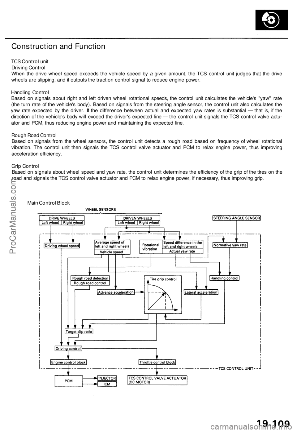
Construction and Function
TCS Control unit
Driving Control
When the drive wheel speed exceeds the vehicle speed by a given amount, the TCS control unit judges that the drive
wheels are slipping, and it outputs the traction control signal to reduce engine power.
Handling Control
Based on signals about right and left driven wheel rotational speeds, the control unit calculates the vehicle's "yaw" rate
(the turn rate of the vehicle's body). Based on signals from the steering angle sensor, the control unit also calculates the
yaw rate expected by the driver. If the difference between actual and expected yaw rates is substantial — that is, if the
direction of the vehicle's body will exceed the driver's expected line — the control unit signals the TCS control valve actu-
ator and PCM, thus reducing engine power and maintaining the expected line.
Rough Road Control
Based on signals from the wheel sensors, the control unit detects a rough road based on frequency of wheel rotational
vibration. The control unit then signals the TCS control valve actuator and PCM to relax engine power, thus improving
acceleration efficiency.
Grip Control
Based on signals about wheel speed and yaw rate, the control unit determines the efficiency of the grip of the tires on the
road and signals the TCS control valve actuator and PCM to relax engine power, if necessary, thus improving grip.
Main Control BlockProCarManuals.com