oil change ACURA TL 1995 Service Repair Manual
[x] Cancel search | Manufacturer: ACURA, Model Year: 1995, Model line: TL, Model: ACURA TL 1995Pages: 1771, PDF Size: 62.49 MB
Page 93 of 1771
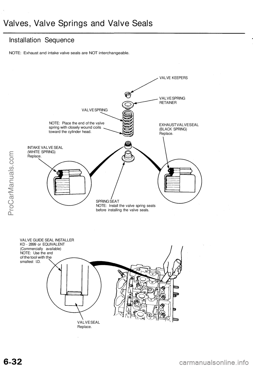
Valves, Valve Springs and Valve Seals
Installation Sequence
NOTE: Exhaust and intake valve seals are NOT interchangeable.
VALVE SPRING
NOTE: Place the end of the valve
spring with closely wound coils
toward the cylinder head.
INTAKE VALVE SEAL
(WHITE SPRING)
Replace.
VALVE KEEPERS
VALVE SPRING
RETAINER
EXHAUST VALVE SEAL
(BLACK SPRING)
Replace.
SPRING SEAT
NOTE: Install the valve spring seats
before installing the valve seals.
VALVE GUIDE SEAL INSTALLER
KD - 2899 or EQUIVALENT
(Commercially available)
NOTE: Use the end
of the tool with the
smallest I.D.
VALVE SEAL
Replace.ProCarManuals.com
Page 101 of 1771
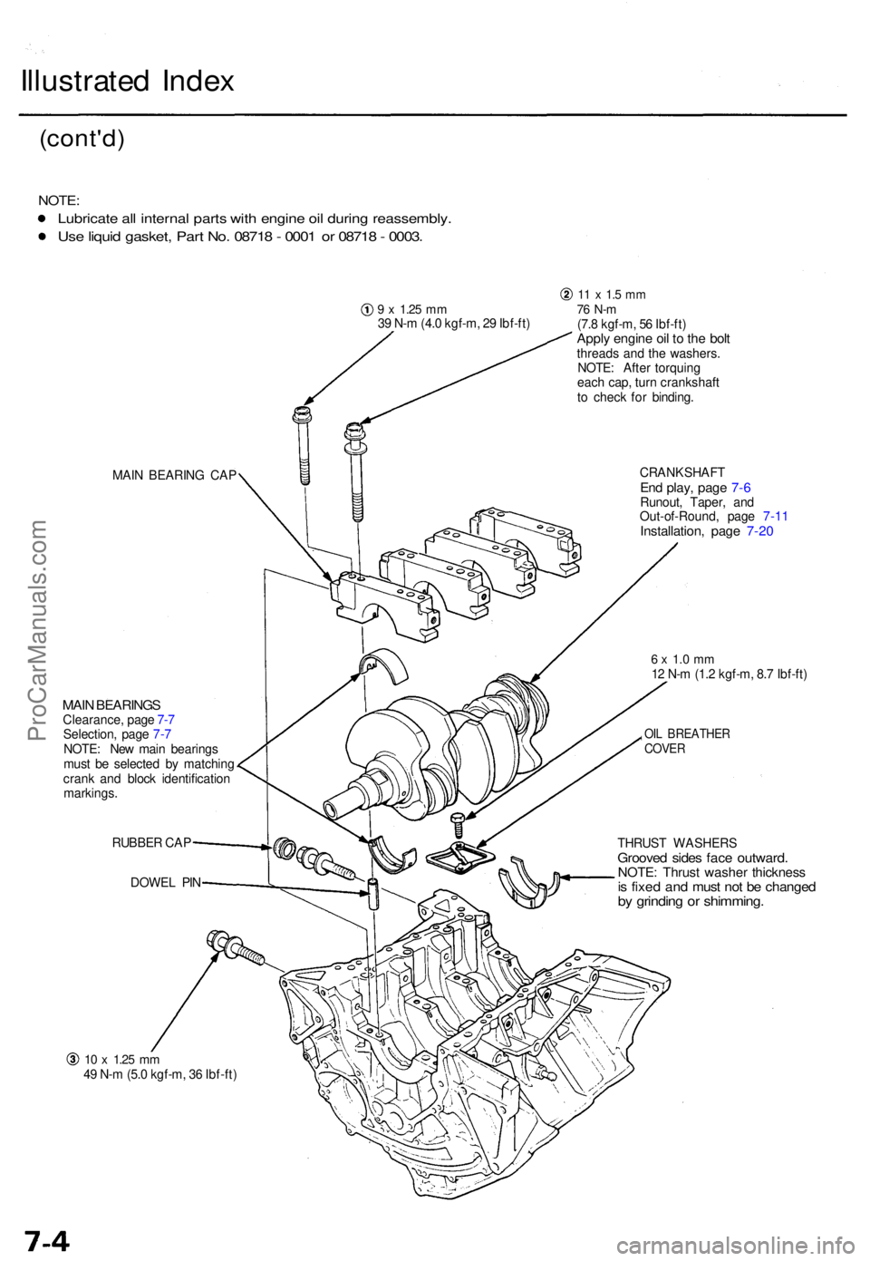
Illustrated Inde x
(cont'd )
NOTE:
Lubricat e al l interna l part s wit h engin e oi l durin g reassembly .
Use liqui d gasket , Par t No . 0871 8 - 000 1 o r 0871 8 - 0003 .
9 x 1.2 5 mm39 N- m (4. 0 kgf-m , 2 9 Ibf-ft )
11 x 1. 5 m m76 N- m(7.8 kgf-m , 5 6 Ibf-ft )Apply engin e oi l t o th e bol tthread s an d th e washers .
NOTE : Afte r torquin g
eac h cap , tur n crankshaf t
t o chec k fo r binding .
MAI N BEARIN G CA P
MAIN BEARING SClearance , pag e 7- 7
Selection , pag e 7- 7
NOTE : Ne w mai n bearing s
mus t b e selecte d b y matchin g
cran k an d bloc k identificatio n
markings .
RUBBE R CA P
DOWE L PI N CRANKSHAF
T
End play , pag e 7- 6Runout , Taper , an d
Out-of-Round , pag e 7-1 1
Installation , pag e 7-2 0
6 x 1. 0 m m12 N- m (1. 2 kgf-m , 8. 7 Ibf-ft )
OIL BREATHE RCOVER
THRUS T WASHER SGrooved side s fac e outward .NOTE: Thrus t washe r thicknes sis fixe d an d mus t no t b e change dby grindin g o r shimming .
10 x 1.2 5 mm49 N- m (5. 0 kgf-m , 3 6 Ibf-ft )
ProCarManuals.com
Page 127 of 1771
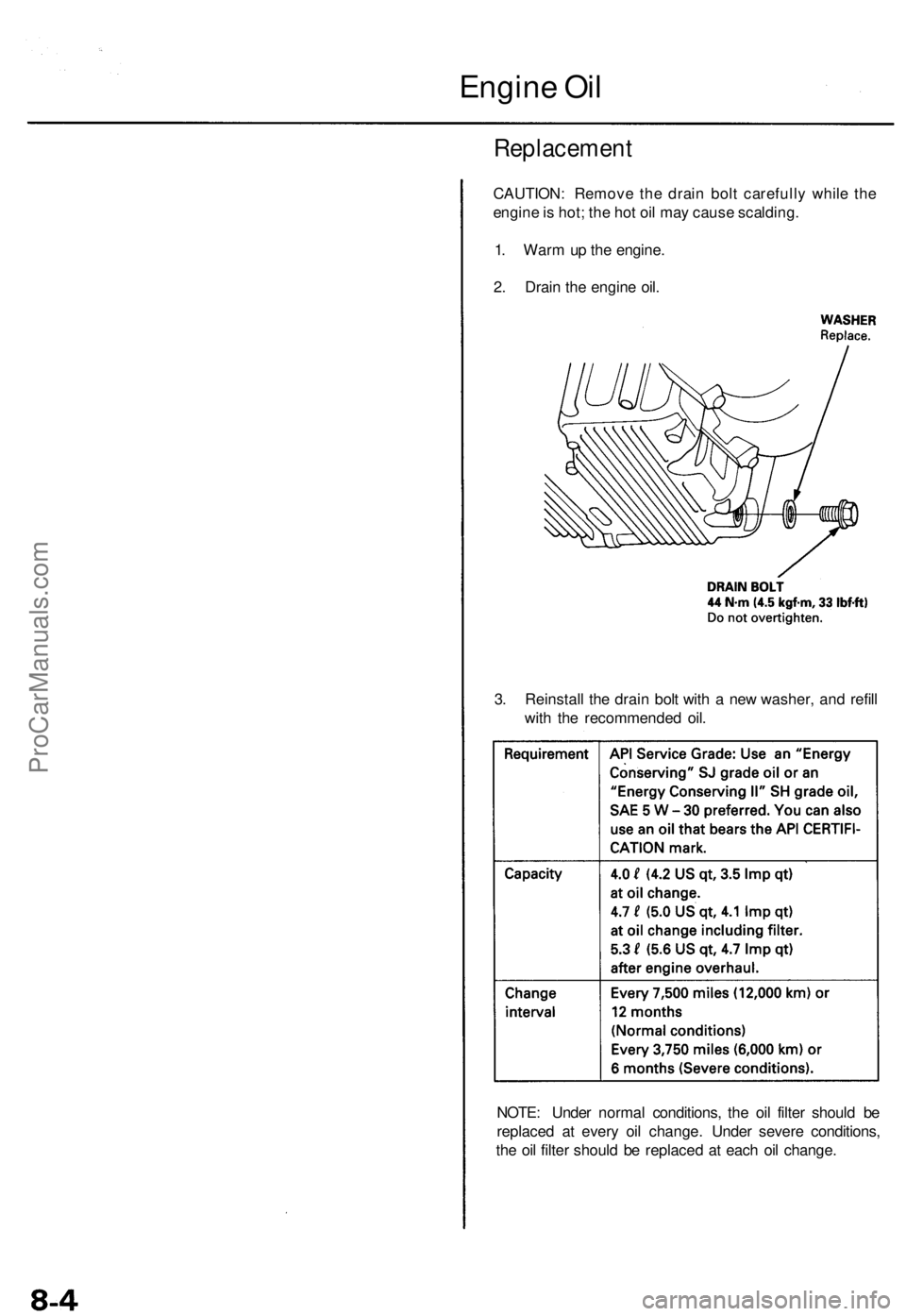
Engine Oi l
Replacemen t
CAUTION: Remov e th e drai n bol t carefull y whil e th e
engin e is hot ; th e ho t oi l ma y caus e scalding .
1 . War m u p th e engine .
2 . Drai n th e engin e oil .
3 . Reinstal l th e drai n bol t wit h a ne w washer , an d refil l
wit h th e recommende d oil .
NOTE : Unde r norma l conditions , th e oi l filte r shoul d b e
replace d a t ever y oi l change . Unde r sever e conditions ,
th e oi l filte r shoul d b e replace d a t eac h oi l change .
ProCarManuals.com
Page 434 of 1771
Maintenance
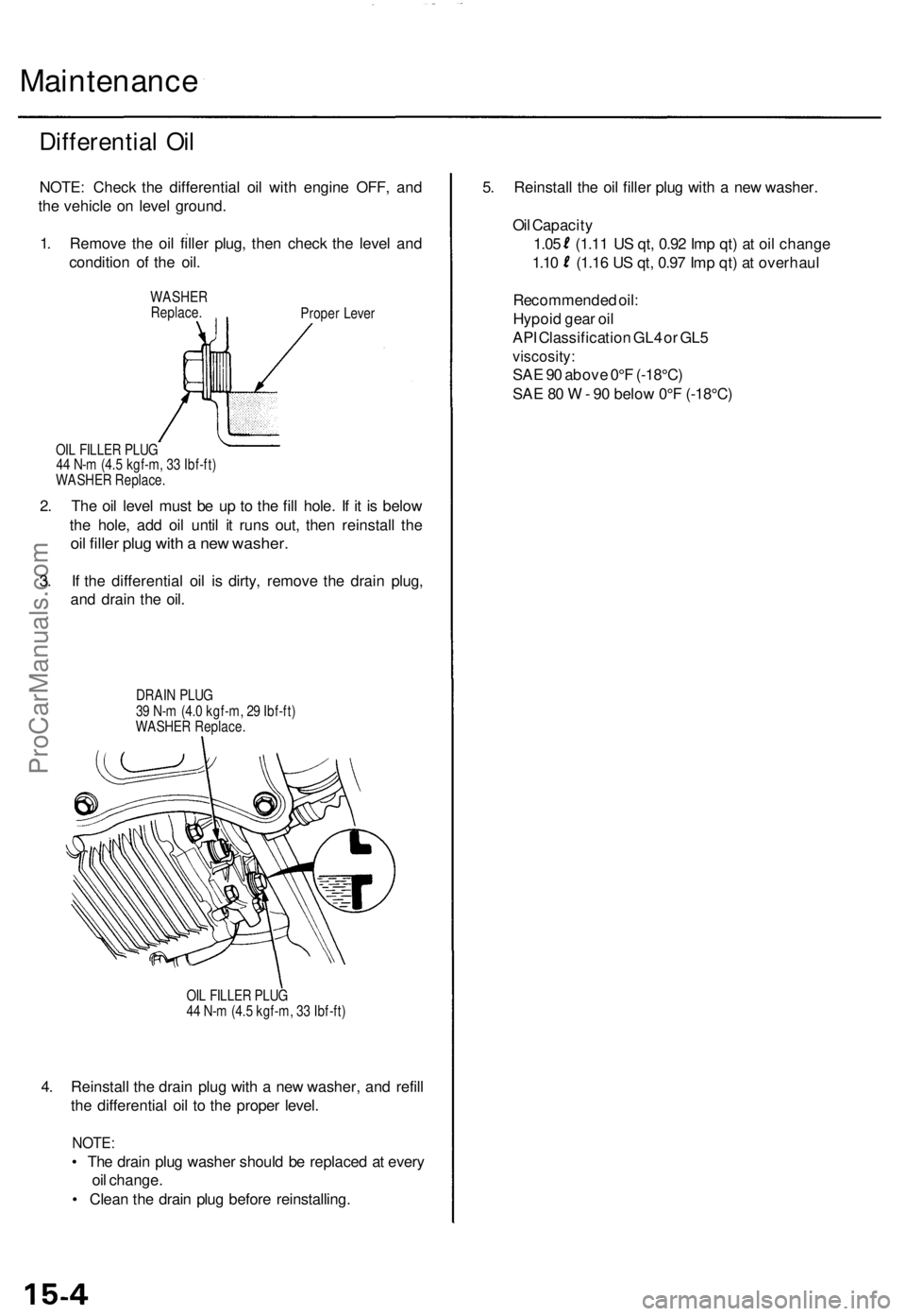
Differential Oi l
NOTE : Chec k th e differentia l oi l wit h engin e OFF , an d
th e vehicl e o n leve l ground .
1 . Remov e th e oi l fille r plug , the n chec k th e leve l an d
conditio n o f th e oil .
WASHERReplace .Proper Leve r
OI L FILLE R PLU G
4 4 N- m (4. 5 kgf-m , 3 3 Ibf-ft )
WASHE R Replace .
2. Th e oi l leve l mus t b e u p t o th e fil l hole . I f i t i s belo w
th e hole , ad d oi l unti l i t run s out , the n reinstal l th e
oil fille r plu g wit h a ne w washer .
3. I f th e differentia l oi l i s dirty , remov e th e drai n plug ,
an d drai n th e oil .
DRAI N PLU G
3 9 N- m (4. 0 kgf-m , 2 9 Ibf-ft )
WASHE R Replace .
OI L FILLE R PLU G
4 4 N- m (4. 5 kgf-m , 3 3 Ibf-ft )
4. Reinstal l th e drai n plu g wit h a ne w washer , an d refil l
th e differentia l oi l t o th e prope r level .
NOTE :
• Th e drai n plu g washe r shoul d b e replace d a t ever y
oi l change .
• Clea n th e drai n plu g befor e reinstalling . 5
. Reinstal l th e oi l fille r plu g wit h a ne w washer .
Oi l Capacit y
1.0 5 (1.1 1 U S qt , 0.9 2 Im p qt ) a t oi l chang e
1.10 (1.1 6 U S qt , 0.9 7 Im p qt ) a t overhau l
Recommende d oil :
Hypoi d gea r oi l
AP I Classificatio n GL 4 o r GL 5
viscosity :
SAE 9 0 abov e 0° F (-18°C )
SA E 8 0 W - 9 0 belo w 0° F (-18°C )
ProCarManuals.com
Page 778 of 1771
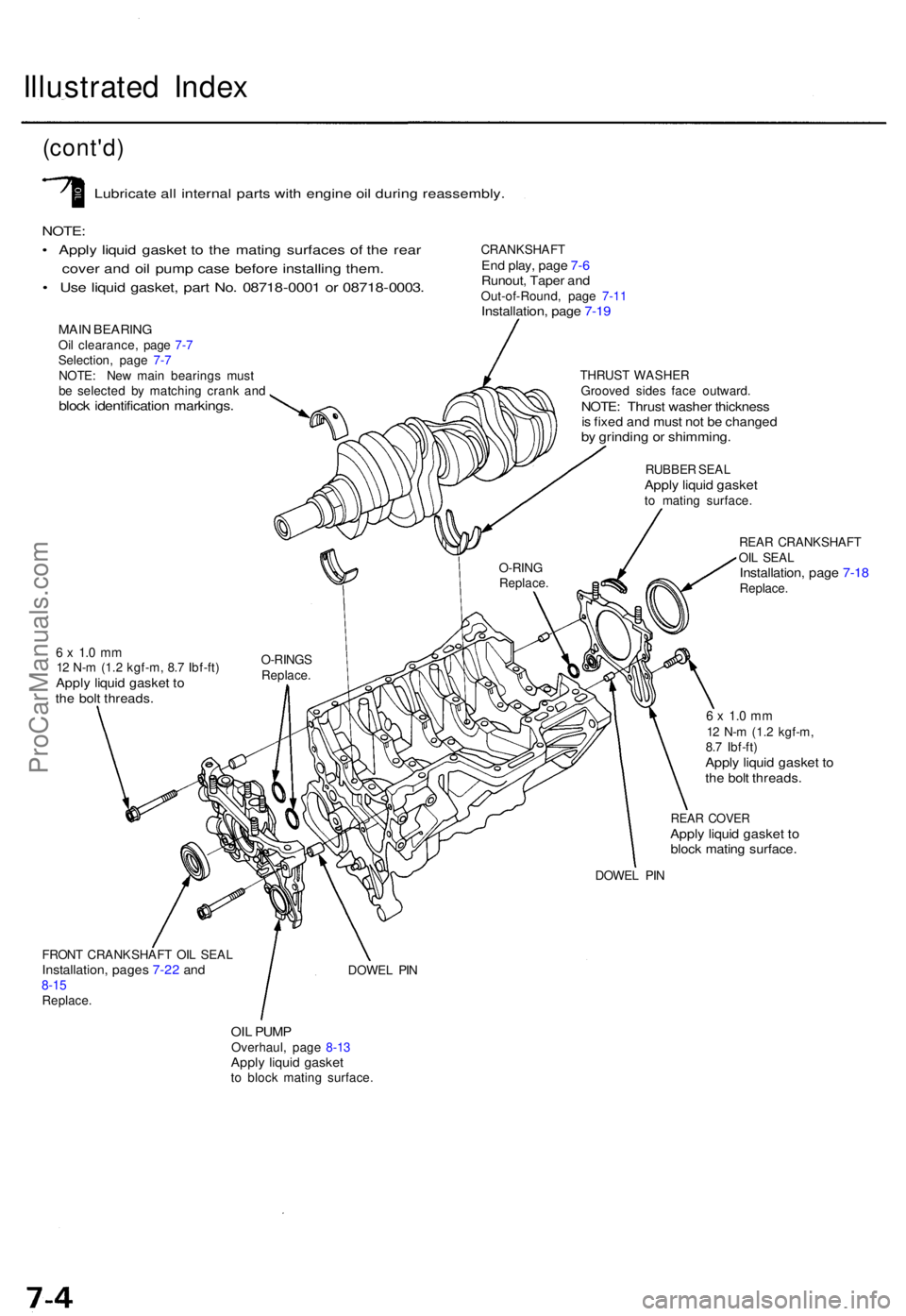
Illustrated Inde x
(cont'd )
Lubricat e al l interna l part s wit h engin e oi l durin g reassembly .
NOTE:
• Appl y liqui d gaske t t o th e matin g surface s o f th e rea r
cove r an d oi l pum p cas e befor e installin g them .
• Us e liqui d gasket , par t No . 0871 8-000 1 o r 0871 8-0003 .
MAIN BEARIN GOil clearance , pag e 7- 7
Selection , pag e 7- 7
NOTE : Ne w mai n bearing s mus t
b e selecte d b y matchin g cran k an d
bloc k identificatio n markings .
CRANKSHAF TEnd play , pag e 7- 6Runout , Tape r an dOut-of-Round , pag e 7-1 1Installation , pag e 7-1 9
THRUS T WASHE R
Groove d side s fac e outward .
NOTE: Thrus t washe r thicknes sis fixe d an d mus t no t b e change dby grindin g o r shimming .
RUBBER SEA LApply liqui d gaske tto matin g surface .
REA R CRANKSHAF T
OI L SEA L
Installation , pag e 7-1 8Replace .
6 x 1. 0 m m12 N- m (1. 2 kgf-m , 8. 7 Ibf-ft )Apply liqui d gaske t t oth e bol t threads .
6 x 1. 0 m m12 N- m (1. 2 kgf-m ,
8. 7 Ibf-ft )
Apply liqui d gaske t t oth e bol t threads .
REAR COVE RApply liqui d gaske t t obloc k matin g surface .
DOWEL PI N
FRON T CRANKSHAF T OI L SEA L
Installation , page s 7-2 2 an d8-1 5Replace .
DOWEL PI N
OIL PUM POverhaul , pag e 8-1 3Appl y liqui d gaske tto bloc k matin g surface . O-RIN
G
Replace .
O-RINGS
Replace .
ProCarManuals.com
Page 806 of 1771
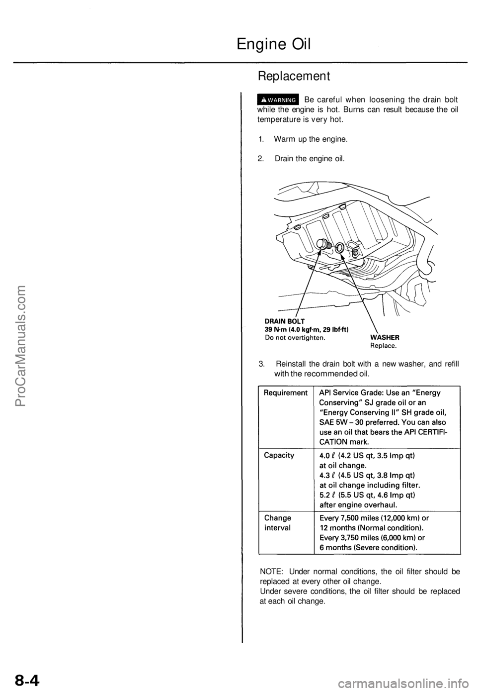
NOTE: Unde r norma l conditions , th e oi l filte r shoul d b e
replace d a t ever y othe r oi l change .
Unde r sever e conditions , th e oi l filte r shoul d b e replace d
a t eac h oi l change .
Replacemen t
Be carefu l whe n loosenin g th e drai n bol t
whil e th e engin e i s hot . Burn s ca n resul t becaus e th e oi l
temperatur e is ver y hot .
1 . War m u p th e engine .
2 . Drai n th e engin e oil .
3 . Reinstal l th e drai n bol t wit h a ne w washer , an d refil l
with th e recommende d oil .
Engin e Oi l
ProCarManuals.com
Page 1095 of 1771
Maintenance
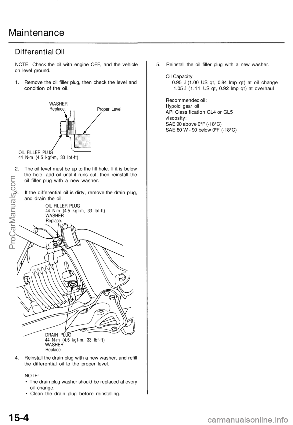
Differential Oi l
NOTE : Chec k th e oi l wit h engin e OFF , an d th e vehicl e
o n leve l ground .
1 . Remov e th e oi l fille r plug , the n chec k th e leve l an d
conditio n o f th e oil .
WASHE R
Replace .
Proper Leve l
OIL FILLE R PLU G44 N- m (4. 5 kgf-m , 3 3 Ibf-ft )
2. Th e oi l leve l mus t b e u p t o th e fil l hole . I f i t i s belo w
th e hole , ad d oi l unti l i t run s out , the n reinstal l th e
oi l fille r plu g wit h a ne w washer .
3 . I f th e differentia l oi l i s dirty , remov e th e drai n plug ,
an d drai n th e oil .
OIL FILLE R PLU G
4 4 N- m (4. 5 kgf-m , 3 3 Ibf-ft )
WASHE R
Replace .
DRAI N PLU G
4 4 N- m (4. 5 kgf-m , 3 3 Ibf-ft )
WASHE R
Replace .
4. Reinstal l th e drai n plu g wit h a ne w washer , an d refil l
th e differentia l oi l t o th e prope r level .
NOTE :
• Th e drai n plu g washe r shoul d b e replace d a t ever y
oi l change .
• Clea n th e drai n plu g befor e reinstalling . 5
. Reinstal l th e oi l fille r plu g wit h a ne w washer .
Oi l Capacit y
0.9 5 (1.0 0 U S qt , 0.8 4 Im p qt) at oi l chang e
1.05 (1.1 1 U S qt , 0.9 2 Im p qt ) a t overhau l
Recommende d oil :
Hypoi d gea r oi l
AP I Classificatio n GL 4 o r GL 5
viscosity :
SAE 9 0 abov e 0°F (-18°C )
SA E 8 0 W - 9 0 belo w 0° F (-18°C )
ProCarManuals.com
Page 1326 of 1771
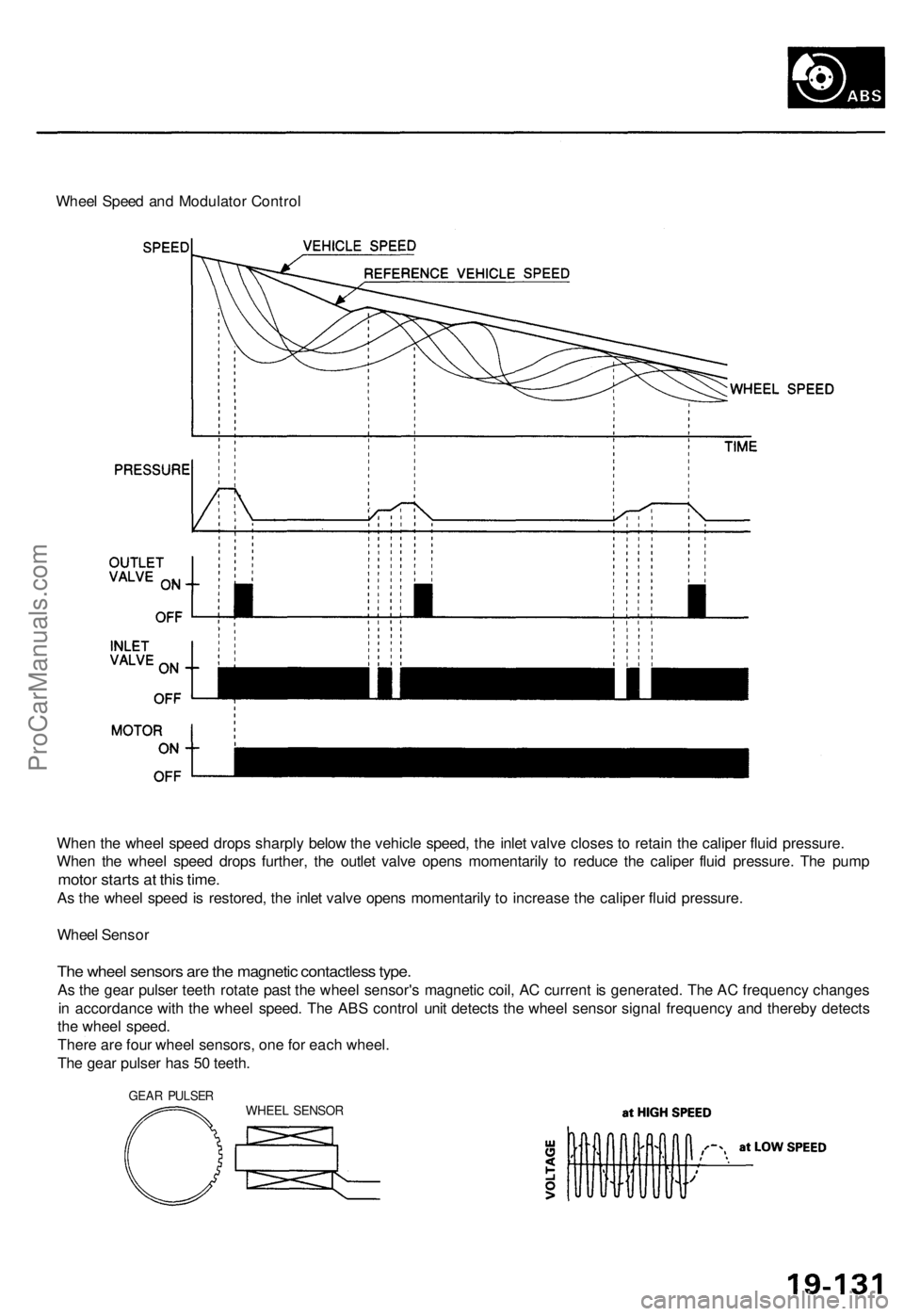
Wheel Speed and Modulator Control
When the wheel speed drops sharply below the vehicle speed, the inlet valve closes to retain the caliper fluid pressure.
When the wheel speed drops further, the outlet valve opens momentarily to reduce the caliper fluid pressure. The pump
motor starts at this time.
As the wheel speed is restored, the inlet valve opens momentarily to increase the caliper fluid pressure.
Wheel Sensor
The wheel sensors are the magnetic contactless type.
As the gear pulser teeth rotate past the wheel sensor's magnetic coil, AC current is generated. The AC frequency changes
in accordance with the wheel speed. The ABS control unit detects the wheel sensor signal frequency and thereby detects
the wheel speed.
There are four wheel sensors, one for each wheel.
The gear pulser has 50 teeth.
GEAR PULSER
WHEEL SENSORProCarManuals.com
Page 1493 of 1771
Description
Outline
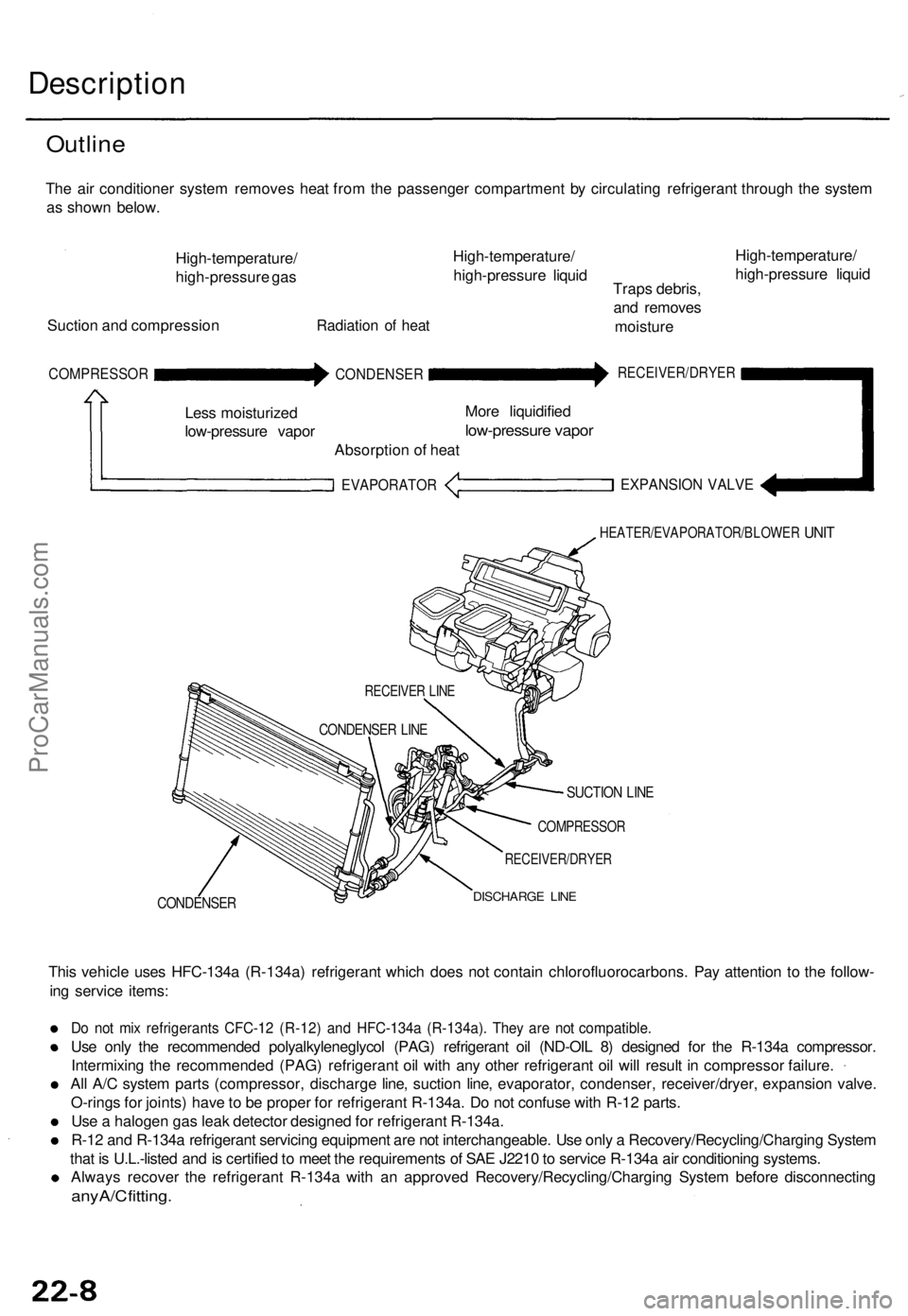
The air conditioner system removes heat from the passenger compartment by circulating refrigerant through the system
as shown below.
High-temperature/
high-pressure gas
Suction and compression
Radiation of heat
High-temperature/
high-pressure liquid
Traps debris,
and removes
moisture
High-temperature/
high-pressure liquid
COMPRESSOR
Less moisturized
low-pressure vapor
CONDENSER
Absorption of heat
EVAPORATOR
More liquidified
low-pressure vapor
RECEIVER/DRYER
EXPANSION VALVE
HEATER/EVAPORATOR/BLOWER
UNIT
CONDENSER
SUCTION LINE
COMPRESSOR
RECEIVER/DRYER
DISCHARGE LINE
This vehicle uses HFC-134a (R-134a) refrigerant which does not contain chlorofluorocarbons. Pay attention to the follow-
ing service items:
Do not mix refrigerants CFC-12 (R-12) and HFC-134a (R-134a). They are not compatible.
Use only the recommended polyalkyleneglycol (PAG) refrigerant oil (ND-OIL 8) designed for the R-134a compressor.
Intermixing the recommended (PAG) refrigerant oil with any other refrigerant oil will result in compressor failure.
All A/C system parts (compressor, discharge line, suction line, evaporator, condenser, receiver/dryer, expansion valve.
O-rings for joints) have to be proper for refrigerant R-134a. Do not confuse with R-12 parts.
Use a halogen gas leak detector designed for refrigerant R-134a.
R-12 and R-134a refrigerant servicing equipment are not interchangeable. Use only a Recovery/Recycling/Charging System
that is U.L.-listed and is certified to meet the requirements of SAE J2210 to service R-134a air conditioning systems.
Always recover the refrigerant R-134a with an approved Recovery/Recycling/Charging System before disconnecting
any A/C fitting.
RECEIVER LINE
CONDENSER LINEProCarManuals.com
Page 1525 of 1771
Clutch Inspectio n
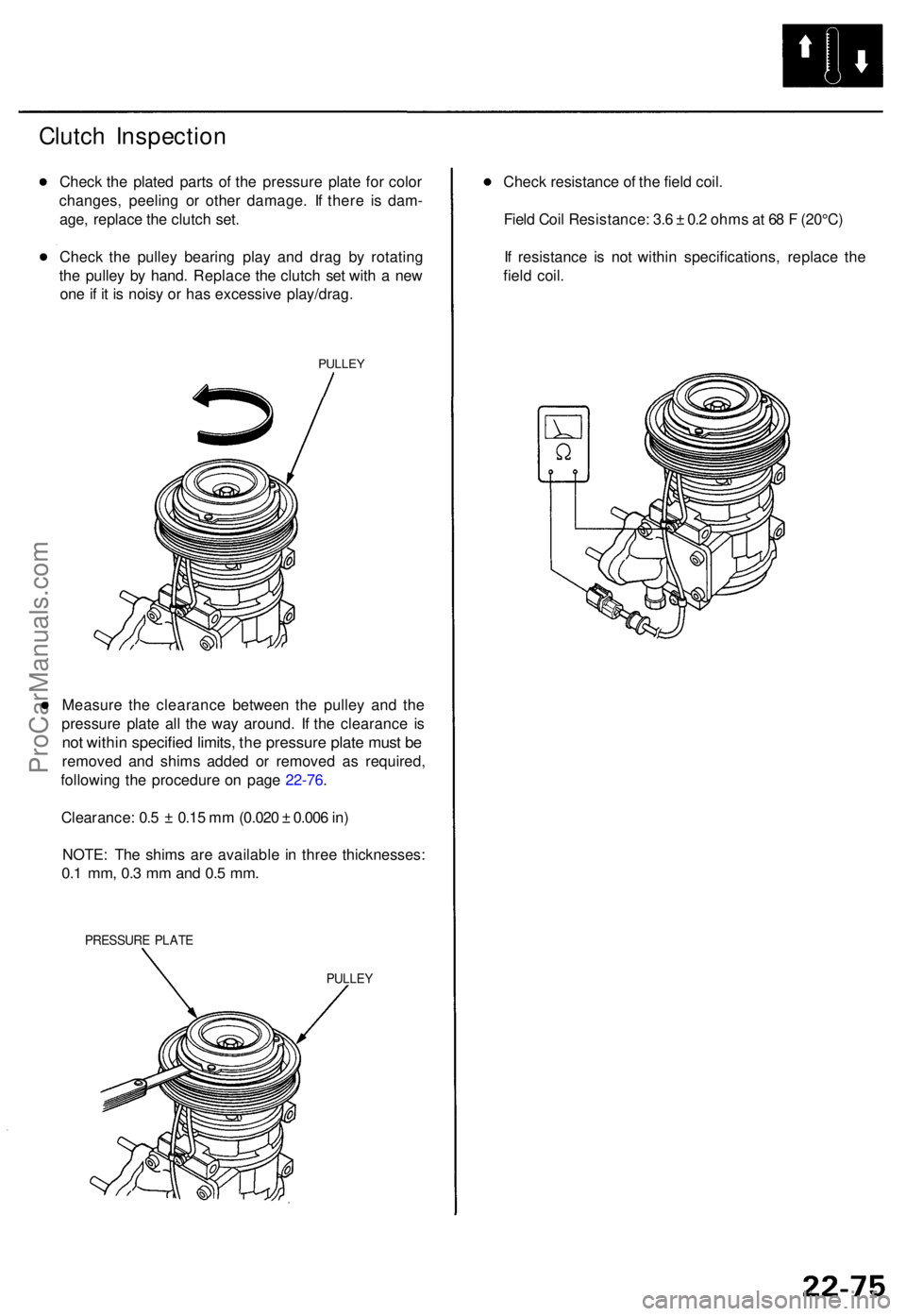
Check th e plate d part s o f th e pressur e plat e fo r colo r
changes , peelin g o r othe r damage . I f ther e i s dam -
age , replac e th e clutc h set .
Chec k th e pulle y bearin g pla y an d dra g b y rotatin g
th e pulle y b y hand . Replac e th e clutc h se t wit h a ne w
on e if i t i s nois y o r ha s excessive play/drag.
PULLEY
Measur e th e clearanc e betwee n th e pulle y an d th e
pressur e plat e al l th e wa y around . I f th e clearanc e i s
no t withi n specifie d limits , th e pressur e plat e mus t b e
remove d an d shim s added or remove d a s required ,
followin g th e procedur e o n pag e 22-76 .
Clearance : 0. 5 ± 0.1 5 m m (0.02 0 ± 0.00 6 in )
NOTE : Th e shim s ar e availabl e i n thre e thicknesses :
0.1 mm , 0. 3 m m an d 0. 5 mm .
PRESSUR E PLAT E
PULLE Y
Check resistanc e o f th e fiel d coil .
Fiel d Coi l Resistance : 3. 6 ± 0. 2 ohm s a t 6 8 F (20°C )
I f resistanc e i s no t withi n specifications , replac e th e
fiel d coil .
ProCarManuals.com