suspension ACURA TL 1995 Service Repair Manual
[x] Cancel search | Manufacturer: ACURA, Model Year: 1995, Model line: TL, Model: ACURA TL 1995Pages: 1771, PDF Size: 62.49 MB
Page 12 of 1771
Towing
If the vehicle needs to be towed, call a professional tow-
ing service. Never tow the vehicle behind another vehi-
cle with just a rope or chain. It is very dangerous.
Emergency Towing
There are three popular methods of towing a vehicle:
Flat-bed Equipment — The operator loads the vehicle on
the back of a truck. This is the best way of transporting the
vehicle.
Wheel Lift Equipment — The tow truck uses two pivoting
arms that go under the tires (front or rear) and lifts them
off the ground. The other two wheels remain on the
ground.
Sling-type Equipment — The tow truck uses metal cables
with hooks on the ends. These hooks go around parts of
the frame or suspension and the cables lift that end of
the vehicle off the ground. The vehicle's suspension and
body can be seriously damaged if this method of towing
is attempted.
If the vehicle cannot be transported by flat-bed, it should
be towed with the front wheels off the ground. If due to
damage, the vehicle must be towed with the front
wheels on the ground, do the following:
Release the parking brake.
Start the engine.
Shift to position, then position.
Turn off the engine.
CAUTION:
Improper towing preparation will damage the trans-
mission. Follow the above procedure exactly. If you
cannot shift the transmission or start the engine, the
vehicle must be transported on a flat-bed.
It is best to tow the vehicle no farther than 50 miles
(80 km), and keep the speed below 35 mph (55 km/h).
Trying to lift or tow the vehicle by the bumpers will
cause serious damage. The bumpers are not designed
to support the vehicle's weight.
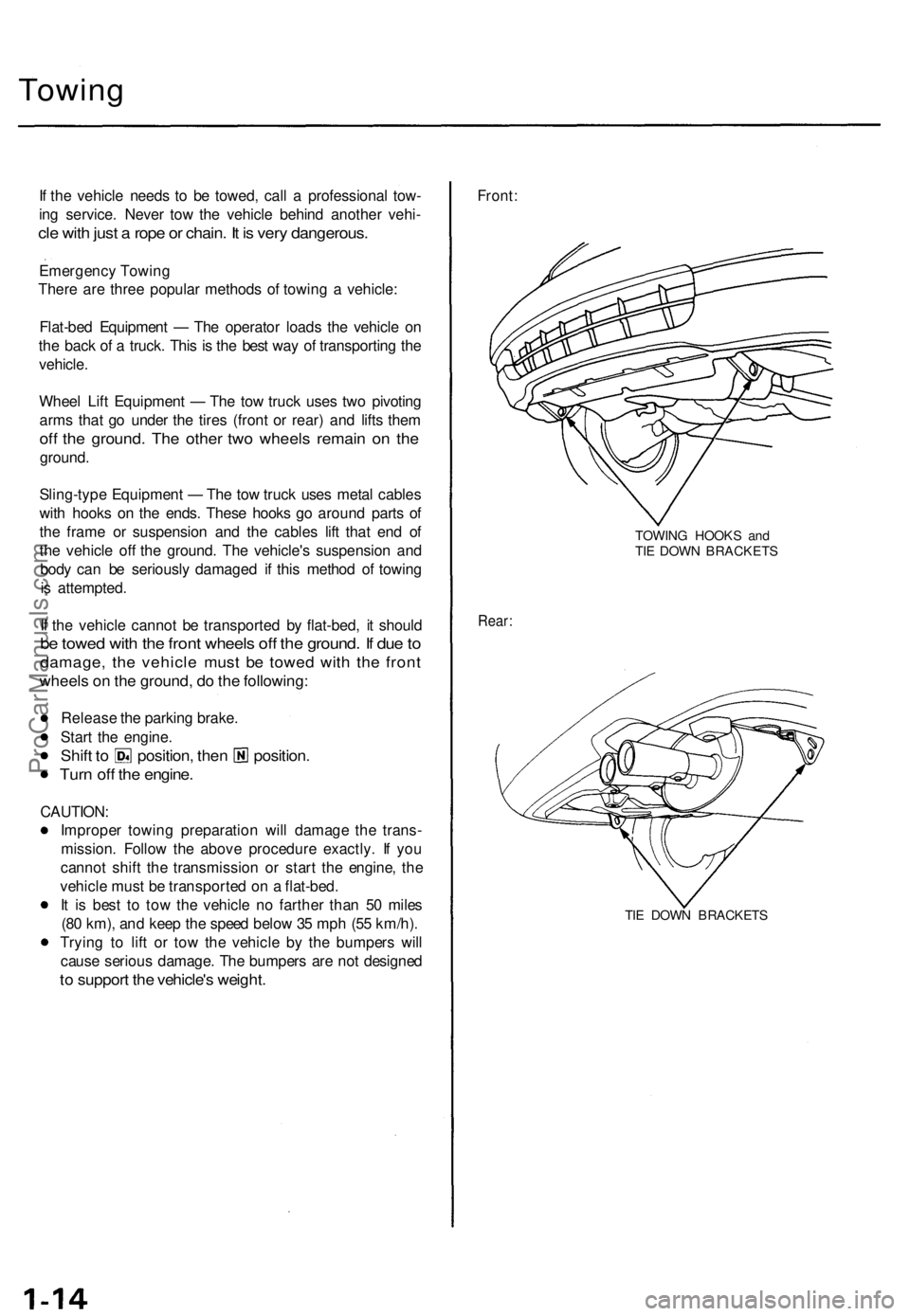
Front:
TOWING HOOKS and
TIE DOWN BRACKETS
Rear:
TIE DOWN BRACKETSProCarManuals.com
Page 492 of 1771
Component Location s Whee
l Alignmen t
Index
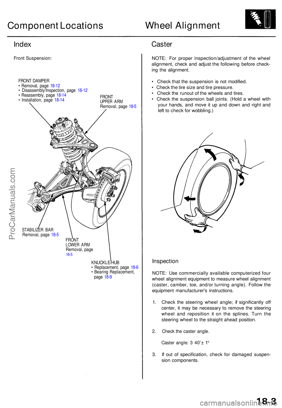
Fron t Suspension :
FRONT DAMPE R
• Removal , pag e 18-1 2
• Disassembly/Inspection , pag e 18-1 2
• Reassembly , pag e 18-1 4
• Installation , pag e 18-1 4 FRON
T
UPPER AR MRemoval , pag e 18- 5
STABILIZE R BA RRemoval , pag e 18- 5
FRON TLOWE R AR MRemoval , pag e18-5
KNUCKLE/HU B
• Replacement , pag e 18- 6
• Bearin g Replacement ,
pag e 18- 9
Caste r
NOTE : Fo r prope r inspection/adjustmen t of the whee l
alignment , chec k an d adjus t th e followin g befor e check -
in g th e alignment .
• Chec k tha t th e suspensio n i s no t modified .
• Chec k th e tir e siz e an d tir e pressure .
• Chec k th e runou t o f th e wheel s an d tires .
• Chec k th e suspensio n bal l joints . (Hol d a whee l wit h
you r hands , an d mov e i t u p an d dow n an d righ t an d
lef t t o chec k fo r wobbling. )
Inspection
NOTE: Us e commerciall y availabl e computerize d fou r
whee l alignmen t equipmen t t o measur e whee l alignmen t
(caster , camber , toe , and/o r turnin g angle) . Follo w th e
equipmen t manufacturer' s instructions .
1 . Chec k th e steerin g whee l angle ; i f significantl y of f
center , i t ma y b e necessar y t o remov e th e steerin g
whee l an d repositio n i t o n th e splines . Tur n th e
steerin g whee l t o th e straigh t ahea d position .
2. Chec k th e caste r angle .
Caster angle : 3 40' ± 1 °
3. I f ou t o f specification , chec k fo r damage d suspen -
sio n components .
ProCarManuals.com
Page 671 of 1771
General Info
Specifications
Maintenance
Engine
Cooling
Fuel and Emissions
2.5L
3.2L
* Transaxle
SteeringSuspension
* Brakes (Including ABS)
* Body
* Heating, Ventilation
and Air Conditioning
* Body Electrical
* Engine Electrical
* SRS2.5L
3.2L
1995±98 TL Main Menu
As sections w/ * include SRS components, special precautions are required when servicing.
ProCarManuals.com
Page 688 of 1771
Towing
If the vehicle needs to be towed, call a professional tow-
ing service. Never tow the vehicle behind another vehi-
cle with just a rope or chain. It is very dangerous.
Emergency Towing
There are three popular methods of towing a vehicle:
Flat-bed Equipment — The operator loads the vehicle on
the back of a truck. This is the best way of transporting the
vehicle.
Wheel Lift Equipment — The tow truck uses two pivoting
arms that go under the tires (front or rear) and lifts them
off the ground. The other two wheels remain on the
ground.
Sling-type Equipment — The tow truck uses metal cables
with hooks on the ends. These hooks go around parts of
the frame or suspension and the cables lift that end of
the vehicle off the ground. The vehicle's suspension and
body can be seriously damaged if this method of towing
is attempted.
If the vehicle cannot be transported by flat-bed, it should
be towed with the front wheels off the ground. If due to
damage, the vehicle must be towed with the front
wheels on the ground, do the following:
• Release the parking brake.
• Start the engine.
• Shift to position, then position.
• Turn off the engine.
CAUTION:
• Improper towing preparation will damage the trans-
mission. Follow the above procedure exactly. If you
cannot shift the transmission or start the engine, the
vehicle must be transported on a flat-bed.
• It is best to tow the vehicle no farther than 50 miles
(80 km), and keep the speed below 35 mph (55
km/h).
• Trying to lift or tow the vehicle by the bumpers will
cause serious damage. The bumpers are not
designed to support the vehicle's weight.
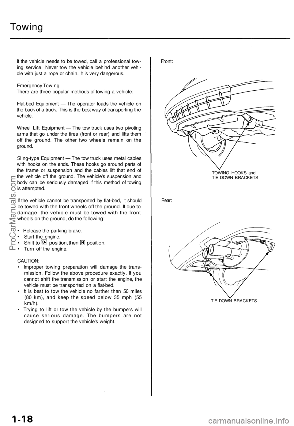
Front:
TOWING HOOKS and
TIE DOWN BRACKETS
Rear:
TIE DOWN BRACKETSProCarManuals.com
Page 1222 of 1771
Front Suspension
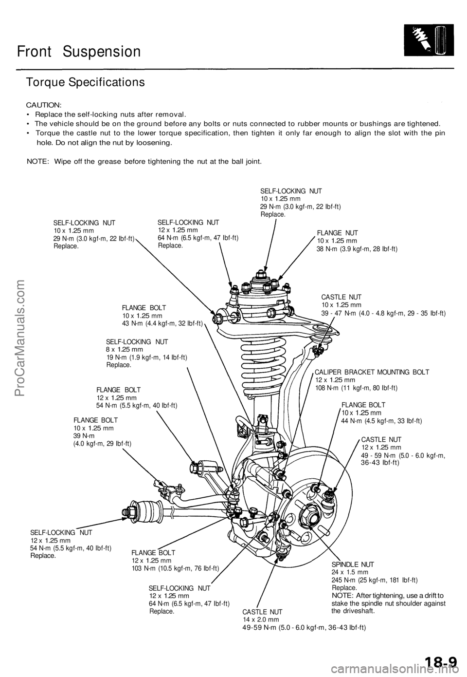
Torque Specifications
CAUTION:
• Replace the self-locking nuts after removal.
• The vehicle should be on the ground before any bolts or nuts connected to rubber mounts or bushings are tightened.
• Torque the castle nut to the lower torque specification, then tighten it only far enough to align the slot with the pin
hole. Do not align the nut by loosening.
NOTE: Wipe off the grease before tightening the nut at the ball joint.
SELF-LOCKING NUT
10 x
1.25
mm
29 N-m (3.0 kgf-m, 22 Ibf-ft)
Replace.
SELF-LOCKING NUT
12 x
1.25
mm
64 N-m (6.5 kgf-m, 47 Ibf-ft)
Replace.
SELF-LOCKING NUT
10 x
1.25
mm
29 N-m (3.0 kgf-m, 22 Ibf-ft)
Replace.
FLANGE BOLT
10 x
1.25
mm
43 N-m (4.4 kgf-m, 32 Ibf-ft)
SELF-LOCKING NUT
8 x
1.25
mm
19 N-m (1.9 kgf-m, 14 Ibf-ft)
Replace.
FLANGE BOLT
12 x
1.25
mm
54 N-m (5.5 kgf-m, 40 Ibf-ft)
FLANGE BOLT
10 x
1.25
mm
39 N-m
(4.0 kgf-m, 29 Ibf-ft)
SELF-LOCKING NUT
12 x
1.25
mm
54 N-m (5.5 kgf-m, 40 Ibf-ft)
Replace.
FLANGE NUT
10 x
1.25
mm
38 N-m (3.9 kgf-m, 28 Ibf-ft)
CASTLE NUT
10 x
1.25
mm
39 - 47 N-m (4.0 - 4.8 kgf-m, 29 - 35 Ibf-ft)
CALIPER BRACKET MOUNTING BOLT
12 x
1.25
mm
108 N-m (11 kgf-m, 80 Ibf-ft)
FLANGE BOLT
10 x
1.25
mm
44 N-m (4.5 kgf-m, 33 Ibf-ft)
CASTLE NUT
12 x
1.25
mm
49 - 59 N-m (5.0 - 6.0 kgf-m,
36-43 Ibf-ft)
FLANGE BOLT
12 x
1.25
mm
103 N-m (10.5 kgf-m, 76 Ibf-ft)
SELF-LOCKING NUT
12 x
1.25
mm
64 N-m (6.5 kgf-m, 47 Ibf-ft)
Replace.
CASTLE NUT
14 x 2.0 mm
49-59 N-m (5.0 - 6.0 kgf-m, 36-43 Ibf-ft)
SPINDLE NUT
24 x 1.5 mm
245 N-m (25 kgf-m, 181 Ibf-ft)
Replace.
NOTE: After tightening, use a drift to
stake the spindle nut shoulder against
the driveshaft.ProCarManuals.com
Page 1231 of 1771
Front Suspensio n
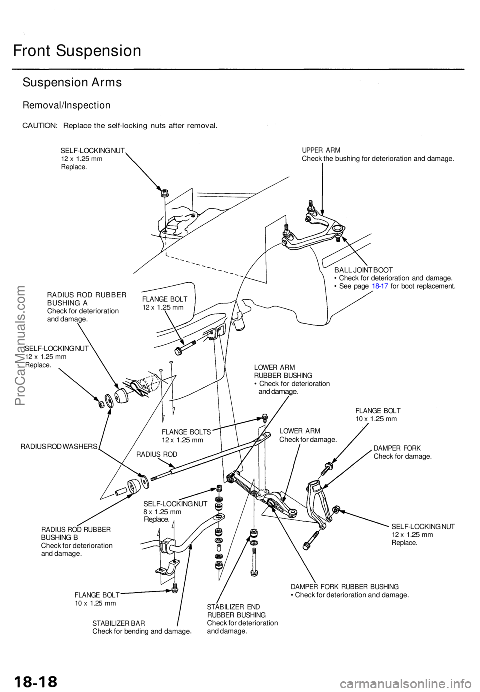
Suspension Arm s
Removal/Inspectio n
CAUTION: Replac e th e self-lockin g nut s afte r removal .
SELF-LOCKIN G NU T12 x 1.2 5 mmReplace .
UPPER AR MChec k th e bushin g fo r deterioratio n an d damage .
RADIU S RO D RUBBE R
BUSHIN G A
Chec k fo r deterioratio n
an d damage .
SELF-LOCKIN G NU T
12 x 1.2 5 mmReplace .
RADIUS RO D WASHER S BAL
L JOIN T BOO T
• Chec k fo r deterioratio n an d damage .
• Se e pag e 18-1 7 fo r boo t replacement .
FLANGE BOL T10 x 1.2 5 mm
DAMPE R FOR KCheck fo r damage .
RADIUS RO D RUBBE RBUSHING B
Chec k fo r deterioratio n
an d damage .
FLANGE BOL T10 x 1.2 5 mm
SELF-LOCKIN G NU T12 x 1.2 5 mmReplace .
DAMPER FOR K RUBBE R BUSHIN G• Chec k fo r deterioratio n an d damage .
STABILIZE R BA RChec k fo r bendin g an d damag e
STABILIZE R EN DRUBBE R BUSHIN GCheck fo r deterioratio n
an d damage .
SELF-LOCKIN
G NU T
8 x 1.2 5 mmReplace .
RADIUS RO D
FLANG E BOLT S12 x 1.2 5 mm
LOWE R AR MChec k fo r damage .
LOWER AR MRUBBE R BUSHIN G• Chec k fo r deterioratio nand damage .
FLANGE BOL T12 x 1.2 5 mm
ProCarManuals.com
Page 1241 of 1771
Rear Suspensio n
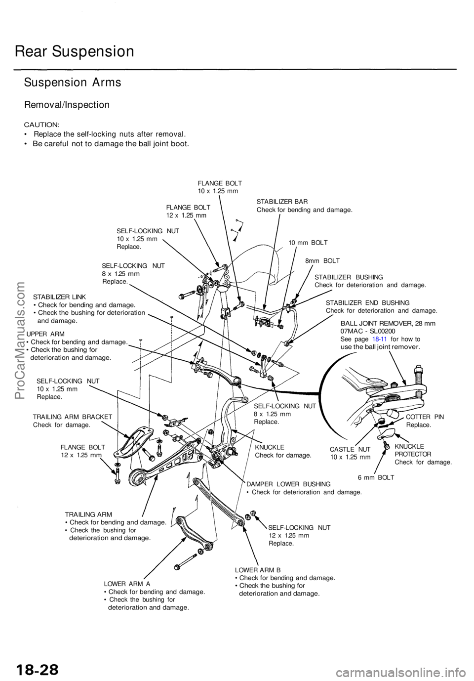
Suspension Arm s
Removal/Inspectio n
CAUTION:
• Replac e th e self-lockin g nut s afte r removal .
• B e carefu l no t t o damag e th e bal l join t boot .
FLANG E BOL T10 x 1.2 5 mm
FLANG E BOL T12 x 1.2 5 mm
SELF-LOCKIN G NU T10 x 1.2 5 mmReplace .
SELF-LOCKIN G NU T
8 x 1.2 5 mmReplace .
STABILIZE R BA RChec k fo r bendin g an d damage .
10 m m BOL T
8m m BOL T
STABILIZE R LIN K• Chec k fo r bendin g an d damage .• Chec k th e bushin g fo r deterioratio nand damage .
UPPER AR M• Chec k fo r bendin g an d damage .• Chec k th e bushin g fo rdeterioratio n an d damage .
SELF-LOCKIN G NU T10 x 1.2 5 mmReplace .
TRAILIN G AR M BRACKE T
Chec k fo r damage .
FLANG E BOL T
12 x 1.2 5 mm
STABILIZE R EN D BUSHIN G
Chec k fo r deterioratio n an d damage .
BALL JOIN T REMOVER , 2 8 m m07MA C - SL0020 0See pag e 18-1 1 fo r ho w tous e th e bal l join t remover .
CASTLE NU T10 x 1.2 5 mm
COTTE R PI N
Replace .
KNUCKL E
PROTECTO R
Chec k fo r damage .
TRAILING AR M• Chec k fo r bendin g an d damage .• Chec k th e bushin g fo rdeterioratio n an d damage .
LOWER AR M A• Chec k fo r bendin g an d damage .• Chec k th e bushin g fo rdeterioratio n an d damage .
6 m m BOL T
DAMPE R LOWE R BUSHIN G
• Chec k fo r deterioratio n an d damage .
SELF-LOCKIN G NU T
12 x 1.2 5 mmReplace .
LOWER AR M B• Chec k fo r bendin g an d damage .• Chec k th e bushin g fo rdeterioratio n an d damage .
KNUCKL ECheck fo r damage .
SELF-LOCKIN G NU T8 x 1.2 5 mmReplace . STABILIZE
R BUSHIN G
Chec k fo r deterioratio n an d damage .
ProCarManuals.com
Page 1247 of 1771
Rear Dampe r
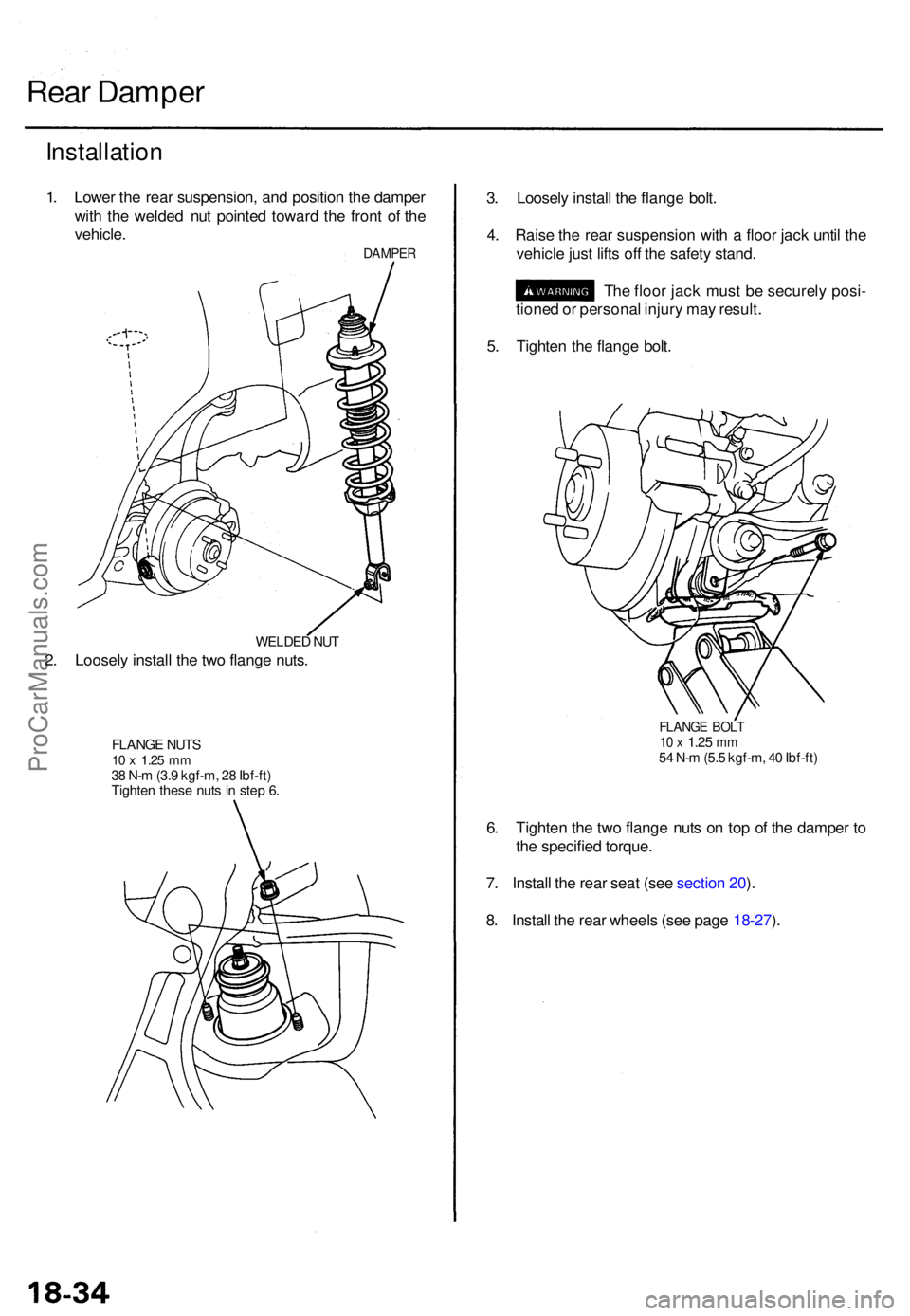
Installatio n
1. Lowe r th e rea r suspension , an d positio n th e dampe r
wit h th e welde d nu t pointe d towar d th e fron t o f th e
vehicle .
DAMPE R
WELDED NU T
2. Loosel y instal l th e tw o flang e nuts .
FLANG E NUT S10 x 1.2 5 mm38 N- m (3. 9 kgf-m , 2 8 Ibf-ft )
Tighte n thes e nut s i n ste p 6 .
3. Loosel y instal l th e flang e bolt .
4 . Rais e th e rea r suspensio n wit h a floo r jac k unti l th e
vehicl e jus t lift s of f th e safet y stand .
Th e floo r jac k mus t b e securel y posi -
tione d o r persona l injur y ma y result .
5 . Tighte n th e flang e bolt .
FLANG E BOL T10 x 1.2 5 mm54 N- m (5. 5 kgf-m , 4 0 Ibf-ft )
6. Tighte n th e tw o flang e nut s o n to p o f th e dampe r t o
th e specifie d torque .
7 . Instal l th e rea r sea t (se e sectio n 20 ).
8 . Instal l th e rea r wheel s (se e pag e 18-27 ).
ProCarManuals.com