wheel alignment ACURA TL 1995 Service Repair Manual
[x] Cancel search | Manufacturer: ACURA, Model Year: 1995, Model line: TL, Model: ACURA TL 1995Pages: 1771, PDF Size: 62.49 MB
Page 492 of 1771

Component Location s Whee
l Alignmen t
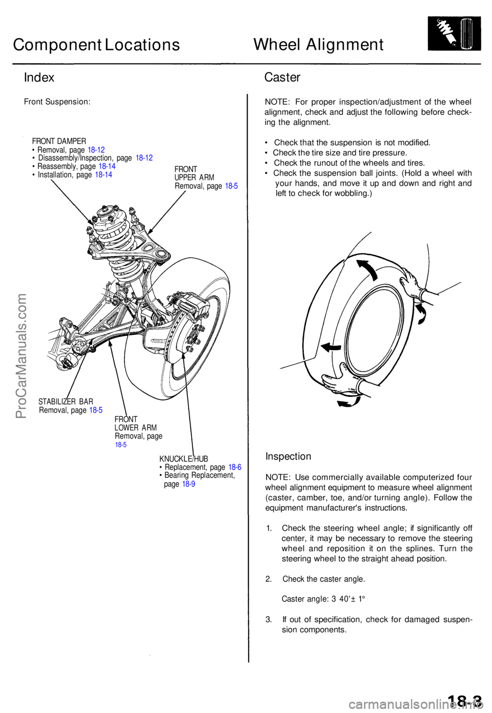
Index
Fron t Suspension :
FRONT DAMPE R
• Removal , pag e 18-1 2
• Disassembly/Inspection , pag e 18-1 2
• Reassembly , pag e 18-1 4
• Installation , pag e 18-1 4 FRON
T
UPPER AR MRemoval , pag e 18- 5
STABILIZE R BA RRemoval , pag e 18- 5
FRON TLOWE R AR MRemoval , pag e18-5
KNUCKLE/HU B
• Replacement , pag e 18- 6
• Bearin g Replacement ,
pag e 18- 9
Caste r
NOTE : Fo r prope r inspection/adjustmen t of the whee l
alignment , chec k an d adjus t th e followin g befor e check -
in g th e alignment .
• Chec k tha t th e suspensio n i s no t modified .
• Chec k th e tir e siz e an d tir e pressure .
• Chec k th e runou t o f th e wheel s an d tires .
• Chec k th e suspensio n bal l joints . (Hol d a whee l wit h
you r hands , an d mov e i t u p an d dow n an d righ t an d
lef t t o chec k fo r wobbling. )
Inspection
NOTE: Us e commerciall y availabl e computerize d fou r
whee l alignmen t equipmen t t o measur e whee l alignmen t
(caster , camber , toe , and/o r turnin g angle) . Follo w th e
equipmen t manufacturer' s instructions .
1 . Chec k th e steerin g whee l angle ; i f significantl y of f
center , i t ma y b e necessar y t o remov e th e steerin g
whee l an d repositio n i t o n th e splines . Tur n th e
steerin g whee l t o th e straigh t ahea d position .
2. Chec k th e caste r angle .
Caster angle : 3 40' ± 1 °
3. I f ou t o f specification , chec k fo r damage d suspen -
sio n components .
ProCarManuals.com
Page 1218 of 1771

Wheel Alignmen t
Caster
NOTE : Fo r prope r inspection/adjustmen t o f th e whee l
alignment , chec k an d adjus t th e followin g befor e check -
ing th e alignment .
• Chec k tha t th e suspensio n i s no t modified .
• Chec k th e tir e siz e an d tir e pressure .
• Chec k th e runou t o f th e wheel s an d tires .
• Chec k th e suspensio n bal l joints . (Hol d th e whee l wit h
you r hands , the n mov e i t u p an d down , an d righ t an d
lef t t o chec k fo r wobbling. )
Inspection
NOTE: Us e commercially-availabl e computerize d fou r
whee l alignmen t equipmen t t o measur e whee l align -
men t (caster , camber , toe , and/o r turnin g angle) .
Follo w th e equipmen t manufacturer' s instructions .
1 . Chec k th e caste r angle .
Caste r angle : 2°07 ' ± 1 °
2 . I f ou t o f specification , recor d th e caste r reading , the n
adjus t th e caster .
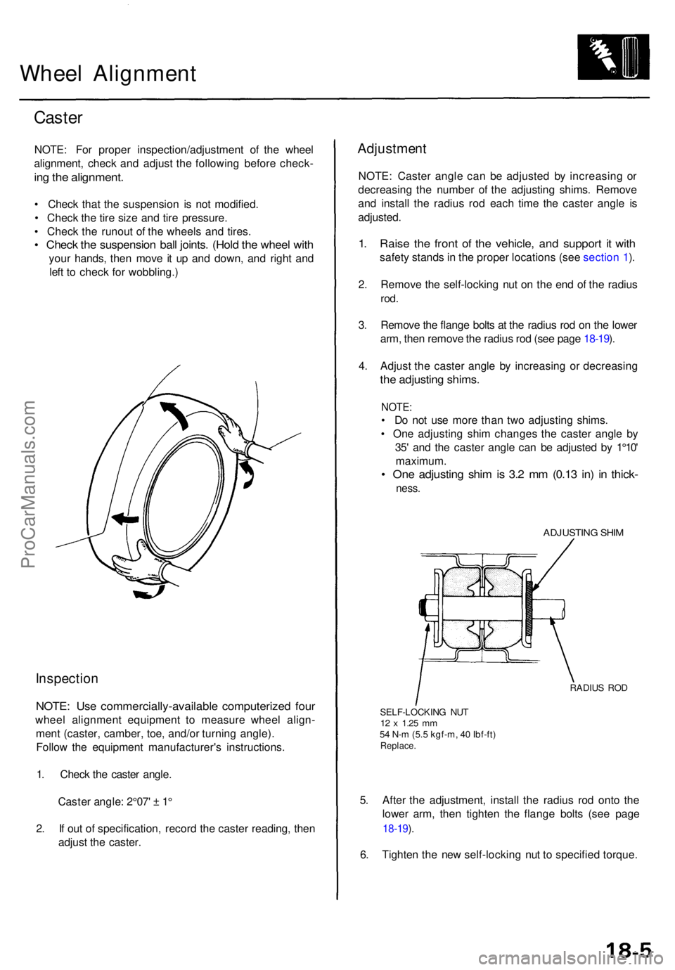
Adjustmen t
NOTE: Caste r angl e ca n b e adjuste d b y increasin g o r
decreasin g th e numbe r o f th e adjustin g shims . Remov e
an d instal l th e radiu s ro d eac h tim e th e caste r angl e i s
adjusted .
1. Rais e th e fron t o f th e vehicle , an d suppor t i t wit h
safet y stand s in th e prope r location s (se e sectio n 1 ).
2 . Remov e th e self-lockin g nu t o n th e en d o f th e radiu s
rod.
3. Remov e th e flang e bolt s a t th e radiu s ro d o n th e lowe r
arm , the n remov e th e radiu s ro d (se e pag e 18-19 ).
4 . Adjus t th e caste r angl e b y increasin g o r decreasin g
the adjustin g shims .
NOTE:
• D o no t us e mor e tha n tw o adjustin g shims .
• On e adjustin g shi m change s th e caste r angl e b y
35 ' an d th e caste r angl e ca n b e adjuste d b y 1°10 '
maximum .
• On e adjustin g shi m is 3. 2 m m (0.1 3 in ) i n thick -
ness.
ADJUSTIN G SHI M
RADIU S RO D
SELF-LOCKIN G NU T
12 x 1.2 5 mm54 N- m (5. 5 kgf-m , 4 0 Ibf-ft )Replace .
5. Afte r th e adjustment , instal l th e radiu s ro d ont o th e
lowe r arm , the n tighte n th e flang e bolt s (se e pag e
18-19 ).
6 . Tighte n th e ne w self-lockin g nu t t o specifie d torque .
ProCarManuals.com