wheel bolts ACURA TL 1995 Service Repair Manual
[x] Cancel search | Manufacturer: ACURA, Model Year: 1995, Model line: TL, Model: ACURA TL 1995Pages: 1771, PDF Size: 62.49 MB
Page 317 of 1771
A/T Gea r Positio n Switc h
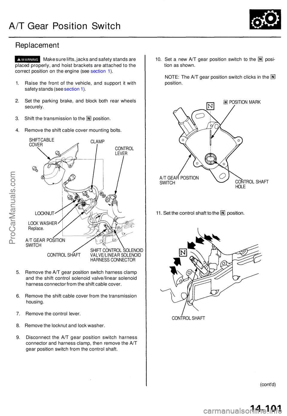
Replacemen t
Make sur e lifts , jack s an d safet y stand s ar e
place d properly , an d hois t bracket s ar e attache d to th e
correc t positio n o n th e engin e (se e sectio n 1 ).
1 . Rais e th e fron t o f th e vehicle , an d suppor t i t wit h
safet y stand s (se e sectio n 1 ).
2 . Se t th e parkin g brake , an d bloc k bot h rea r wheel s
securely .
3. Shif t th e transmissio n t o th e position .
4 . Remov e th e shif t cabl e cove r mountin g bolts .
CLAM P
SHIF
T CABL ECOVERCONTRO LLEVER
CONTRO L SHAF T SHIF
T CONTRO L SOLENOI DVALVE/LINEA R SOLENOI DHARNESS CONNECTO R
5. Remov e th e A/ T gea r positio n switc h harnes s clam p
an d th e shif t contro l solenoi d valve/linea r solenoi d
harnes s connecto r fro m th e shif t cabl e cover .
6 . Remov e th e shif t cabl e cove r fro m th e transmissio n
housing .
7 . Remov e th e contro l lever .
8 . Remov e th e locknu t an d loc k washer .
9 . Disconnec t th e A/ T gea r positio n switc h harnes s
connecto r an d harnes s clamp , the n remov e th e A/ T
gea r positio n switc h fro m th e contro l shaft .
10. Se t a ne w A/ T gea r positio n switc h t o th e posi -
tio n a s shown .
NOTE: Th e A/ T gea r positio n switc h click s in th e
position .
POSITIO N MAR K
A/ T GEA R POSITIO N
SWITC H CONTRO
L SHAF T
HOL E
11. Se t th e contro l shaf t t o th e position .
CONTROL SHAF T
(cont'd )
LOCKNU T
LOCK WASHE RReplace.
A/T GEA R POSITIO N
SWITC H
ProCarManuals.com
Page 336 of 1771
Lower Valv e Bod y Assembl y
Removal/Installatio n
Make sur e lifts , jack s an d safet y stand s ar e
place d properly , an d hois t bracket s ar e attache d to th e
correc t positio n o n th e engin e (se e sectio n 1 ).
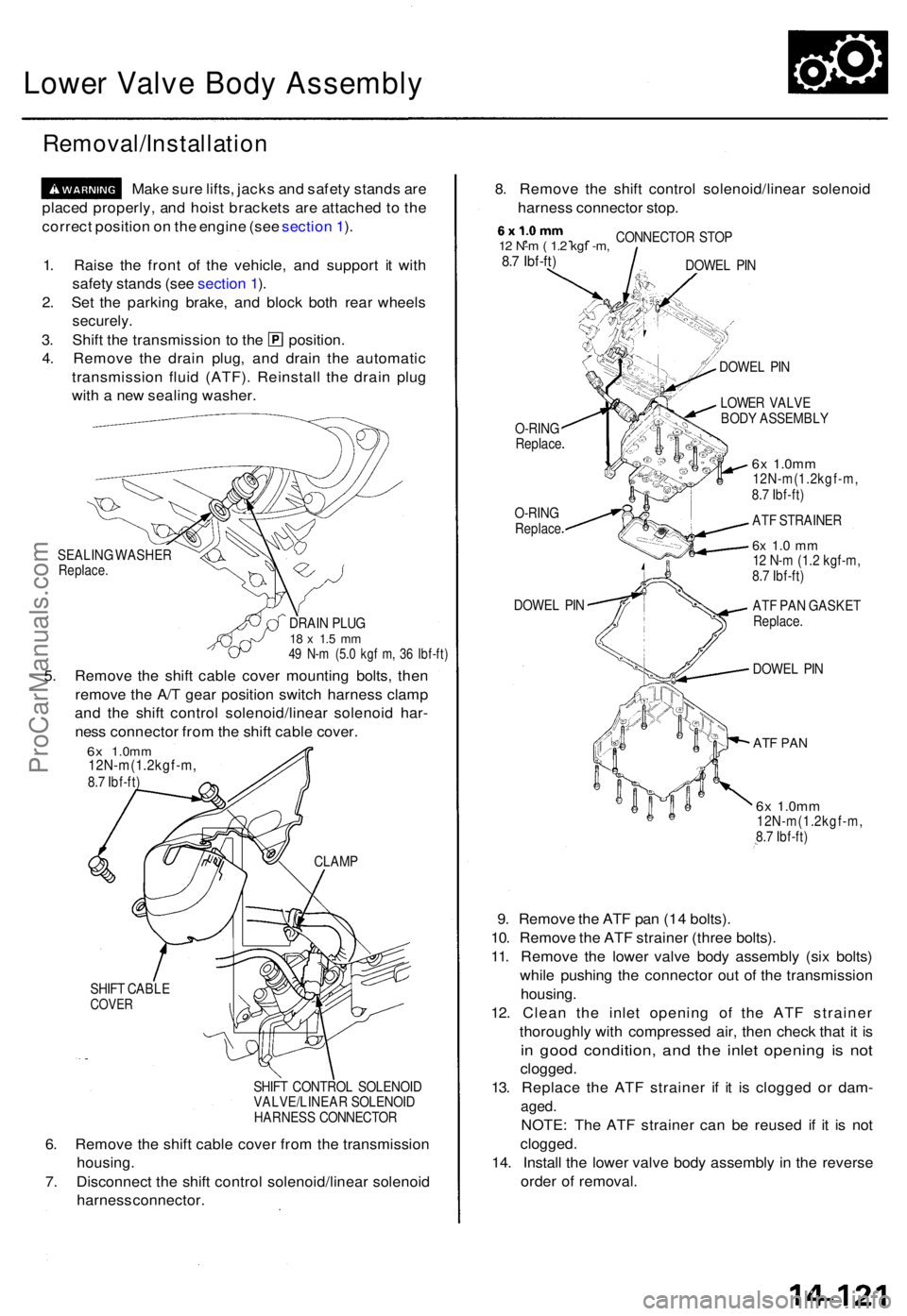
SEALIN G WASHE RReplace.
DRAIN PLU G18 x 1. 5 m m49 N- m (5. 0 kg f m , 3 6 Ibf-ft )
5. Remov e th e shif t cabl e cove r mountin g bolts , the n
remov e th e A/ T gea r positio n switc h harnes s clam p
an d th e shif t contro l solenoid/linea r solenoi d har -
nes s connecto r fro m th e shif t cabl e cover .
6x 1.0m m12N-m(1.2kgf-m ,8.7 Ibf-ft )
SHIF T CABL E
COVER
SHIFT CONTRO L SOLENOI D
VALVE/LINEA R SOLENOI D
HARNES S CONNECTO R
6. Remov e th e shif t cabl e cove r fro m th e transmissio n
housing.
7. Disconnec t th e shif t contro l solenoid/linea r solenoi d
harnes s connector . 8
. Remov e th e shif t contro l solenoid/linea r solenoi d
harnes s connecto r stop .
, . .12 N- m ( 1. 2 kg f -m ,8.7 Ibf-ft )
CONNECTO R STO P
DOWE L PI N
O-RIN G
Replac e
O-RINGReplac e
DOWEL PI N DOWE
L PI N
LOWE R VALV E
BOD Y ASSEMBL Y
6x 1.0m m12N-m(1.2kgf-m ,
8. 7 Ibf-ft )
AT F STRAINE R
6x 1. 0 m m12 N- m (1.2 kgf-m ,
8. 7 Ibf-ft )
AT F PA N GASKE T
Replace .
DOWEL PI N
AT F PA N
6x 1.0m m12N-m(1.2kgf-m ,
8. 7 Ibf-ft )
9. Remov e th e AT F pa n (1 4 bolts) .
10 . Remov e th e AT F straine r (thre e bolts) .
11 . Remov e th e lowe r valv e bod y assembl y (si x bolts )
whil e pushin g th e connecto r ou t o f th e transmissio n
housing .
12 . Clea n th e inle t openin g o f th e AT F straine r
thoroughl y wit h compresse d air , the n chec k tha t i t i s
in goo d condition , an d th e inle t openin g i s no t
clogged .
13. Replac e th e AT F straine r i f i t i s clogge d o r dam -
aged.
NOTE : Th e AT F straine r ca n b e reuse d i f i t i s no t
clogged .
14 . Instal l th e lowe r valv e bod y assembly in th e revers e
orde r o f removal .
1
. Rais e th e fron t o f th e vehicle , an d suppor t i t wit h
safet y stand s (se e sectio n 1 ).
2 . Se t th e parkin g brake , an d bloc k bot h rea r wheel s
securely .
3. Shif t th e transmissio n t o th e position .
4 . Remov e th e drai n plug , an d drai n th e automati c
transmissio n flui d (ATF) . Reinstal l th e drai n plu g
wit h a ne w sealin g washer .
CLAMP
ProCarManuals.com
Page 435 of 1771
Differential Assembl y
Removal
• Mak e sur e jack s an d safet y stand s ar e place d properly ,
an d hois t bracket s ar e attache d to correc t position s o n
th e engine .
• Appl y parkin g brak e an d bloc k rea r wheel s s o th e
vehicl e wil l no t rol l of f stand s an d fal l o n yo u whil e
workin g unde r it .
CAUTION : Us e fende r cover s t o avoi d damagin g painte d
surfaces .
1. Remov e th e drai n plug , an d drai n th e differentia l oi l
(se e pag e 15-4 ).
2 . Remov e th e driveshaft s an d intermediat e shaf t (se e
sectio n 16 ).
3 . Remov e th e 3 6 m m sealin g bolt , the n disconnec t
th e extensio n shaf t fro m th e differentia l usin g th e
specia l tool .
NOTE : Shif t th e transmissio n int o th e positio n t o
loc k th e secondar y gear .
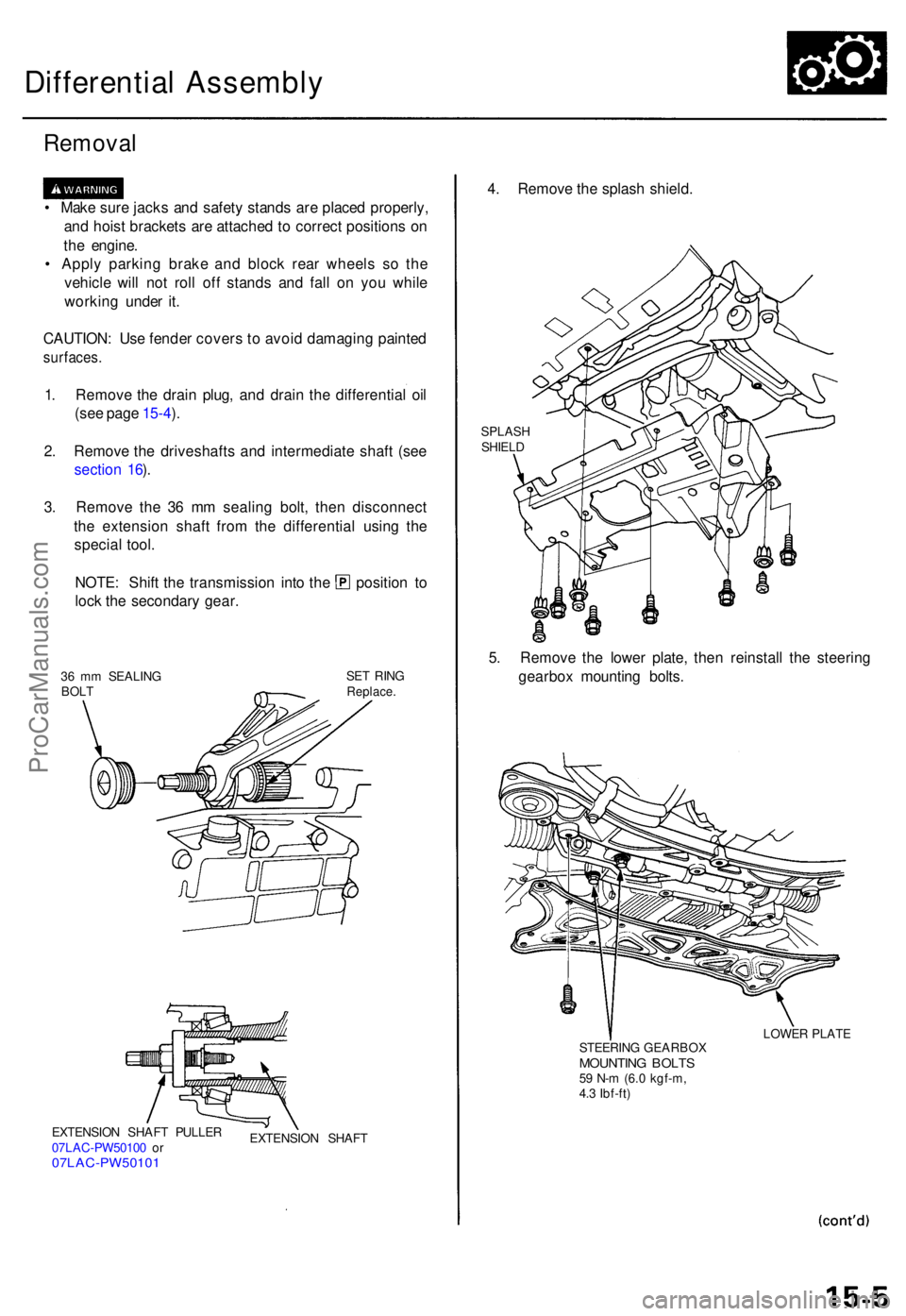
36 m m SEALIN G
BOL T SE
T RIN GReplace .
EXTENSIO N SHAF T PULLE R
07LA C-PW5010 0 o r
07LAC-PW5010 1
EXTENSION SHAF T
4. Remov e th e splas h shield .
SPLAS H
SHIEL D
5. Remov e th e lowe r plate , the n reinstal l th e steerin g
gearbo x mountin g bolts .
STEERIN G GEARBO XMOUNTING BOLT S59 N- m (6. 0 kgf-m ,
4. 3 Ibf-ft ) LOWE
R PLAT E
ProCarManuals.com
Page 473 of 1771
Steering Gearbo x
Remova l
NOTE: Us e solven t an d a brus h t o was h of f an y oi l an d
dir t fro m th e valv e bod y unit , it s lines , an d th e en d o f
th e gearbox . Blo w dr y wit h compresse d air .
1 . Drai n th e powe r steerin g flui d (refe r t o th e '9 5 - 9 8
Acur a 2.5T L Servic e Manual , P/ N 61SW504) .
2 . Rais e th e fron t o f vehicle , an d suppor t i t o n safet y
stand s in th e prope r locations .
3 . Remov e th e fron t wheels .
4 . Remov e th e driver' s airba g assembl y an d steerin g
whee l (refe r t o th e '9 5 - 9 8 Acur a 2.5T L Servic e
Manual , P/ N 61SW504) :
5 . Remov e th e cotte r pi n fro m th e castl e nut , an d
remov e th e nut .
6 . Instal l th e 1 2 m m he x nu t o n th e bal l joint . B e sur e
tha t th e 1 2 m m he x nu t i s flus h wit h th e bal l join t
pi n end , o r th e threade d sectio n o f th e bal l join t pi n
migh t b e damage d b y th e specia l tool .
NOTE : Remov e th e bal l join t usin g th e Bal l Join t
Remover , 2 8 m m (07MA C - SL00200) . Refe r t o pag e
18- 8 fo r ho w to us e th e bal l join t remover .
7 . Separat e th e tie-ro d bal l join t an d knuckl e usin g th e
specia l tool .
CAUTION : Avoi d damagin g th e bal l join t boot .
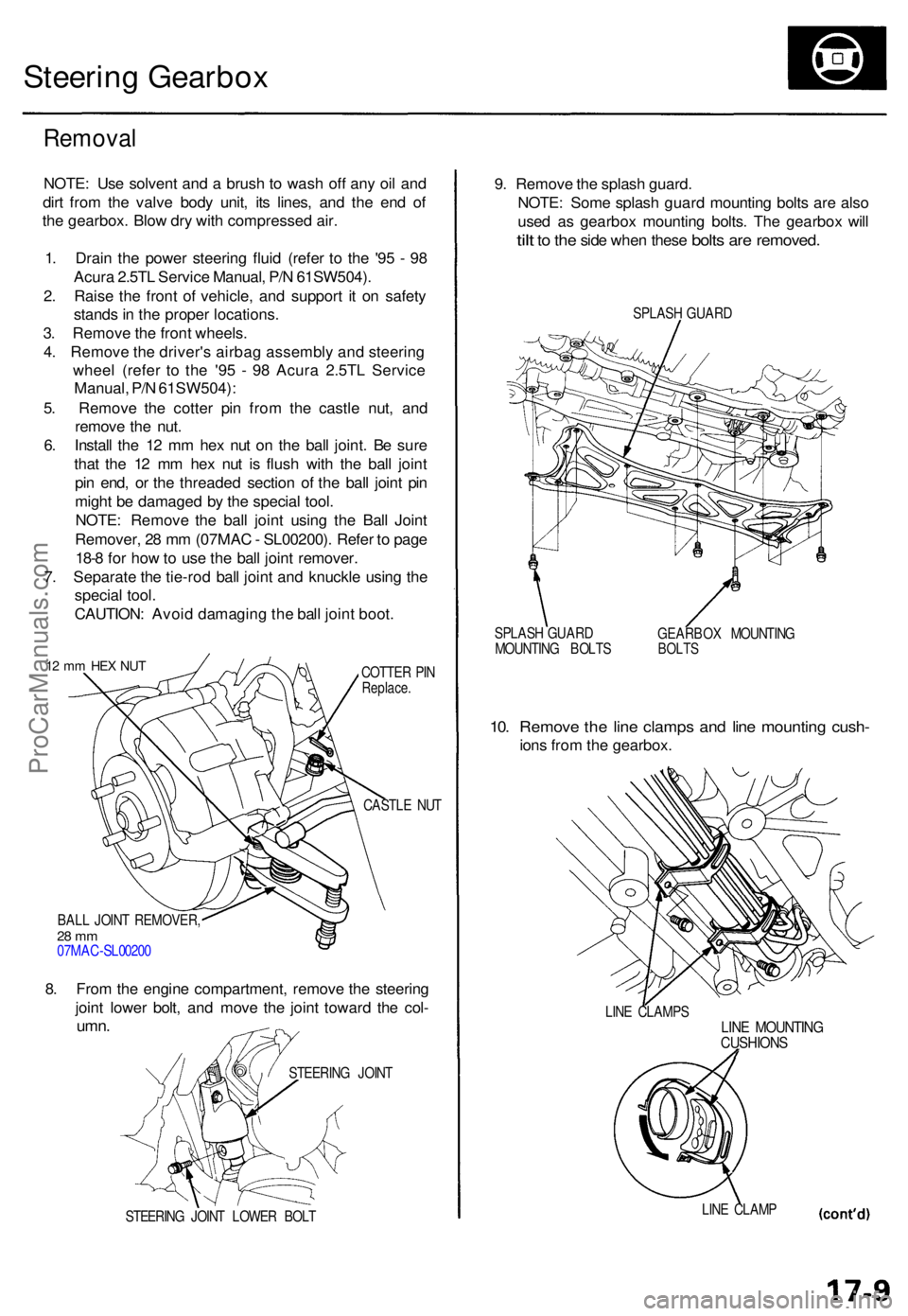
12 m m HE X NU TCOTTE R PI NReplace .
CASTLE NU T
BAL L JOIN T REMOVER ,
28 m m07MA C-SL0020 0
8. Fro m th e engin e compartment , remov e th e steerin g
join t lowe r bolt , an d mov e th e join t towar d th e col -
umn .
STEERIN G JOIN T LOWE R BOL T
9. Remov e th e splas h guard .
NOTE : Som e splas h guar d mountin g bolt s ar e als o
use d a s gearbo x mountin g bolts . Th e gearbo x wil l
tilt to th e sid e whe n thes e bolts are removed .
SPLASH GUAR D
SPLAS H GUAR D
MOUNTIN G BOLT S GEARBO
X MOUNTIN G
BOLTS
10. Remov e th e lin e clamp s an d lin e mountin g cush -
ions fro m th e gearbox .
LINE CLAMP SLINE MOUNTIN GCUSHIONS
LINE CLAM P
STEERIN
G JOIN T
ProCarManuals.com
Page 486 of 1771
Steering Gearbox
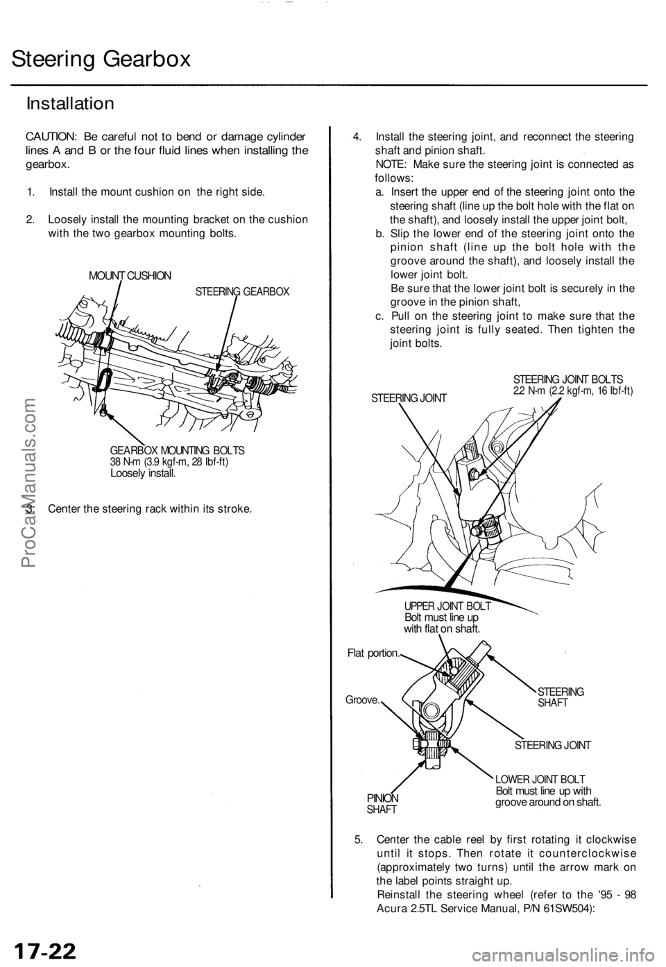
Installation
CAUTION: Be careful not to bend or damage cylinder
lines A and B or the four fluid lines when installing the
gearbox.
1. Install the mount cushion on the right side.
2. Loosely install the mounting bracket on the cushion
with the two gearbox mounting bolts.
MOUNT CUSHION
STEERING GEARBOX
GEARBOX MOUNTING BOLTS
38 N-m (3.9 kgf-m, 28 Ibf-ft)
Loosely install.
3. Center the steering rack within its stroke.
4. Install the steering joint, and reconnect the steering
shaft and pinion shaft.
NOTE: Make sure the steering joint is connected as
follows:
a. Insert the upper end of the steering joint onto the
steering shaft (line up the bolt hole with the flat on
the shaft), and loosely install the upper joint bolt,
b. Slip the lower end of the steering joint onto the
pinion shaft (line up the bolt hole with the
groove around the shaft), and loosely install the
lower joint bolt.
Be sure that the lower joint bolt is securely in the
groove in the pinion shaft,
c. Pull on the steering joint to make sure that the
steering joint is fully seated. Then tighten the
joint bolts.
STEERING JOINT
STEERING JOINT BOLTS
2.2 N-m (2.2 kgf-m, 16 Ibf-ft)
UPPER JOINT BOLT
Bolt must line up
with flat on shaft.
Flat portion.
Groove.
STEERING
SHAFT
PINION
SHAFT
STEERING JOINT
LOWER JOINT BOLT
Bolt must line up with
groove around on shaft.
5. Center the cable reel by first rotating it clockwise
until it stops. Then rotate it counterclockwise
(approximately two turns) until the arrow mark on
the label points straight up.
Reinstall the steering wheel (refer to the '95 - 98
Acura 2.5TL Service Manual, P/N 61SW504):ProCarManuals.com
Page 496 of 1771
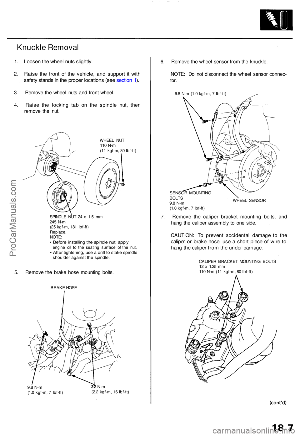
1. Loose n th e whee l nut s slightly .
2. Rais e th e fron t o f th e vehicle , an d suppor t i t wit h
safet y stand s in th e prope r location s (se e sectio n 1 ).
3 . Remov e th e whee l nut s an d fron t wheel .
4 . Rais e th e lockin g ta b o n th e spindl e nut , the n
remov e th e nut .
WHEE L NU T110 N- m(11 kgf-m , 8 0 Ibf-ft )
SPINDL E NU T 2 4 x 1. 5 m m
245 N- m(25 kgf-m , 18 1 Ibf-ft )
Replace .
NOTE :
• Befor e installin g th e spindl e nut , appl yengin e oi l t o th e seating surface o f th e nut .• Afte r tightening , us e a drif t t o stak e spindl eshoulde r agains t th e spindle .
5. Remov e th e brak e hos e mountin g bolts .
BRAK E HOS E
9.8 N- m(1.0 kgf-m , 7 Ibf-ft )
N-m(2. 2 kgf-m , 1 6 Ibf-ft )
6. Remov e th e whee l senso r fro m th e knuckle .
NOTE : D o no t disconnec t th e whee l senso r connec -
tor.
9.8 N- m (1. 0 kgf-m , 7 Ibf-ft )
SENSO R MOUNTIN GBOLTS9.8 N- m(1.0 kgf-m , 7 Ibf-ft ) WHEE
L SENSO R
7. Remov e th e calipe r bracke t mountin g bolts , an d
han g th e calipe r assembl y t o on e side .
CAUTION : T o preven t accidenta l damag e t o th e
calipe r o r brak e hose , us e a shor t piec e o f wir e t o
han g th e calipe r fro m th e under-carriage .
CALIPER BRACKE T MOUNTIN G BOLT S12 x 1.2 5 mm110 N- m (1 1 kgf-m , 8 0 Ibf-ft )
Knuckle Removal
ProCarManuals.com
Page 660 of 1771
Airbag
Replacement (cont'd)
CAUTION: Be sure to install the SRS wiring so that it is
not pinched or interfering with other parts.
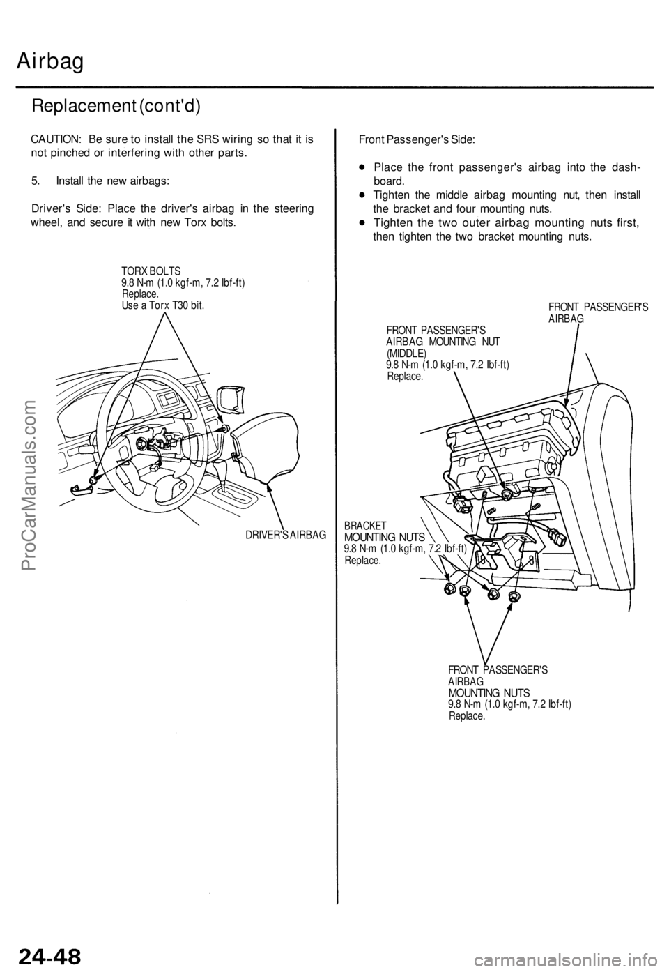
5. Install the new airbags:
Driver's Side: Place the driver's airbag in the steering
wheel, and secure it with new Torx bolts.
TORX BOLTS
9.8 N-m (1.0 kgf-m, 7.2 Ibf-ft)
Replace.
Use a Torx T30 bit.
DRIVER'S AIRBAG
Front Passenger's Side:
Place the front passenger's airbag into the dash-
board.
Tighten the middle airbag mounting nut, then install
the bracket and four mounting nuts.
Tighten the two outer airbag mounting nuts first,
then tighten the two bracket mounting nuts.
FRONT PASSENGER'S
AIRBAG
FRONT PASSENGER'S
AIRBAG MOUNTING NUT
(MIDDLE)
9.8 N-m (1.0 kgf-m, 7.2 Ibf-ft)
Replace.
BRACKET
MOUNTING NUTS
9.8 N-m (1.0 kgf-m, 7.2 Ibf-ft)
Replace.
FRONT PASSENGER'S
AIRBAG
MOUNTING NUTS
9.8 N-m (1.0 kgf-m, 7.2 Ibf-ft)
Replace.ProCarManuals.com
Page 664 of 1771
Cable Ree l
Replacemen t
Store a remove d airba g wit h th e pa d sur -
fac e up . I f th e airba g i s improperl y store d fac e down ,
accidenta l deploymen t coul d prope l th e uni t wit h
enoug h forc e to caus e seriou s injury .
CAUTION :
Alway s disconnec t th e airba g connecto r whe n th e
SR S mai n harnes s is disconnected .
D o no t disassembl e o r tampe r wit h th e airbag .
NOTE : Carefull y inspec t th e airba g befor e installin g it .
D o no t instal l a n airba g tha t show s sign s o f bein g
droppe d o r improperl y handled , suc h a s dents , crack s o r
deformation .
1 . Mak e sur e yo u hav e th e anti-thef t cod e fo r th e
radio , the n writ e dow n th e frequencie s fo r th e
radio' s prese t buttons .
2. Disconnec t th e batter y negativ e cable , the n discon -
nec t th e positiv e cabl e fro m th e battery , an d wai t a t
leas t thre e minutes .
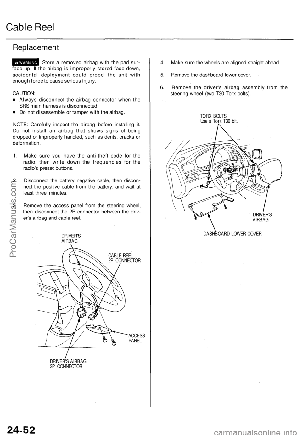
3 . Remov e th e acces s pane l fro m th e steerin g wheel ,
the n disconnec t th e 2 P connecto r betwee n th e driv -
er' s airba g an d cabl e reel .
DRIVER' SAIRBAG
CABLE REE L
2 P CONNECTO R
ACCESSPANEL
DRIVER' S AIRBA G
2 P CONNECTO R
4. Mak e sur e th e wheel s ar e aligne d straigh t ahead .
5 . Remov e th e dashboar d lowe r cover .
6 . Remov e th e driver' s airba g assembl y fro m th e
steerin g whee l (tw o T3 0 Tor x bolts) .
TORX BOLT S
Us e a Tor x T3 0 bit .
DRIVER' SAIRBAG
DASHBOAR D LOWE R COVE R
ProCarManuals.com
Page 667 of 1771
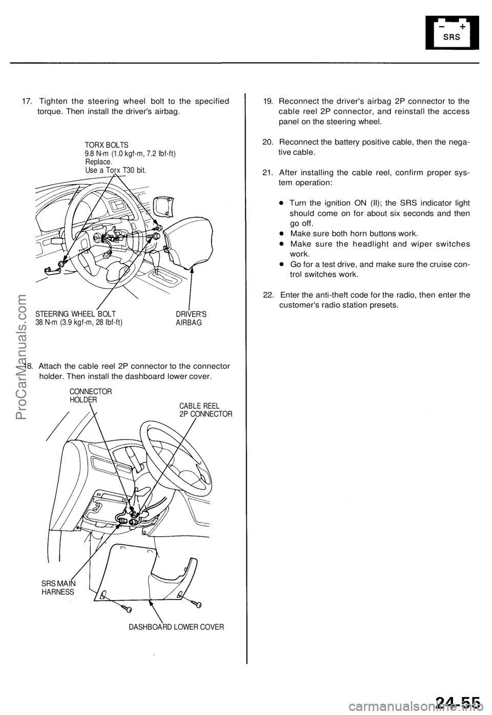
17. Tighten the steering wheel bolt to the specified
torque. Then install the driver's airbag.
TORX BOLTS
9.8 N-m (1.0 kgf-m, 7.2 Ibf-ft)
Replace.
Use a Torx T30 bit.
STEERING WHEEL BOLT
38 N-m (3.9 kgf-m, 28 Ibf-ft)
DRIVER'S
AIRBAG
18. Attach the cable reel 2P connector to the connector
holder. Then install the dashboard lower cover.
CONNECTOR
HOLDER
CABLE REEL
2P CONNECTOR
SRS
MAIN
HARNESS
DASHBOARD LOWER COVER
19. Reconnect the driver's airbag 2P connector to the
cable reel 2P connector, and reinstall the access
panel on the steering wheel.
20. Reconnect the battery positive cable, then the nega-
tive cable.
21. After installing the cable reel, confirm proper sys-
tem operation:
Turn the ignition ON (II); the SRS indicator light
should come on for about six seconds and then
go
off.
Make sure both horn buttons work.
Make sure the headlight and wiper switches
work.
Go for a test drive, and make sure the cruise con-
trol switches work.
22. Enter the anti-theft code for the radio, then enter the
customer's radio station presets.ProCarManuals.com
Page 669 of 1771
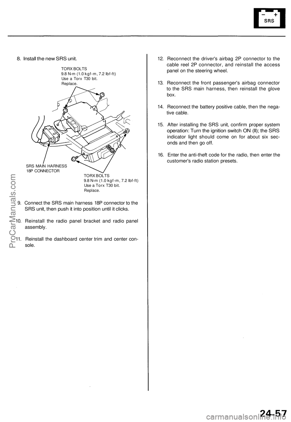
8. Install the new SRS unit.
TORX BOLTS
9.8 N-m (1.0 kgf-m, 7.2 Ibf-ft)
Use a Torx T30 bit.
Replace.
SRS MAIN HARNESS
18P CONNECTOR
TORX BOLTS
9.8 N-m (1.0 kgf-m, 7.2 Ibf-ft)
Use a Torx T30 bit.
Replace.
9. Connect the SRS main harness 18P connector to the
SRS unit, then push it into position until it clicks.
10. Reinstall the radio panel bracket and radio panel
assembly.
11. Reinstall the dashboard center trim and center con-
sole.
12. Reconnect the driver's airbag 2P connector to the
cable reel 2P connector, and reinstall the access
panel on the steering wheel.
13. Reconnect the front passenger's airbag connector
to the SRS main harness, then reinstall the glove
box.
14. Reconnect the battery positive cable, then the nega-
tive cable.
15. After installing the SRS unit, confirm proper system
operation: Turn the ignition switch ON (II); the SRS
indicator light should come on for about six sec-
onds and then go off.
16. Enter the anti-theft code for the radio, then enter the
customer's radio station presets.ProCarManuals.com