driver seat adjustment Alfa Romeo 147 2005 Owner handbook (in English)
[x] Cancel search | Manufacturer: ALFA ROMEO, Model Year: 2005, Model line: 147, Model: Alfa Romeo 147 2005Pages: 291, PDF Size: 5.52 MB
Page 19 of 291
GETTING TO KNOW YOUR CAR
17
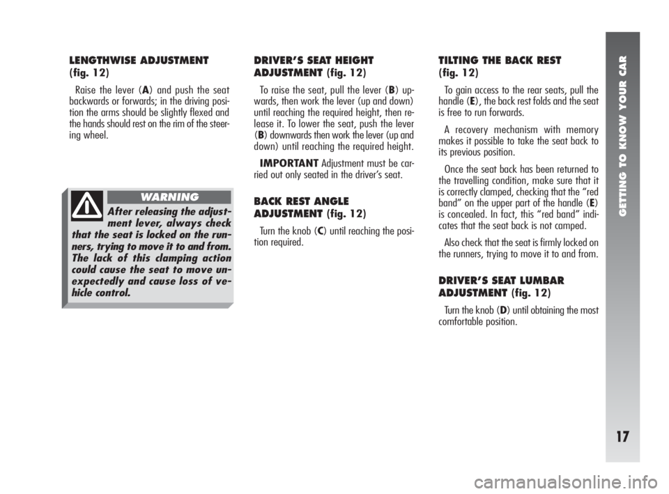
LENGTHWISE ADJUSTMENT
(fig. 12)
Raise the lever (A) and push the seat
backwards or forwards; in the driving posi-
tion the arms should be slightly flexed and
the hands should rest on the rim of the steer-
ing wheel.
DRIVER’S SEAT HEIGHT
ADJUSTMENT
(fig. 12)
To raise the seat, pull the lever (B) up-
wards, then work the lever (up and down)
until reaching the required height, then re-
lease it. To lower the seat, push the lever
(B) downwards then work the lever (up and
down) until reaching the required height.
IMPORTANTAdjustment must be car-
ried out only seated in the driver’s seat.
BACK REST ANGLE
ADJUSTMENT
(fig. 12)
Turn the knob (C) until reaching the posi-
tion required.
TILTING THE BACK REST
(fig. 12)
To gain access to the rear seats, pull the
handle (E), the back rest folds and the seat
is free to run forwards.
A recovery mechanism with memory
makes it possible to take the seat back to
its previous position.
Once the seat back has been returned to
the travelling condition, make sure that it
is correctly clamped, checking that the “red
band” on the upper part of the handle (E)
is concealed. In fact, this “red band” indi-
cates that the seat back is not camped.
Also check that the seat is firmly locked on
the runners, trying to move it to and from.
DRIVER’S SEAT LUMBAR
ADJUSTMENT
(fig. 12)
Turn the knob (D) until obtaining the most
comfortable position.
After releasing the adjust-
ment lever, always check
that the seat is locked on the run-
ners, trying to move it to and from.
The lack of this clamping action
could cause the seat to move un-
expectedly and cause loss of ve-
hicle control.
WARNING
Page 110 of 291
GETTING TO KNOW YOUR CAR
108
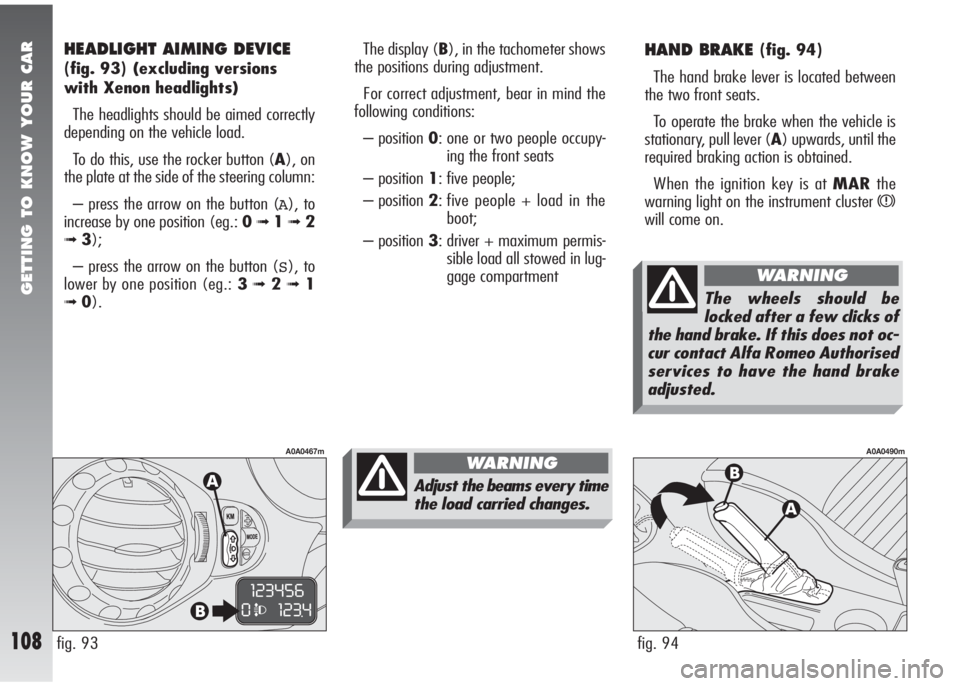
HAND BRAKE (fig. 94)
The hand brake lever is located between
the two front seats.
To operate the brake when the vehicle is
stationary, pull lever (A) upwards, until the
required braking action is obtained.
When the ignition key is at MARthe
warning light on the instrument cluster
x
will come on.
fig. 94
A0A0490m
The display (B), in the tachometer shows
the positions during adjustment.
For correct adjustment, bear in mind the
following conditions:
– position 0: one or two people occupy-
ing the front seats
– position 1: five people;
– position 2: five people + load in the
boot;
– position 3: driver + maximum permis-
sible load all stowed in lug-
gage compartment
fig. 93
A0A0467m
HEADLIGHT AIMING DEVICE
(fig. 93)(excluding versions
with Xenon headlights)
The headlights should be aimed correctly
depending on the vehicle load.
To do this, use the rocker button (A), on
the plate at the side of the steering column:
– press the arrow on the button (
A), to
increase by one position (eg.: 0
➟1➟ 2
➟3);
– press the arrow on the button (
S), to
lower by one position (eg.: 3
➟2➟1
➟0).
Adjust the beams every time
the load carried changes.
WARNING
The wheels should be
locked after a few clicks of
the hand brake. If this does not oc-
cur contact Alfa Romeo Authorised
services to have the hand brake
adjusted.
WARNING
Page 134 of 291
GETTING TO KNOW YOUR CAR
132fig. 135
A0A0199m
For correct adjustment, bear in mind the
following conditions:
– position 0: one or two people occupy-
ing the front seats
– position 1: five people;
– position 2: five people + load in the
boot;
– position 3: driver + maximum permis-
sible load all stowed in lug-
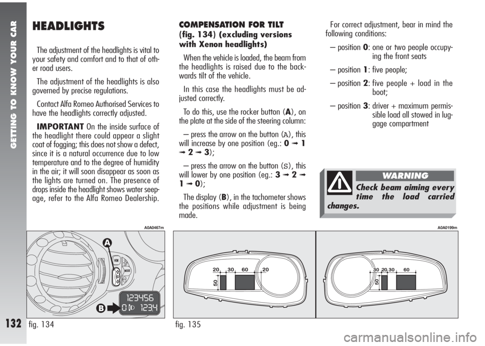
gage compartmentCOMPENSATION FOR TILT
(fig. 134)(excluding versions
with Xenon headlights)
When the vehicle is loaded, the beam from
the headlights is raised due to the back-
wards tilt of the vehicle.
In this case the headlights must be ad-
justed correctly.
To do this, use the rocker button (A), on
the plate at the side of the steering column:
– press the arrow on the button (
A), this
will increase by one position (eg.: 0
➟1
➟ 2➟3);
– press the arrow on the button (
S), this
will lower by one position (eg.: 3
➟2➟
1➟0);
The display (B), in the tachometer shows
the positions while adjustment is being
made.
fig. 134
A0A0467m
HEADLIGHTS
The adjustment of the headlights is vital to
your safety and comfort and to that of oth-
er road users.
The adjustment of the headlights is also
governed by precise regulations.
Contact Alfa Romeo Authorised Services to
have the headlights correctly adjusted.
IMPORTANTOn the inside surface of
the headlight there could appear a slight
coat of fogging; this does not show a defect,
since it is a natural occurrence due to low
temperature and to the degree of humidity
in the air; it will soon disappear as soon as
the lights are turned on. The presence of
drops inside the headlight shows water seep-
age, refer to the Alfa Romeo Dealership.
Check beam aiming every
time the load carried
changes.
WARNING
Page 268 of 291
RIGHT HAND DRIVE VERSION
266
FRONT SEATS
fig. 10
A0A0477m
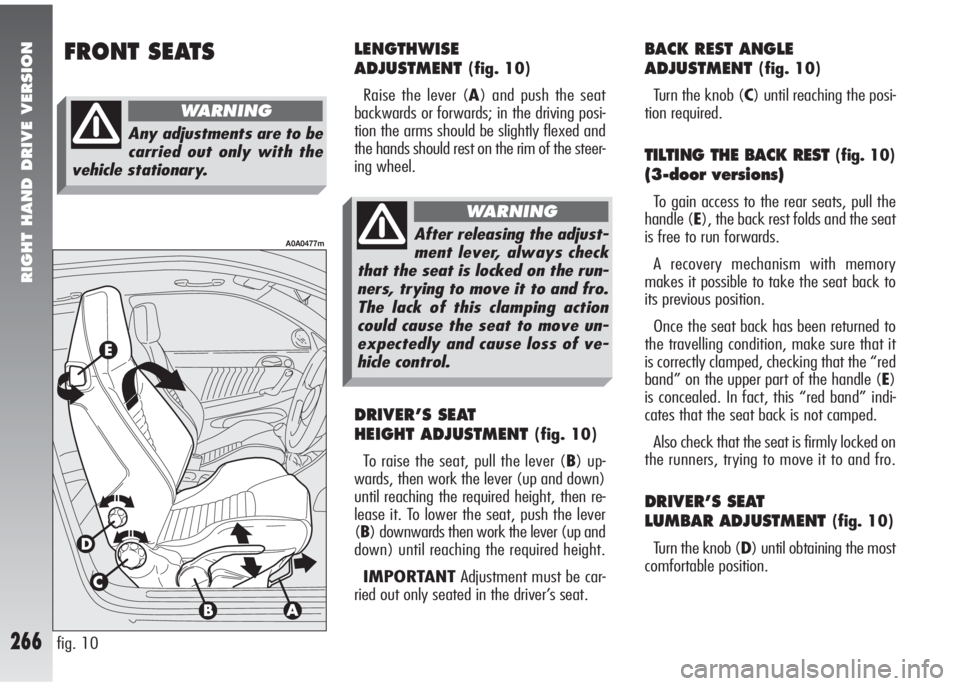
LENGTHWISE
ADJUSTMENT
(fig. 10)
Raise the lever (A) and push the seat
backwards or forwards; in the driving posi-
tion the arms should be slightly flexed and
the hands should rest on the rim of the steer-
ing wheel.
DRIVER’S SEAT
HEIGHT ADJUSTMENT
(fig. 10)
To raise the seat, pull the lever (B) up-
wards, then work the lever (up and down)
until reaching the required height, then re-
lease it. To lower the seat, push the lever
(B) downwards then work the lever (up and
down) until reaching the required height.
IMPORTANTAdjustment must be car-
ried out only seated in the driver’s seat.
BACK REST ANGLE
ADJUSTMENT
(fig. 10)
Turn the knob (C) until reaching the posi-
tion required.
TILTING THE BACK REST (fig. 10)
(3-door versions)
To gain access to the rear seats, pull the
handle (E), the back rest folds and the seat
is free to run forwards.
A recovery mechanism with memory
makes it possible to take the seat back to
its previous position.
Once the seat back has been returned to
the travelling condition, make sure that it
is correctly clamped, checking that the “red
band” on the upper part of the handle (E)
is concealed. In fact, this “red band” indi-
cates that the seat back is not camped.
Also check that the seat is firmly locked on
the runners, trying to move it to and fro.
DRIVER’S SEAT
LUMBAR ADJUSTMENT
(fig. 10)
Turn the knob (D) until obtaining the most
comfortable position.
Any adjustments are to be
carried out only with the
vehicle stationary.
WARNING
After releasing the adjust-
ment lever, always check
that the seat is locked on the run-
ners, trying to move it to and fro.
The lack of this clamping action
could cause the seat to move un-
expectedly and cause loss of ve-
hicle control.
WARNING
Page 274 of 291
RIGHT HAND DRIVE VERSION
272
HEADLIGHTS
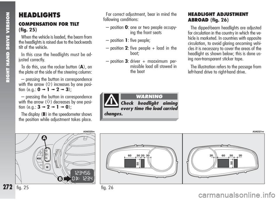
COMPENSATION FOR TILT
(fig. 25)
When the vehicle is loaded, the beam from
the headlights is raised due to the backwards
tilt of the vehicle.
In this case the headlights must be ad-
justed correctly.
To do this, use the rocker button (A), on
the plate at the side of the steering column:
– pressing the button in correspondence
with the arrow (
A) increases by one posi-
tion (e.g.: 0
➟1➟ 2➟3);
– pressing the button in correspondence
with the arrow (
S) decreases by one posi-
tion (e.g.: 3
➟2➟1➟0);
The display (B) in the speedometer shows
the position while adjustment takes place.
fig. 25
A0A0320m
HEADLIGHT ADJUSTMENT
ABROAD
(fig. 26)
The dipped-beam headlights are adjusted
for circulation in the country in which the ve-
hicle is marketed. In countries with opposite
circulation, to avoid glaring oncoming vehi-
cles it is necessary to cover the areas of the
headlight as shown below; this is done us-
ing non-transparent sticker tape.
The illustration refers to the passage from
left-hand drive to right-hand drive.
fig. 26
A0A0321m
For correct adjustment, bear in mind the
following conditions:
– position 0: one or two people occupy-
ing the front seats
– position 1: five people;
– position 2: five people + load in the
boot;
– position 3: driver + maaximum per-
missible load all stowed in
the boot
Check headlight aiming
every time the load carried
changes.
WARNING