engine Alfa Romeo 156 2004 Owner handbook (in English)
[x] Cancel search | Manufacturer: ALFA ROMEO, Model Year: 2004, Model line: 156, Model: Alfa Romeo 156 2004Pages: 357, PDF Size: 5.04 MB
Page 206 of 357

CORRECT USE OF THE CAR
204
REMOVING FROM STORAGEBefore using your vehicle after a long pe-
riod of inactivity, the following operations
should first be carried out:
– Do not dust the outside of the vehicle.
– Visually check that there are no leaks
(oil, brake and clutch fluid, engine coolant,
etc.).
– Replace engine oil and filter.
– Check:
- brake-clutch fluid level
- level of engine coolant fluid.
– Check the air cleaner and replace if nec-
essary.
– Check tyre pressure and ensure that they
are not damaged, cracked or cut. If they are
they must be replaced.– Check the state of the drive belts.
– Reconnect the battery negative termi-
nal (–) after checking that the charge is ad-
equate.
– With the gear lever in neutral start the
engine and allow the engine to run for a few
seconds whilst repeatedly working the clutch
pedal.
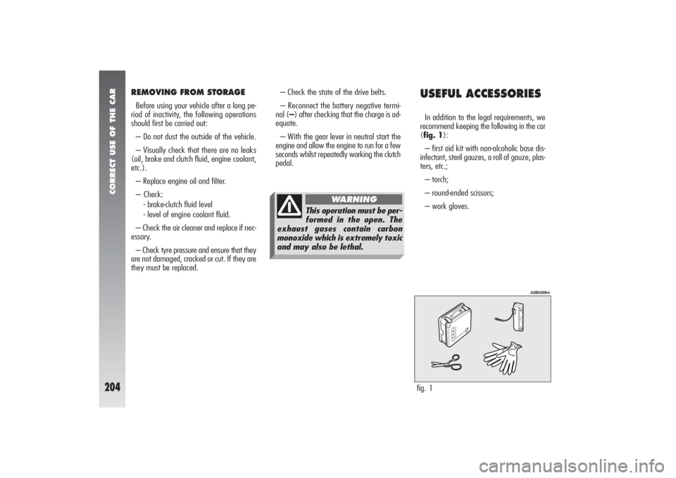
USEFUL ACCESSORIESIn addition to the legal requirements, we
recommend keeping the following in the car
(fig. 1):
– first aid kit with non-alcoholic base dis-
infectant, steril gauzes, a roll of gauze, plas-
ters, etc.;
– torch;
– round-ended scissors;
– work gloves.fig. 1
A0B0389m
This operation must be per-
formed in the open. The
exhaust gases contain carbon
monoxide which is extremely toxic
and may also be lethal.
WARNING
Page 207 of 357

IN AN EMERGENCY
205
3)Fully depress the accelerator pedal and
keep it pressed. The warning light
U
will
come on for eight seconds approximately
and will then go out; now release the ac-
celerator pedal.
4)The warning light
U
begins to flash:
after it has flashed for the same number of
times as the first digit on the code of the
card, press completely and hold down the
accelerator pedal until the warning light
U
comes on (for 4 seconds) and then goes out
again; now release the accelerator pedal.
5)The warning light
U
will begin to
flash: after it has flashed for the same num-
ber of times as the second digit on the code
of the card, press completely and hold down
the accelerator pedal.
6)Repeat this procedure in the same way
for the other digits on the CODE card code.
7)After entering the last figure, keep the
accelerator pedal pressed. The warning light
U
turns on (for four seconds) and then goes
off; now release the accelerator pedal.8)A quick flash of the warning light
U
(for appr. 4 seconds) confirms that the op-
eration has taken place correctly.
9)Start the car turning the ignition key
from theMAR position to the AVV posi-
tion without returning the key to theSTOP
position.
Conversely, if the warning light
U
stays
on, turn the ignition key to STOPand re-
peat the procedure starting from point 1.
WARNINGAfter emergency starting it
is advisable to turn to an Alfa Romeo Au-
thorized Service, because the procedure de-
scribed must be repeated each time the en-
gine is started.
EMERGENCY
STARTINGIf the Alfa Romeo CODE system is not able
to deactivate the engine inhibitor, warning
lights
Y
and
U
remain lit and the engine
cannot be started. To start the engine it is
necessary to follow the emergency starting
procedure.
WARNINGYou are advised to careful-
ly read the entire procedure before carry-
ing it out.
If a mistake is made during the emergency
procedure, the ignition key should be turned
to STOPand the operations must be re-
peated from the start (point 1).
1)Read the 5-figure electronic code on
the CODE card.
2)Turn the ignition key to theMAR po-
sition.
I I
N N
A A
N N
E E
M M
E E
R R
G G
E E
N N
C C
Y Y
Page 208 of 357

IN AN EMERGENCY
206
STARTING WITH AN
AUXILIARY BATTERYIf the battery is flat (for battery with op-
tical hydrometer: dark in colour with no
green area in the centre), the engine can be
started using another battery of the same
or a little higher capacity than the flat one.
This is what you should do fig. 1:
1)Remove the protecting cover on the
battery positive pole by pressing the related
side wings (front side), then connect the
positive terminals (plus sign +next to the
terminal) of the two batteries with a special
cable.
2)Connect a second cable to the negative
terminal (–) of the auxiliary battery with
an earth point
Eon the engine or the gear-
box of the car to be started.WARNINGDo not directly connect the
negative terminals of the two batteries: any
sparks may set fire to the gas that may be
released from the battery. If the auxiliary bat-
tery in installed on another car, no metal part
shall accidentally come into contact with this
car and the one with the flat battery.
3)Start the engine.
4)When the engine is running remove the
cables in reverse order.
If after a few attempts the engine does not
start, do not insist but contact Alfa Romeo
Authorized Services.
fig. 1
A0B0181m
Never use a quick battery
charger to start the engine
in an emergency as this
could damage the electronic sys-
tems of your vehicle, particularly
the control units which manage the
starting and supply functions.
The battery terminal con-
necting and disconnecting
operations generate cur-
rent that may cause problems to
the car’s electronic systems. There-
fore, this operation should be car-
ried out by skilled personnel.This starting procedure
must be carried out by
qualified personnel as incorrect op-
erations may provoke electrical
discharge of great intensity. The
liquid contained in the battery is
toxic and corrosive. Avoid contact
with skin and eyes. Keep naked
flame and lighted cigarettes away
from the battery. Do not cause
sparks.
WARNING
Page 209 of 357

IN AN EMERGENCY
207
STARTING BY INERTIA
IN THE EVENT OF A
PUNCTUREWARNINGIf the car is equipped with
“Fix&Go kit for tyre quick repair”, see the
instructions contained in the following
chapter.GENERAL INSTRUCTIONSWheel changing and correct use of the jack
and compact spare wheel call for some pre-
cautions as mentioned below. Never push, tow or coast
start the vehicle. This could
cause fuel to flow into the
catalyst damaging it irreversibly.
Remember that the engine
brake and power steering
are not operational until the engine
is started, therefore, much greater
effort than usual is needed on the
brake pedal and steering wheel.
WARNING
Signal the presence of the
stationary vehicle accord-
ing to the current regulations: haz-
ard warning lights, reflecting tri-
angle, etc.
Any passengers should leave the
car and wait for the wheel to be
changed out of harm of the traffic.
If parked on a slope or uneven road
surfaces, place wedges or other
suitable devices under the wheels
to prevent the car from rolling.
Never start the engine when the
car is raised on the jack.
When towing a trailer, always
remove the trailer before lifting
the car.
WARNING
Page 211 of 357

IN AN EMERGENCY
209
CHANGING A WHEEL(optional for versions/markets
where applicable)
You are informed that:
– The jack mass is 2,100 kg.
– The jack requires no adjustment.
– The jack cannot be repaired, in the event
of breakage it must be replaced by anoth-
er original one.
– No tools other than its operating crank
can be fitted to the jack.
To change the wheel proceed as follows:
– Stop the car in such a position that it is
not dangerous for the traffic, where it is pos-
sible to change the wheel safely. Where pos-
sible, park on a level, compact surface.– Stop the engine and engage the hand-
brake.
– Engage first gear or reverse.
– Lift the boot carpet and hook it as shown
in (fig. 1a).
– Loosen the clamping device (handle)
(A-fig. 2).
fig. 2
A0B0234m
fig. 1a
A0B0577m
Snow chains cannot be fit-
ted to the compact spare
wheel, so, if a front wheel is punc-
tured and chains need to be used,
the front axle should be fitted with
normal wheels and the spare
wheel fitted to the rear. In this
way, as two normal tyres are fit-
ted to the front of the vehicle,
snow chains can be mounted,
thereby overcoming an emergency.
Absolutely never tamper with the
inflation valve.
Do not insert tools of any kind be-
tween the rim and the tyre.
Routinely check that the pressure
of the tyres and of the compact
spare wheel is as specified in the
“Technical specifications” chapter.
WARNING
Page 216 of 357

IN AN EMERGENCY
214
INFLATING PROCEDURE 1)Place the wheel in the position illus-
trated in the figure (A-fig. 13) for the op-
eration with the valve, then engage the
handbrake.
2)Screw the filling pipe (B-fig. 14) to
the bottle (C).
3)Unscrew the tyre valve plug, remove
the element inside the valve by using the
appropriate tool (D-fig. 15); be careful
not to place it on the sand or on a dirty sur-
face .
4)Introduce the filling pipe (B-fig. 16)
in the tyre valve, keep the bottle (C-fig.
16) with the pipe directed downwards, then
press it so that the whole sealer can get in-
to the tyre.5)Screw again the element inside the
valve with the tool (D-fig. 17).
6)Use the appropriate lever (E-fig. 18)
to insert and clamp the air compressor pipe
(F) to the tyre valve.
7)Start the engine, insert the plug (G-
fig. 19) in the lighter (or socket 12V) and
inflate the tyre according to the right pres-
sure value (see “Cold inflation pressures” in
the “Technical specification” chapter). You
are advised to check the tyre pressure val-
ue on the pressure gauge (H-fig. 18) with
the compressor off, in order to have a more
accurate reading.fig. 13
A0B0334m
fig. 14
A0B335m
IT IS NECESSARY TO KNOW
THAT:The sealer included in the quick repairing
kit, good for temperatures between –30°C
e +80°C, is not adequate for permanent
fixing.
The liquid inside the tyre can be easily re-
moved with water.
The sealer has no expire date.
Do not operate the com-
pressor for more than 20
minutes. Risk of overheating.
WARNING
Page 217 of 357

IN AN EMERGENCY
215
After about 10 minutes, stop and check
the tyre pressure once again; remember to
engage the handbrake.
fig. 15
A0B0336m
fig. 16
A0B0337m
If it is not possible to reach the prescribed
pressure, move the car forwards or back-
wards for about 10 metres, so that the seal-
er is distributed inside the tyre, then repeat
inflation.
If, in spite of the last operation, the pre-
scribed pressure is not achieved, do not
move the vehicle and contact Alfa Romeo
Authorized Services.
Once the correct tyre pressure has been
reached, start driving immediately so that
the sealer is distributed evenly inside the
tyre.
Place the sticker in a posi-
tion where it can be clear-
ly seen by the driver as a notice
that the tyre has been treated with
the quick repairing kit. Drive care-
fully especially in a bend. Do not
overcome 80 km/h. Avoid sudden
acceleration or braking.
WARNING
If the pressure is below
1,3 bars, do not drive any
further; FIX & GO cannot guaran-
tee proper hold because the tyre is
too much damaged. Contact Alfa
Romeo Authorized Services.
Conversely, if at least 1,3 bars are
detected, restore the correct pres-
sure (with the engine running and
the handbrake engaged) and start
driving the car with great care.
WARNING
Page 237 of 357

IN AN EMERGENCY
235
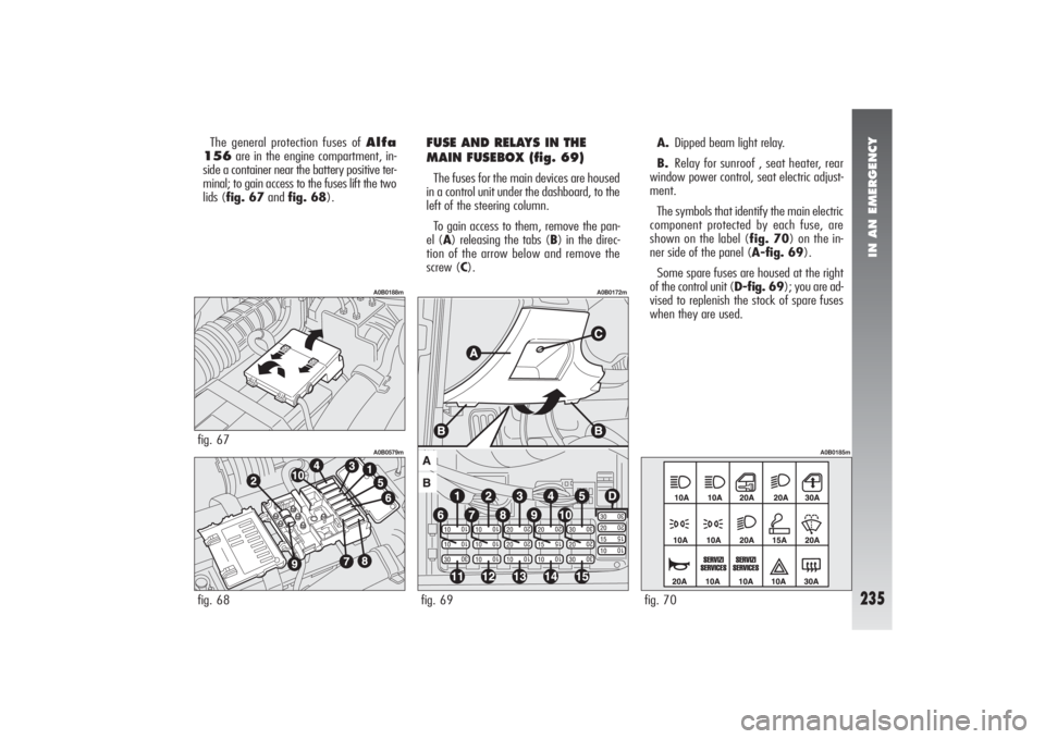
The general protection fuses of Alfa
156are in the engine compartment, in-
side a container near the battery positive ter-
minal; to gain access to the fuses lift the two
lids (fig. 67and fig. 68).
FUSE AND RELAYS IN THE
MAIN FUSEBOX (fig. 69)The fuses for the main devices are housed
in a control unit under the dashboard, to the
left of the steering column.
To gain access to them, remove the pan-
el (A) releasing the tabs (B) in the direc-
tion of the arrow below and remove the
screw (C).A.Dipped beam light relay.
B.Relay for sunroof , seat heater, rear
window power control, seat electric adjust-
ment.
The symbols that identify the main electric
component protected by each fuse, are
shown on the label (fig. 70) on the in-
ner side of the panel (A-fig. 69).
Some spare fuses are housed at the right
of the control unit (D-fig. 69); you are ad-
vised to replenish the stock of spare fuses
when they are used.
fig. 68
A0B0579m
fig. 67
A0B0188m
fig. 69
A0B0172m
fig. 70
A0B0185m
Page 238 of 357

IN AN EMERGENCY
236
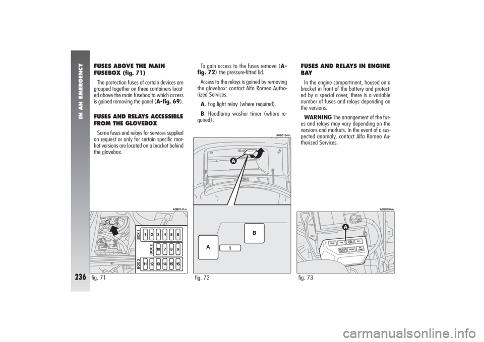
FUSES ABOVE THE MAIN
FUSEBOX
(fig. 71)
The protection fuses of certain devices are
grouped together on three containers locat-
ed above the main fusebox to which access
is gained removing the panel (A-fig. 69).
FUSES AND RELAYS ACCESSIBLE
FROM THE GLOVEBOX Some fuses and relays for services supplied
on request or only for certain specific mar-
ket versions are located on a bracket behind
the glovebox.To gain access to the fuses remove (A-
fig. 72) the pressure-fitted lid.
Access to the relays is gained by removing
the glovebox: contact Alfa Romeo Autho-
rized Services.
A. Fog light relay (where required).
B. Headlamp washer timer (where re-
quired).
FUSES AND RELAYS IN ENGINE
BAYIn the engine compartment, housed on a
bracket in front of the battery and protect-
ed by a special cover, there is a variable
number of fuses and relays depending on
the versions.
WARNINGThe arrangement of the fus-
es and relays may vary depending on the
versions and markets. In the event of a sus-
pected anomaly, contact Alfa Romeo Au-
thorized Services.fig. 73
A0B0154m
fig. 71
A0B0141m
fig. 72
A0B0184m
Page 239 of 357

IN AN EMERGENCY
237
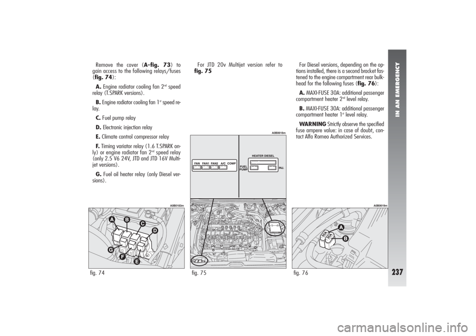
Remove the cover (A-fig. 73) to
gain access to the following relays/fuses
(fig. 74):
A.Engine radiator cooling fan 2
ndspeed
relay (T.SPARK versions).
B.Engine radiator cooling fan 1
stspeed re-
lay.
C.Fuel pump relay
D.Electronic injection relay
E.Climate control compressor relay
F.Timing variator relay (1.6 T.SPARK on-
ly) or engine radiator fan 2
ndspeed relay
(only 2.5 V6 24V, JTD and JTD 16V Multi-
jet versions).
G.Fuel oil heater relay (only Diesel ver-
sions).For JTD 20v Multijet version refer to
fig. 75For Diesel versions, depending on the op-
tions installed, there is a second bracket fas-
tened to the engine compartment rear bulk-
head for the following fuses (fig. 76):
A.MAXI-FUSE 30A: additional passenger
compartment heater 2
ndlevel relay.
B.MAXI-FUSE 30A: additional passenger
compartment heater 1stlevel relay.
WARNINGStrictly observe the specified
fuse ampere value: in case of doubt, con-
tact Alfa Romeo Authorized Services.
fig. 74
A0B0183m
fig. 76
A0B0619m
fig. 75
A0B0618m