ABS Alfa Romeo 156 2005 Owner handbook (in English)
[x] Cancel search | Manufacturer: ALFA ROMEO, Model Year: 2005, Model line: 156, Model: Alfa Romeo 156 2005Pages: 357, PDF Size: 5.04 MB
Page 197 of 357
CORRECT USE OF THE CAR
195
DRIVING ON SNOW AND ICEHere are few suggestions for driving in
these conditions:
– Keep your speed down.
– On a snowy road, fit winter tyres or
snow chains; see the related paragraphs in
this section.
– Use exhaust brake where possible and
avoid abrupt braking.
– Avoid abrupt acceleration and changes
of direction.
– During cold weather even apparently dry
roads may be covered with occasional
patches of ice. Pay great attention therefore
when driving on roads which are in the
shade, or where rocks or trees line the road
and on which ice may persist.
– Keep further back from the vehicle in
front.
DRIVING WITH ABSThe ABS is a part of the braking system
which essentially offers two advantages:
1)It prevents wheel lock-up and conse-
quent skidding in emergency stops, partic-
ularly when the road does not offer much
grip;
2)It makes it possible to brake and steer
at the same time so you can avoid unex-
pected obstacles and direct the car where
you want while braking. The extent to which
this can be done will depend on the physi-
cal limits of the tyre’s sideways grip.
To make the most of the ABS:
– In emergency braking or when grip is
low, a slight pulsing can be felt on the brake
pedal: this means that the ABS has come
into action. Do not release the pedal, but
continue pressing it to give continuity to the
braking action.
– The ABS prevents the wheels from lock-
ing but it does not increase the physical lim-
its of grip between the asphalt and the road.
Therefore, also with a car fitted with ABS,
keep within a safety distance from the ve-
hicle in front and limit speed when ap-
proaching bends.
The ABS serves to increase car controlla-
bilty not to go faster.
REDUCING RUNNING
COSTS AND
ENVIRONMENT
POLLUTIONSome suggestions which may help you to
keep the running costs of your vehicle down
and lower the amount of toxic emissions re-
leased into the atmosphere are given below.GENERAL CONSIDERATIONSVehicle maintenance
The overalll state of the vehicle is an im-
portant factor which has a marked influence
over fuel consumption and driving comfort
and on the life span of your vehicle. For this
reason care should be taken to maintain
your vehicle by carrying out the necessary
checks and regulations in accordance with
specifications given in the “Scheduled Main-
tenance Programme” (see sections... spark
plugs, air cleaner, timing).
Page 201 of 357

CORRECT USE OF THE CAR
199
TOWING TRAILERSWARNINGS AND
SUGGESTIONS For towing caravans or trailers the vehi-
cle must be fitted with a certified tow hook
and an adequate electric system. Installa-
tion should be carried out by specialised per-
sonnel who release a special document for
circulation on the road.
Install any specific and/or additional rear-
view mirrors as specified by law. Remember
that when towing a trailer, steep hills are
harder to climb, the braking spaces increase
and overtaking takes longer depending on
the overall weight.
Engage a low gear when driving downhill,
rather than constantly using the brake.
The weight the trailer exerts on the vehi-
cle tow hook reduces by the same amount
the actual vehicle loading capacity. To make sure the maximum towable
weight is not exceeded (given in the log
book) account should be taken of the fully
laden trailer, including accessories and per-
sonal belongings.
Drive within the permitted speed limits for
vehicles with trailers. In any case the maxi-
mum speed should never exceed 100 km/h.
INSTALLING THE TOW HOOKThe towing device should be fastened to
the body by specialised personnel according
to the following instructions and any addi-
tional and/or integrative information sup-
plied by the Manufacturer of the device.
The towing device must meet current reg-
ulations with reference to 94/20/EC Di-
rective and subsequent amendments.
For any version the towing device used
must match the towable weight of the ve-
hicle on which it is to be installed.
For the electric connection a unified con-
nector should be used which is generally
placed on a special bracket normally fas-
tened to the towing device.
The ABS system with
which the car may be fitted
does not control the trailer braking
system. Particular care is therefore
necessary on slippery surfaces.
WARNING
Under no circumstances
should the vehicle brake
system be altered to control the
trailer brake. The trailer braking
system must be fully independent
of the vehicle’s hydraulic system.
WARNING
Page 211 of 357
IN AN EMERGENCY
209
CHANGING A WHEEL(optional for versions/markets
where applicable)
You are informed that:
– The jack mass is 2,100 kg.
– The jack requires no adjustment.
– The jack cannot be repaired, in the event
of breakage it must be replaced by anoth-
er original one.
– No tools other than its operating crank
can be fitted to the jack.
To change the wheel proceed as follows:
– Stop the car in such a position that it is
not dangerous for the traffic, where it is pos-
sible to change the wheel safely. Where pos-
sible, park on a level, compact surface.– Stop the engine and engage the hand-
brake.
– Engage first gear or reverse.
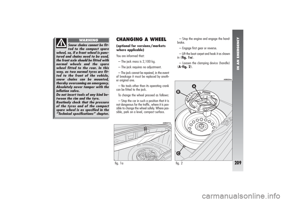
– Lift the boot carpet and hook it as shown
in (fig. 1a).
– Loosen the clamping device (handle)
(A-fig. 2).
fig. 2
A0B0234m
fig. 1a
A0B0577m
Snow chains cannot be fit-
ted to the compact spare
wheel, so, if a front wheel is punc-
tured and chains need to be used,
the front axle should be fitted with
normal wheels and the spare
wheel fitted to the rear. In this
way, as two normal tyres are fit-
ted to the front of the vehicle,
snow chains can be mounted,
thereby overcoming an emergency.
Absolutely never tamper with the
inflation valve.
Do not insert tools of any kind be-
tween the rim and the tyre.
Routinely check that the pressure
of the tyres and of the compact
spare wheel is as specified in the
“Technical specifications” chapter.
WARNING
Page 218 of 357

IN AN EMERGENCY
216
Drive carefully to the nearest Alfa Romeo
Authorized Service to check the tyre condi-
tions, then have it fixed or replaced.
It is absolutely necessary to communicate
that the tyre has been fixed with the quick
repairing kit.
fig. 18
A0B0339m
fig. 19
A0B0391m
fig. 17
A0B0338m
If, during the pressure
restoring operation, it is
not possible to reach at least 1,8
bars, do not drive any further be-
cause the tyre is too much dam-
aged and the quick repairing kit
cannot guarantee proper hold. Con-
tact Alfa Romeo Authorized Ser-
vices.
WARNING
Tyres fixed with the quick
repairing kit must be used
only temporarily.
WARNING
Page 226 of 357

IN AN EMERGENCY
224
– Refit the bulb holder (A-fig. 31) by
making its notches coincide with the grooves
in the headlight unit body and turn it clock-
wise.
fig. 32
A0B0222m
fig. 31
A0B0221m
DIPPED-BEAM HEADLAMPS(fig. 32)
To replace the bulb proceed as follows:
– Remove the protective cover
– Disconnect the electrical connector (A).
– Release the bulb catch (B).
– Withdraw the bulb and replace it.– Fit the new bulb making the tabs of the
metallic part coincide with the grooves in the
headlamp parabola and hook the bulb catch
(B).
– Reconnect the electrical connector (A).
– Refit the protective cover correctly.
Page 227 of 357

IN AN EMERGENCY
225
To adjust the front fog-
lights contact Alfa Romeo
Authorized Services.
FRONT FOG LIGHTS(where required)
To replace the bulb proceed under the car
as follows:
– Disconnect the connector (A-fig. 33)
from the light unit.
– Turn the cover counter-clockwise (B-
fig. 33) and remove it.
– Withdraw the supply cable terminal
(C-fig. 34).
– Release the bulb stopper (D-fig. 34)
and remove the bulb.– Fit a new bulb making the tabs of the
metallic part coincide with the grooves in
the lamp lens and hook the bulb stopper
(D-fig. 34).
– Re-connect the supply cable terminal
(C-fig. 34).
– refit the cover (B-fig. 33) and con-
nect the connector (A-fig. 33) to the light
unit.fig. 33
A0B0215m
fig. 34
A0B0216m
The efficiency of the lights
will be decreased and may
inconvenience other road users if the
light units are not correctly adjust-
ed. If in doubt contact Alfa Romeo
Authorized Services to have them
checked and adjusted if necessary.
WARNING
Page 228 of 357

IN AN EMERGENCY
226
FRONT SIDELIGHTS To replace the bulb proceed as follows:
– Remove the protective cover (A-
fig. 35).
– Remove the bulb holder (B-fig. 35)
which is snap-fitted.
– Remove the bulb (C-fig. 36) from the
bulb holder, pushing lightly and turning
counter-clockwise.
– Replace the bulb and refit the bulb hold-
er (B-fig. 36) in its housing.
– Refit the protective cover correctly
(A-fig. 35).
MAIN-BEAM HEADLAMPS (fig. 37)
To replace the bulb proceed as follows:
– Remove the protective cover.
– Release the clip holding the bulb (A).
– Withdraw the power supply (B) cable
connector.
– Remove and (C) replace the bulb.
– Reconnect the power cable (B) to the
bulb.
fig. 35
A0B0217m
fig. 36
A0B0218m
– Fit the new bulb making the tabs of the
metallic part coincide with the grooves in the
headlamp parabola.
– Lock the bulb in place with the clip (A).
– Refit the protective cover correctly.fig. 37
A0B0223m
Page 230 of 357

IN AN EMERGENCY
228
DIRECTION INDICATORS/
SIDELIGHTS AND STOP LIGHTS To replace the bulbs proceed as follows:
– Open the boot.
– Slacken the two fastening screws
(A-fig. 43) and remove the protective cov-
er (B-fig. 43).
– Withdraw the bulb holder unit (A-
fig. 44) releasing the retainer tabs (B-
fig. 44). – Refit the bulb holder unit fastening it cor-
rectly in place with the retainer tabs (B-
fig. 41).
– Refit the boot trim fastening it with the
screws removed previously.
fig. 41
A0B0212m
fig. 42
A0B0213m
fig. 43
A0B0214m
– Lower the boot lid trim in the corre-
sponding area and remove the bulb holder
unit (C-fig. 41) releasing the retainer tab
(B-fig. 41).
– Remove and replace the spherical type
bulb with bayonet attachment pushing
it gently and turning counter-clockwise
(fig. 42):
(D) reversing light bulb
(E) rear fog guard bulb.
Page 231 of 357
IN AN EMERGENCY
229
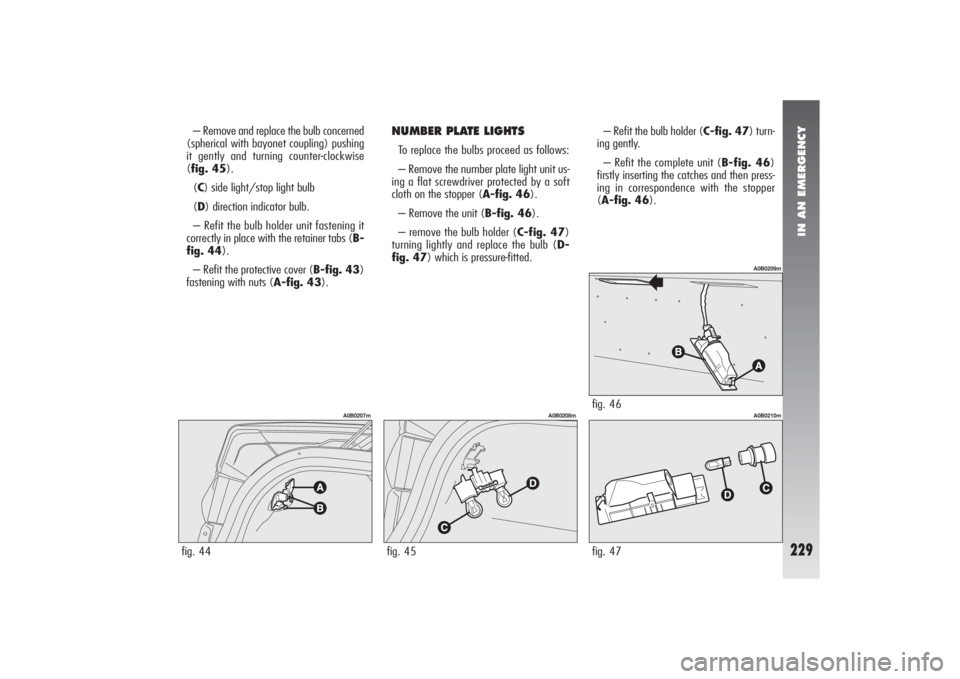
– Remove and replace the bulb concerned
(spherical with bayonet coupling) pushing
it gently and turning counter-clockwise
(fig. 45).
(C) side light/stop light bulb
(D) direction indicator bulb.
– Refit the bulb holder unit fastening it
correctly in place with the retainer tabs (B-
fig. 44).
– Refit the protective cover (B-fig. 43)
fastening with nuts (A-fig. 43).
NUMBER PLATE LIGHTSTo replace the bulbs proceed as follows:
– Remove the number plate light unit us-
ing a flat screwdriver protected by a soft
cloth on the stopper (A-fig. 46).
– Remove the unit (B-fig. 46).
– remove the bulb holder (C-fig. 47)
turning lightly and replace the bulb (D-
fig. 47) which is pressure-fitted.– Refit the bulb holder (C-fig. 47) turn-
ing gently.
– Refit the complete unit (B-fig. 46)
firstly inserting the catches and then press-
ing in correspondence with the stopper
(A-fig. 46).
fig. 44
A0B0207m
fig. 45
A0B0208m
fig. 47
A0B0210m
fig. 46
A0B0209m
Page 235 of 357

IN AN EMERGENCY
233
– Change the bulb (C-fig. 62) which
is pressure-fitted.
– Refit the cover (B-fig. 61).
– Re-install the light inserting it in the cor-
rect position firstly on one side and then
pushing on the other until the tab clicks.
LUGGAGE COMPARTMENT
LIGHTTo remove the bulb proceed as follows:
– Open the boot.
– Turn the fastening buttons (A-fig. 63)
until they click and lower the trim.
– Withdraw the clear plastic cover and
bulb (A-fig. 64) using a flat-bladed screw-
driver.– Replace the bulb (B-fig. 65)of the
cylindrical type pulling it outwards ensuring
that the new bulb is correctly positioned be-
tween the contacts.
– Refit the transparent cover ensuring that
the retaining tabs click into place (C-
fig. 65).
fig. 61
A0B0194m
fig. 62
A0B0193m
fig. 65
A0B0190m
fig. 64
A0B0191m
fig. 63
A0B0192m