lights Alfa Romeo 156 2005 Owner handbook (in English)
[x] Cancel search | Manufacturer: ALFA ROMEO, Model Year: 2005, Model line: 156, Model: Alfa Romeo 156 2005Pages: 357, PDF Size: 5.04 MB
Page 207 of 357

IN AN EMERGENCY
205
3)Fully depress the accelerator pedal and
keep it pressed. The warning light
U
will
come on for eight seconds approximately
and will then go out; now release the ac-
celerator pedal.
4)The warning light
U
begins to flash:
after it has flashed for the same number of
times as the first digit on the code of the
card, press completely and hold down the
accelerator pedal until the warning light
U
comes on (for 4 seconds) and then goes out
again; now release the accelerator pedal.
5)The warning light
U
will begin to
flash: after it has flashed for the same num-
ber of times as the second digit on the code
of the card, press completely and hold down
the accelerator pedal.
6)Repeat this procedure in the same way
for the other digits on the CODE card code.
7)After entering the last figure, keep the
accelerator pedal pressed. The warning light
U
turns on (for four seconds) and then goes
off; now release the accelerator pedal.8)A quick flash of the warning light
U
(for appr. 4 seconds) confirms that the op-
eration has taken place correctly.
9)Start the car turning the ignition key
from theMAR position to the AVV posi-
tion without returning the key to theSTOP
position.
Conversely, if the warning light
U
stays
on, turn the ignition key to STOPand re-
peat the procedure starting from point 1.
WARNINGAfter emergency starting it
is advisable to turn to an Alfa Romeo Au-
thorized Service, because the procedure de-
scribed must be repeated each time the en-
gine is started.
EMERGENCY
STARTINGIf the Alfa Romeo CODE system is not able
to deactivate the engine inhibitor, warning
lights
Y
and
U
remain lit and the engine
cannot be started. To start the engine it is
necessary to follow the emergency starting
procedure.
WARNINGYou are advised to careful-
ly read the entire procedure before carry-
ing it out.
If a mistake is made during the emergency
procedure, the ignition key should be turned
to STOPand the operations must be re-
peated from the start (point 1).
1)Read the 5-figure electronic code on
the CODE card.
2)Turn the ignition key to theMAR po-
sition.
I I
N N
A A
N N
E E
M M
E E
R R
G G
E E
N N
C C
Y Y
Page 209 of 357

IN AN EMERGENCY
207
STARTING BY INERTIA
IN THE EVENT OF A
PUNCTUREWARNINGIf the car is equipped with
“Fix&Go kit for tyre quick repair”, see the
instructions contained in the following
chapter.GENERAL INSTRUCTIONSWheel changing and correct use of the jack
and compact spare wheel call for some pre-
cautions as mentioned below. Never push, tow or coast
start the vehicle. This could
cause fuel to flow into the
catalyst damaging it irreversibly.
Remember that the engine
brake and power steering
are not operational until the engine
is started, therefore, much greater
effort than usual is needed on the
brake pedal and steering wheel.
WARNING
Signal the presence of the
stationary vehicle accord-
ing to the current regulations: haz-
ard warning lights, reflecting tri-
angle, etc.
Any passengers should leave the
car and wait for the wheel to be
changed out of harm of the traffic.
If parked on a slope or uneven road
surfaces, place wedges or other
suitable devices under the wheels
to prevent the car from rolling.
Never start the engine when the
car is raised on the jack.
When towing a trailer, always
remove the trailer before lifting
the car.
WARNING
Page 219 of 357
IN AN EMERGENCY
217
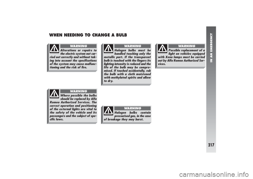
WHEN NEEDING TO CHANGE A BULB
Alterations or repairs to
the electric system not car-
ried out correctly and without tak-
ing into account the specifications
of the system may cause malfunc-
tioning and the risk of fire.
WARNING
Where possible the bulbs
should be replaced by Alfa
Romeo Authorized Services. The
correct operation and positioning
of the external lights are vital to
the safety of the vehicle and its
passengers and the subject of spe-
cific laws.
WARNING
Halogen bulbs must be
handled touching only the
metallic part. If the transparent
bulb is touched with the fingers its
lighting intensity is reduced and the
life of the bulb may be compro-
mised. If touched accidentally, rub
the bulb with a cloth moistened
with methylated spirits and allow
to dry.
WARNING
Halogen bulbs contain
pressurised gas, in the case
of breakage they may burst.
WARNING
Possible replacement of a
light on vehicles equipped
with Xeno lamps must be carried
out by Alfa Romeo Authorized Ser-
vices.
WARNING
Page 222 of 357

IN AN EMERGENCY
220
IF ONE OF THE
EXTERNAL LIGHTS
GOES OUT
FRONT LIGHT UNITSThe front light units contain the direction
indicators, side lights/dipped and main
beam light bulbs.
To replace these bulbs the cover must be
removed turning counter-clockwise.
The bulbs are arranged inside the light
units as follows (fig. 21):
A.Direction indicators
B.Dipped beam headlights
C.Sidelight/main beam headlights.
WARNINGFor the type and power of
the light refer to what described in the pre-
vious chapter “If one of the lights needs to
be replaced”.When the bulbs have
been replaced refit the cov-
er in the correct position
turning clockwise and ensuring that
it clicks into place.
fig. 22
A0B0392m
fig. 21
A0B0224m
Fig. 22:Dipped beam headlights with
Xeno lamp
A.Sidelight/main beam headlights
B.Dipped beam headlights/sidelight.
Alterations or repairs to
the electric system not car-
ried out correctly and without tak-
ing into account the specifications
of the system may cause malfunc-
tioning and the risk of fire.
WARNING
Page 223 of 357

IN AN EMERGENCY
221
REPLACEMENT OF XENON
LIGHTS
(optional for versions/
markets where applicable)
Xenon lights have a very long life, there-
fore breakdowns are unlikely.
Hereafter you find the description of the
correct procedure to replace a Xenon light.– Rotate the connector (B-fig. 24) of
the Xenon lamp by a quarter of a turn
counter-clockwise, as indicated in fig. 25,
and remove it.
Dipped-beam headlamps
To replace the bulb proceed as follows:
– Unscrew the three locking screw (B-
fig. 23) and remove the protective (A)
cover.
fig. 23
A0B0348m
fig. 25
A0B0351m
fig. 24
A0B0349m
If necessary, have the sys-
tem checked and repaired
only by Alfa Romeo Authorized
Services.
WARNING
Any operation regarding
the front light units must
be carried out with the lights
turned off and the ignition key re-
moved from the ignition switch:
risk of electric discharges.
WARNING
Page 225 of 357

IN AN EMERGENCY
223
FRONT DIRECTION
INDICATORS To replace the bulb (orange colour), pro-
ceed as follows:
– Turn the bulb holder counter-clockwise
(A-fig. 30) and remove it.
– Remove the bulb (B-fig. 31) from the
bulb holder (A-fig. 31), pushing lightly
and turning counter-clockwise.
– Replace the bulb (B-fig. 31). Direction indicators
To replace the bulb proceed as follows:
– Turn the cover counter-clockwise
(A-fig. 29).
– Turn the bulb holder (B) counter-clock-
wise.
– Remove the bulb from the bulb holder,
pushing lightly and turning counter-clock-
wise.
– Replace the bulb and refit the bulb hold-
er in its housing.fig. 30
A0B0225m
Sidelights
To replace the bulb proceed as follows:
– Turn the protective cover (C-fig. 23)
counter-clockwise in order to reach the side-
light bulb.
– Remove the bulb (A-fig. 28) from the
bulb holder (B), pushing lightly and turning
counter-clockwise.
– Replace the bulb and refit the bulb hold-
er (B-fig. 28) in its housing.
– Refit the protective cover correctly
(C-fig. 23).
fig. 29
A0B0353m
Page 227 of 357

IN AN EMERGENCY
225
To adjust the front fog-
lights contact Alfa Romeo
Authorized Services.
FRONT FOG LIGHTS(where required)
To replace the bulb proceed under the car
as follows:
– Disconnect the connector (A-fig. 33)
from the light unit.
– Turn the cover counter-clockwise (B-
fig. 33) and remove it.
– Withdraw the supply cable terminal
(C-fig. 34).
– Release the bulb stopper (D-fig. 34)
and remove the bulb.– Fit a new bulb making the tabs of the
metallic part coincide with the grooves in
the lamp lens and hook the bulb stopper
(D-fig. 34).
– Re-connect the supply cable terminal
(C-fig. 34).
– refit the cover (B-fig. 33) and con-
nect the connector (A-fig. 33) to the light
unit.fig. 33
A0B0215m
fig. 34
A0B0216m
The efficiency of the lights
will be decreased and may
inconvenience other road users if the
light units are not correctly adjust-
ed. If in doubt contact Alfa Romeo
Authorized Services to have them
checked and adjusted if necessary.
WARNING
Page 228 of 357

IN AN EMERGENCY
226
FRONT SIDELIGHTS To replace the bulb proceed as follows:
– Remove the protective cover (A-
fig. 35).
– Remove the bulb holder (B-fig. 35)
which is snap-fitted.
– Remove the bulb (C-fig. 36) from the
bulb holder, pushing lightly and turning
counter-clockwise.
– Replace the bulb and refit the bulb hold-
er (B-fig. 36) in its housing.
– Refit the protective cover correctly
(A-fig. 35).
MAIN-BEAM HEADLAMPS (fig. 37)
To replace the bulb proceed as follows:
– Remove the protective cover.
– Release the clip holding the bulb (A).
– Withdraw the power supply (B) cable
connector.
– Remove and (C) replace the bulb.
– Reconnect the power cable (B) to the
bulb.
fig. 35
A0B0217m
fig. 36
A0B0218m
– Fit the new bulb making the tabs of the
metallic part coincide with the grooves in the
headlamp parabola.
– Lock the bulb in place with the clip (A).
– Refit the protective cover correctly.fig. 37
A0B0223m
Page 229 of 357

IN AN EMERGENCY
227
REAR LIGHT UNITSRear light units contain the reversing lights,
rear fog guards, direction indicators, num-
ber plate lights, stop/side lights and the ad-
ditional stop light (3rd stop).REVERSING LIGHTS AND REAR
FOG GUARDS To replace the bulbs proceed as follows:
– Open the boot.
– Slacken the screws (Aor B-fig. 40)
fastening the boot trim in correspondence
with the light concerned.fig. 40
A0B0211m
SIDE DIRECTION INDICATORSTo replace the bulb proceed as follows:
– Push the transparent cover towards the
rear of the car to compress the tab (A-
fig. 38). Release the front part and re-
move the unit.
– Turn the bulb holder counter-clockwise
(B-fig. 39) and remove it from the trans-
parent cover (D-fig. 39).
Take care not to damage
the bodywork or the trans-
parent cover when remov-
ing the side direction indicator unit.fig. 38
A0B0219m
fig. 39
A0B0220m
– Withdraw the bulb (C-fig. 39) which
is of the pressure-fitted type and replace it.
– Insert the bulb holder (B-fig. 39) in
the transparent cover (D-fig. 39) and po-
sition the unit ensuring that the clip clicks in-
to place (A-fig. 38).
Page 230 of 357

IN AN EMERGENCY
228
DIRECTION INDICATORS/
SIDELIGHTS AND STOP LIGHTS To replace the bulbs proceed as follows:
– Open the boot.
– Slacken the two fastening screws
(A-fig. 43) and remove the protective cov-
er (B-fig. 43).
– Withdraw the bulb holder unit (A-
fig. 44) releasing the retainer tabs (B-
fig. 44). – Refit the bulb holder unit fastening it cor-
rectly in place with the retainer tabs (B-
fig. 41).
– Refit the boot trim fastening it with the
screws removed previously.
fig. 41
A0B0212m
fig. 42
A0B0213m
fig. 43
A0B0214m
– Lower the boot lid trim in the corre-
sponding area and remove the bulb holder
unit (C-fig. 41) releasing the retainer tab
(B-fig. 41).
– Remove and replace the spherical type
bulb with bayonet attachment pushing
it gently and turning counter-clockwise
(fig. 42):
(D) reversing light bulb
(E) rear fog guard bulb.