reset Alfa Romeo 159 2005 Owner handbook (in English)
[x] Cancel search | Manufacturer: ALFA ROMEO, Model Year: 2005, Model line: 159, Model: Alfa Romeo 159 2005Pages: 275, PDF Size: 3.98 MB
Page 8 of 275
6
SAFETY
DEVICES
WARNING
LIGHTS AND
MESSAGES
IN AN
EMERGENCY
CAR
MAINTENANCE
TECHNICAL
SPECIFICATIONS
INDEX
CORRECT USE
OF THE CAR
DASHBOARD
AND
CONTROLS
D D
A A
S S
H H
B B
O O
A A
R R
D D
A A
N N
D D
C C
O O
N N
T T
R R
O O
L L
S S
CRUISE CONTROL .............................................. 76
CEILING LIGHTS ................................................. 78
CONTROLS ........................................................ 81
INTERIOR FITTINGS............................................. 83
SUNROOF ......................................................... 89
DOORS ............................................................ 92
POWER WINDOWS ............................................ 95
BOOT ............................................................... 97
BONNET............................................................ 101
ROOF RACK/SKI RACK ....................................... 102
HEADLIGHTS...................................................... 102
ABS SYSTEM .................................................... 104
VDC SYSTEM .................................................... 106
EOBD SYSTEM .................................................. 111
SOUND SYSTEM PRESETTING .............................. 112
ACCESSORIES PURCHASED BY THE OWNER .......... 113
PARKING SENSORS ............................................ 114
TYRE PRESSURE MONITORING SYSTEM
(T.P.M.S.) ......................................................... 118
AT THE FILLING STATION ..................................... 121
PROTECTING THE ENVIRONMENT ......................... 123 DASHBOARD...................................................... 7
INSTRUMENT PANEL .......................................... 8
SYMBOLS ........................................................ 9
ALFA ROMEO CODE SYSTEM ................................ 9
ELECTRONIC KEY ............................................... 11
ALARM ............................................................ 17
IGNITION DEVICE................................................ 19
INSTRUMENTS ................................................... 21
MULTIFUNCTION DISPLAY .................................... 24
RECONFIGURABLE MULTIFUNCTION DISPLAY .......... 30
SEATS .............................................................. 46
HEAD RESTRAINTS.............................................. 48
STEERING WHEEL .............................................. 49
REARVIEW MIRRORS .......................................... 50
CLIMATE CONTROL SYSTEM ................................ 53
MANUAL CLIMATE CONTROL SYSTEM ................... 55
AUTOMATIC TWO-/THREE-ZONE
CLIMATE CONTROL SYSTEM ................................ 58
ADDITIONAL HEATER .......................................... 69
EXTERNAL LIGHTS .............................................. 70
WINDOW WASHING .......................................... 73
Page 9 of 275
7
SAFETY
DEVICES
WARNING LIGHTS
AND MESSAGES
IN AN
EMERGENCY
CAR
MAINTENANCE
TECHNICAL
SPECIFICATIONS
INDEX
DASHBOARD
AND
CONTROLS
CORRECT USE
OF THE CAR
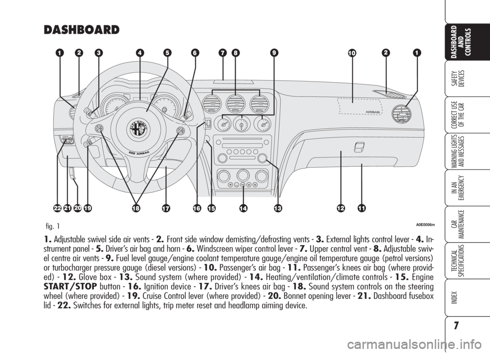
DASHBOARD
A0E0056mfig. 1
1.Adjustable swivel side air vents - 2.Front side window demisting/defrosting vents - 3.External lights control lever - 4.In-
strument panel - 5.Driver’s air bag and horn -6.Windscreen wiper control lever - 7.Upper central vent - 8.Adjustable swiv-
el centre air vents - 9.Fuel level gauge/engine coolant temperature gauge/engine oil temperature gauge (petrol versions)
or turbocharger pressure gauge (diesel versions) - 10.Passenger’s air bag - 11.Passenger’s knees air bag (where provid-
ed) - 12.Glove box - 13.Sound system (where provided) - 14.Heating/ventilation/climate controls - 15.Engine
START/STOPbutton - 16.Ignition device - 17.Driver’s knees air bag - 18.Sound system controls on the steering
wheel (where provided) - 19.Cruise Control lever (where provided) - 20.Bonnet opening lever - 21.Dashboard fusebox
lid - 22.Switches for external lights, trip meter reset and headlamp aiming device.
Page 25 of 275
23
SAFETY
DEVICES
WARNING LIGHTS
AND MESSAGES
IN AN
EMERGENCY
CAR
MAINTENANCE
TECHNICAL
SPECIFICATIONS
INDEX
DASHBOARD
AND
CONTROLS
CORRECT USE
OF THE CARIMPORTANTThe pointer can reach
the red area also for a sum of un-
favourable conditions, i.e.: slow speed,
uphill, fully laden or towing a trailer with
hot outside temperature.
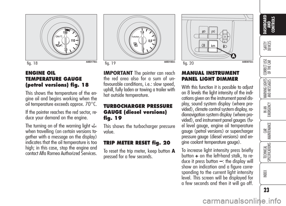
TURBOCHARGER PRESSURE
GAUGE (diesel versions)
fig. 19
This shows the turbocharger pressure
value.
TRIP METER RESET fig. 20
To reset the trip meter, keep button A
pressed for a few seconds.
MANUAL INSTRUMENT
PANEL LIGHT DIMMER
With this function it is possible to adjust
on 8 levels the light intensity of the indi-
cations given on the instrument panel dis-
play, sound system display (where pro-
vided), climate control system display, ra-
dionavigation system display (where pro-
vided), and instrument panel gauges (fu-
el level gauge, engine oil temperature
gauge (petrol versions) or supercharger
pressure gauge (diesel versions) and en-
gine coolant temperature gauge).
To increase light intensity press briefly
button+on the left-hand stalk, to re-
duce it press button –: the display will
show an indication and a figure corre-
sponding to the current light intensity
level. This screen will be displayed for
a few seconds and then it will go off.
ENGINE OIL
TEMPERATURE GAUGE
(petrol versions) fig. 18
This shows the temperature of the en-
gine oil and begins working when the
oil temperature exceeds approx. 70°C.
If the pointer reaches the red sector, re-
duce your demand on the engine.
The turning on of the warning light
`
when travelling (on certain versions to-
gether with a message on the display)
indicates that the oil temperature is too
high; in this case, stop the engine and
contact Alfa Romeo Authorized Services.
A0E0179mfig. 18A0E0180mfig. 19A0E0072mfig. 20
Page 26 of 275
24
SAFETY
DEVICES
WARNING LIGHTS
AND MESSAGES
IN AN
EMERGENCY
CAR
MAINTENANCE
TECHNICAL
SPECIFICATIONS
INDEX
DASHBOARD
AND
CONTROLS
CORRECT USE
OF THE CAR
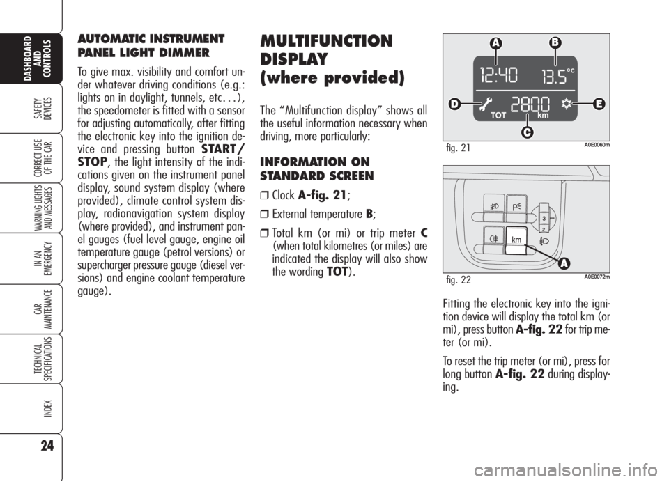
Fitting the electronic key into the igni-
tion device will display the total km (or
mi), press button A-fig. 22for trip me-
ter (or mi).
To reset the trip meter (or mi), press for
long button A-fig. 22during display-
ing.
MULTIFUNCTION
DISPLAY
(where provided)
The “Multifunction display” shows all
the useful information necessary when
driving, more particularly:
INFORMATION ON
STANDARD SCREEN
❒ClockA-fig. 21;
❒External temperature B;
❒Total km (or mi) or trip meter C
(when total kilometres (or miles) are
indicated the display will also show
the wording TOT).
A0E0060mfig. 21
A0E0072mfig. 22
AUTOMATIC INSTRUMENT
PANEL LIGHT DIMMER
To give max. visibility and comfort un-
der whatever driving conditions (e.g.:
lights on in daylight, tunnels, etc…),
the speedometer is fitted with a sensor
for adjusting automatically, after fitting
the electronic key into the ignition de-
vice and pressing button START/
STOP, the light intensity of the indi-
cations given on the instrument panel
display, sound system display (where
provided), climate control system dis-
play, radionavigation system display
(where provided), and instrument pan-
el gauges (fuel level gauge, engine oil
temperature gauge (petrol versions) or
supercharger pressure gauge (diesel ver-
sions) and engine coolant temperature
gauge).
Page 30 of 275
ENGINE OIL LEVEL
INDICATION
Fitting the electronic key into the igni-
tion device, the display will show for a
few seconds the engine oil level. At this
stage, to clear this indication and to go
to next screen, press button MENU.
Low/excessive oil level will be indicat-
ed by a dedicated warning message on
the display.
IMPORTANT Check the proper en-
gine oil level on the dipstick (see para-
graph “Checking levels” in section “Car
maintenance”).
IMPORTANTProper engine oil level
shall be checked with the car on level
ground.
IMPORTANT To read the correct oil
level after fitting the electronic key, wait
for about 2 seconds before starting the
engine.
MESSAGES DISPLAYED
AT STARTING
After the engine oil level, the display will
show for a few seconds a message in-
dicating the procedure to follow to start
the engine (PRESS PEDAL AND
START: press brake or clutch pedal and
then press button START/STOPto
start the engine). Scheduled servicing
IMPORTANTThe Service schedule in-
cludes car maintenance every 30,000
km (or 18,000 mi); this is shown au-
tomatically, with the electronic key in-
to the ignition device starting from
2,000 km (or 1,240 mi) from this
deadline and it will be displayed in km
or miles according to the unit set. When
a scheduled service interval (“coupon”)
is near to come, fitting the electronic key
into the ignition device will display a
message followed by the number of
km/mi to go before car servicing. Con-
tact Alfa Romeo Authorized Services to
carry out any service operation provid-
ed by the Service schedule or by the An-
nual inspection plan, and to reset the
display.
28
SAFETY
DEVICES
WARNING LIGHTS
AND MESSAGES
IN AN
EMERGENCY
CAR
MAINTENANCE
TECHNICAL
SPECIFICATIONS
INDEX
CORRECT USE
OF THE CAR
DASHBOARD
AND
CONTROLS
Page 35 of 275

33
SAFETY
DEVICES
WARNING LIGHTS
AND MESSAGES
IN AN
EMERGENCY
CAR
MAINTENANCE
TECHNICAL
SPECIFICATIONS
INDEX
DASHBOARD
AND
CONTROLS
CORRECT USE
OF THE CAR
Briefly press button MENUto access navigation from the standard screen. To surf the menu press buttons +or–. For safety rea-
sons, when the car is running, it is possible to access only the reduced menu (for setting “Speed limit”). When the car is stationary
access to the whole menu is enabled. With the Radionavigation system it is only possible to adjust/set the following functions: “Speed
Limit”, “Light sensor sensitivity ” (where provided) and “S.B.R. buzzer reactivation” (where provided). The other functions are shown
on the Radionavigation system display, that shall be use to adjust/set them as required.
fig. 26
BEEP VOL.SERVICEQUIT SETUPLIGHT SENS.RESET TRIP B
CLOCK
MODE 12/24
DATE
AUDIO RPT.
INDEP. BOOT
UNLOCK FDA
DOOR LOCK
UNITS KEYS VOL.
LANGUAGESPEED LIMIT
A0E0218g
Page 36 of 275

34
SAFETY
DEVICES
WARNING LIGHTS
AND MESSAGES
IN AN
EMERGENCY
CAR
MAINTENANCE
TECHNICAL
SPECIFICATIONS
INDEX
DASHBOARD
AND
CONTROLS
CORRECT USE
OF THE CAR
Automatic headlight daylight
sensor (where provided)
(Light Sens.)
With this function it is possible to adjust
the light sensor sensitivity according to
3 levels.
To adjust the volume proceed as follows:
❒briefly press button MENU: the pre-
viously set level will flash on the dis-
play;
❒press button +or–to select the re-
quired volume;
❒briefly press buttonMENUto go
back to the menu screen or press the
button for long to go back to the stan-
dard screen.
Reset Trip B
This function enables to select Trip B re-
set mode (Automatic or Manual).
For further information see paragraph
“Trip computer”. Speed limit
With this function it is possible to set the
car speed limit (km/h or mph) which,
if exceeded, automatically sounds a
buzzer and displays a special message
(see section “Warning lights and mes-
sages”) to alert the driver.
To set the speed limit, proceed as fol-
lows:
❒briefly press button MENU: the dis-
play will show OFF;
❒press button +: the display will show
ON;
❒briefly press button MENUthen, use
buttons+/–to set the required
speed (during setting the value will
flash).
❒briefly press button MENUto go
back to the menu screen or press the
button for long to go back to the stan-
dard screen.IMPORTANTThe possible setting is
between 30 and 250 km/h (or be-
tween 20 and 150 mph) depending on
the unit set previously (see paragraph
“Units” described later). Every press
(pulse) of the button +/–increases or
decreases the value by 5 units. Keeping
the button +/–pressed obtains auto-
matic fast increase or decrease. When
you are near the required setting com-
plete adjustment with single presses.
To abort the setting:
❒briefly press button MENU: the dis-
play will show ON;
❒press button –: the display will show
OFF;
❒briefly press button MENUto go
back to the menu screen or press the
button for long to go back to the stan-
dard screen.
Page 42 of 275

Reactivating the S.B.R.
(Seat Belt Reminder) buzzer
(Beep Seatb.) (where provided)
This function is displayed only after the
system has been deactivated by Alfa
Romeo Authorized Services.
Exit Menu (Quit setup)
Selecting this option will bring back to
standard screen.
REV COUNTER/DASHBOARD
BUTTON LIGHT
(NIGHT PANEL)
This function enables to turn on/off
(ON/OFF) the lights of the rev counter
and dashboard buttons. This function can
be activated (only with electronic key fit-
ted into ignition device, external lights on,
and speedometer built-in sensor in poor
outside light setting), by pressing for long
button–. When this function is on, the
display will show a warning message.
Once on, the NIGHT PANELfunction
can be deactivated as follows:
❒by long press on button +(also with
external lights off);
❒removing the electronic key from the
ignition device.
When function is off the display will show
a warning message.
Messages stay on the display for a few
seconds, then they will go off. To stop
displaying before time, briefly press but-
tonMENU. Scheduled Servicing (Service)
Through this function it is possible to dis-
play information connected to proper car
servicing.
Proceed as follows:
❒briefly press button MENU: service
in km or mi, according to previous
setting, will be displayed (see para-
graph “Units”);
❒briefly press buttonMENUto go
back to the menu screen or press the
button for long to go back to the stan-
dard screen.
IMPORTANTThe Service schedule in-
cludes car maintenance every 30,000 km
(or 18,000 mi); this is shown automat-
ically, with the electronic key into the ig-
nition device starting from 2,000 km (or
1,240 mi) from this deadline and it will
be displayed in km or miles according to
the unit set. When a scheduled service in-
terval (“coupon”) is near to come, fitting
the electronic key into the ignition device
will display a message followed by the
number of km/mi to go before car ser-
vicing. Contact Alfa Romeo Authorized Ser-
vices to carry out any service operation
provided by the Service schedule or by the
Annual inspection plan, and to reset the
display.
40
SAFETY
DEVICES
WARNING LIGHTS
AND MESSAGES
IN AN
EMERGENCY
CAR
MAINTENANCE
TECHNICAL
SPECIFICATIONS
INDEX
DASHBOARD
AND
CONTROLS
CORRECT USE
OF THE CAR
Page 43 of 275

41
SAFETY
DEVICES
WARNING LIGHTS
AND MESSAGES
IN AN
EMERGENCY
CAR
MAINTENANCE
TECHNICAL
SPECIFICATIONS
INDEX
DASHBOARD
AND
CONTROLS
CORRECT USE
OF THE CAR
Reset TRIP B
End of partial mission
Start of new partial mission End of partial mission
Start of new
partial mission
Reset TRIP B
End of partial mission
Start of new
partial mission Reset GENERAL TRIP
End of complete mission
Start of new missionReset GENERAL TRIP
End of complete mission
Start of new mission
End of partial mission
Start of new
partial mission Reset TRIP B
Reset TRIP B TRIP B
TRIP B
TRIP B GENERAL TRIP
˙
˙
˙
˙˙
˙
˙ ˙
fig. 27
TRIP COMPUTER
General features
The “Trip computer” displays information (with electronic key fitted into ignition device) relating to the operating status of
the car. This function comprises the “General trip” concerning the “complete mission” of the car (journey) and “Trip B” con-
cerning the partial mission of the car; this latter function (as shown in fig. 27) is “contained” within the complete mission.
Both functions are resettable (reset - start of new mission).
Page 44 of 275

42
SAFETY
DEVICES
WARNING LIGHTS
AND MESSAGES
IN AN
EMERGENCY
CAR
MAINTENANCE
TECHNICAL
SPECIFICATIONS
INDEX
DASHBOARD
AND
CONTROLS
CORRECT USE
OF THE CAR
Values displayed
Average consumption
This value shows the average con-
sumption from the start of the new mis-
sion.
Current consumption
This value shows instant fuel consump-
tion (this value is updated second by
second). If parking the car with engine
on, the display will show “- - - -”.
Average speed
This value shows the car average speed
as a function of the overall time elapsed
since the start of the new mission.
Travel time
This value shows the time elapsed since
the start of the new mission (driving
time).
Range
This value shows the distance in km (or
mi) that the car can still cover before
needing fuel, assuming that driving con-
ditions are kept unvaried.The display will show “- - - -“ in the fol-
lowing cases:
❒value lower than 50 km (30mi);
❒car left parked with engine running
for over 5 minutes.
Travel Distance
This value shows the distance covered
from the start of the new mission.
Each time the battery is connected and
each time a new mission is started (re-
set), the display will show “0.0”.
IMPORTANTLacking information,
Trip computer values are displayed with
“- - - -”. When normal operating condi-
tion is reset, calculation of different units
will restart regularly. Values displayed
before the failure will not be reset. The “General Trip” displays the figures
relating to:
❒Average consumption
❒Current consumption
❒Average speed
❒Travel time
❒Range
❒Travel Distance
“Trip B” displays information concern-
ing:
❒Travel Distance B
❒Average consumption B
❒Average speed B
❒Travel time B.