tow Alfa Romeo 159 2007 Owner handbook (in English)
[x] Cancel search | Manufacturer: ALFA ROMEO, Model Year: 2007, Model line: 159, Model: Alfa Romeo 159 2007Pages: 303, PDF Size: 5.2 MB
Page 154 of 303

152
SAFETY
DEVICES
WARNING
LIGHTS AND
MESSAGES
IN AN
EMERGENCY
CAR
MAINTENANCE
TECHNICAL
SPECIFICATIONS
INDEX
DASHBOARD
AND
CONTROLS
CORRECT USE
OF THE CAR
STARTING PROCEDURE FOR
PETROL VERSIONS
Proceed as follows:
❒ Ensure that the handbrake is up;
❒Put the gear lever neutral;
❒Fit the electronic key into the ignition
device to stop limit;
❒Press the clutch (or brake) pedal down
to the floor without pressing the ac-
celerator;
❒Press button START/STOPand re-
lease it as soon as the engine starts.
We recommend that
during the initial period
you do not drive to full
car performance (e.g.: excessive
acceleration, long journeys at
top speed, sharp braking, etc.).
Running the engine in
confined areas is ex-
tremely dangerous. The engine
consumes oxygen and pro-
duces carbon monoxide which
is a highly toxic and lethal gas.
WARNING
When the engine is
switched off never leave
the electronic key into the
ignition device to prevent point-
less current absorption from
draining the batter.STARTING PROCEDURE FOR
DIESEL VERSIONS
Proceed as follows:
❒Ensure that the handbrake is up;
❒Put the gear lever neutral;
❒fit the electronic key down into the
ignition device until it stops. The in-
strument panel warning light
m
will turn on;
❒Wait for the warning light mto
turn off. The hotter the engine is, the
quicker this will happen;
❒Press the clutch (or brake) pedal
down to the floor without pressing the
accelerator;
❒Press button START/STOPas soon
as warning light
mgoes out. If you
wait too long you will lose the ben-
efit of the work done by the glow
plugs. Release the button as soon as
the engine starts.
ENGINE STARTING
The car is fitted with an electronic engine
immobilising system. If the engine fails
to start, see paragraph “Alfa Romeo
CODE system” in section “Dashboard
and controls”.
IMPORTANTTampering with the ig-
nition device can cause unrequired steer-
ing lock.
IMPORTANT Fit completely the elec-
tronic key into the ignition device until
it locks into place.
IMPORTANT Never take the elec-
tronic key out of the ignition device while
the car is moving unless you have to car-
ry out an emergency removal (see para-
graph “Removing the electronic key from
the ignition device in an emergency”),
this ensures that the steering column lock
is deactivated while the car is moving
(e.g.: towing the car).
Page 159 of 303

157
SAFETY
DEVICES
WARNING
LIGHTS AND
MESSAGES
IN AN
EMERGENCY
CAR
MAINTENANCE
TECHNICAL
SPECIFICATIONS
INDEX
DASHBOARD
AND
CONTROLS
CORRECT USE
OF THE CAR
Climate control
The air conditioner is an additional load
which greatly affects the engine leading
to higher consumption. When the tem-
perature outside the car permits it, use
the air vents where possible.
Spoilers
The use of aerodynamic optional extras
which are not certified for the specific
use on the vehicle, may reduce the aero-
dynamic penetration of the vehicle and
increase consumption. Unnecessary loads
Do not travel with too much luggage
stowed in the boot. The weight of the
car (especially when driving in town)
and its trim greatly affects consumption
and stability.
Roof rack/ski rack
Remove the roof rack or the ski rack
from the roof as soon as they are no
longer used. These accessories lower air
penetration and adversely affect con-
sumption levels. When needing to car-
ry particularly voluminous objects, prefer-
ably use a trailer.
Electric devices
Use electric devices only for the amount
of time needed. Rear heated window,
additional headlights, windscreen wipers
and heater fan need a considerable
amount of energy, therefore increasing
the requirement of current increases fu-
el consumption (up to +25% in the ur-
ban cycle).CONTAINING
RUNNING COSTS
Here are some suggestions which may
help you to keep the running costs of
your car down and lower the amount of
toxic emissions released into the at-
mosphere.
GENERAL CONSIDERATIONS
Car maintenance
Have checks and adjustments carried out
in accordance with the “Service sched-
ule”.
Tyres
Check the pressure of the tyres routine-
ly at an interval of no more than 4
weeks: if the pressure is too low, con-
sumption levels increase as resistance
to rolling is higher.
Page 161 of 303

159
SAFETY
DEVICES
WARNING
LIGHTS AND
MESSAGES
IN AN
EMERGENCY
CAR
MAINTENANCE
TECHNICAL
SPECIFICATIONS
INDEX
DASHBOARD
AND
CONTROLS
CORRECT USE
OF THE CAR
Engage a low gear when driving down-
hill, rather than constantly using the
brake.
The weight the trailer exerts on the car
tow hook reduces by the same amount
the actual car loading capacity. To make
sure the maximum towable weight is
not exceeded (given in the log book)
account should be taken of the fully
laden trailer, including accessories and
personal belongings.
Do not exceed the speed limits of the
country you are driving in. In any case
do not exceed 100 km/h.TOWING TRAILERS
IMPORTANT NOTES
For towing caravans or trailers the car
must be fitted with a certified tow hook
and an adequate electric system. In-
stallation should be carried out by spe-
cialised personnel who release a special
document for circulation on the road.
Install any specific and/or additional
rear-view mirrors as specified by law.
Remember that when towing a trailer,
steep hills are harder to climb, the brak-
ing spaces increase and overtaking takes
longer depending on the overall weight.
The ABS system with
which the car may be
fitted does not control the
trailer braking system. Drive
with extreme care on slippery
roadbeds.
WARNING
Under no circumstances
should the car brake
system be altered to control
the trailer brake. The trailer
braking system must be fully
independent of the car hy-
draulic system.
WARNING
Page 162 of 303

160
SAFETY
DEVICES
WARNING
LIGHTS AND
MESSAGES
IN AN
EMERGENCY
CAR
MAINTENANCE
TECHNICAL
SPECIFICATIONS
INDEX
DASHBOARD
AND
CONTROLS
CORRECT USE
OF THE CAR
For the electric connection a unified con-
nector should be used which is gener-
ally placed on a special bracket normally
fastened to the towing device.
For the electrical connection, 7 pin
12VDC connection is to be used (CU-
NA/UNI and ISO/DIN Standards). Fol-
low the instructions provided by the car
manufacturer and/or the tow hitch man-
ufacturer.
An electric brake or other device (elec-
tric winch, etc.), if required, should be
supplied directly by the battery through
a cable with a cross section of no less
than 2.5 mm
2. In addition to the elec-
trical branches, the car’s electric system
can only be connected to the supply ca-
ble for an electric brake and to the ca-
ble for an internal light, though not
above 15W.Assembly diagram fig. 4
The tow hook structure must be fas-
tened in the points shown by the sym-
bol
Øusing a total of 8 M10 screws.
Fastening points (1) shall be fitted with
spacers with 20x4 mm diameter.
Counterplate (2) shall have 5 mm min-
imum thickness.
The counter-plates (3) shall have min.
thickness of 6 mm.
IMPORTANTIt is compulsory to fas-
ten a label (plainly visible) of suitable
size and material with the following
wording:
MAX LOAD ON BALL 75 kg
After fitting, screw holes shall be sealed
to prevent exhaust gas inlet.
IMPORTANTThe hook should be fas-
tened to the body avoiding any type of
drilling and trimming of the bumper.
INSTALLING THE TOW HOOK
The towing device should be fastened
to the body by specialised personnel ac-
cording to any additional and/or inte-
grative information supplied by the Man-
ufacturer of the device.
The towing device must meet current
regulations with reference to 94/20/EC
Directive and subsequent amendments.
For any version the towing device used
must match the towable weight of the
car on which it is to be installed.
Page 163 of 303

161
SAFETY
DEVICES
WARNING
LIGHTS AND
MESSAGES
IN AN
EMERGENCY
CAR
MAINTENANCE
TECHNICAL
SPECIFICATIONS
INDEX
DASHBOARD
AND
CONTROLS
CORRECT USE
OF THE CAR
fig. 4A0E0398m
REAR AXLE
Standard tow ball
full load
Page 171 of 303

169
SAFETY
DEVICES
IN AN
EMERGENCY
CAR
MAINTENANCE
TECHNICAL
SPECIFICATIONS
INDEX
CORRECT USE
OF THE CAR
DASHBOARD
AND
CONTROLS
WARNING
LIGHTS AND
MESSAGES
PASSENGER’S
FRONT AIR BAGS
DEACTIVATED
(amber)
The warning light (set on the front ceil-
ing light panel) turns on when passen-
ger’s front air bags, passenger’s knees
air bag (where provided) and passen-
ger’s front side bag are deactivated
through the relevant key switch (for ver-
sions/markets where applicable).
With passenger's air bags active, when
fitting the electronic key into the ignition
device the warning light will turn on for
about 4 seconds, will flash for the next
4 seconds and then it will turn off.
F
–Car heavy duty(e.g.: towing trail-
er uphill or fully laden car): decrease
speed, if the warning light stays on, stop
the car. Wait for 2 or 3 minutes leaving
the engine on and slightly accelerated to
further activate the circulation of the
coolant fluid, then switch the engine off.
IMPORTANTUnder severe use of the
car, keep the engine on and slightly ac-
celerated for few minutes before switch-
ing it off.
Warning light Ffailure
is indicated by warning
light
¬. In addition, the air bag
system will deactivate auto-
matically the passenger's front
air bag (front and side). Before
restarting contact Alfa Romeo
Authorized Services immedi-
ately to have the system
checked.
WARNING
ENGINE COOLANT
HIGH TEMPERATURE
(red)
Fitting the key into the ignition device,
the warning light (set on engine coolant
gauge) turns on but it shall go off after
a few seconds.
The warning light turns on (on certain
versions a dedicated message is dis-
played) to indicate engine overheating.
If the warning light comes on, proceed
as follows:
–Normal driving conditions: stop
the car, switch off the engine and check
whether the water level in the reservoir
is not below the MINmarl. Otherwise
wait for few seconds to allow engine
cooling, then open slowly and carefully
the cap, top up coolant and check
whether its level is falling between MIN
andMAXmarks in the reservoir. Check
visually any leak. If when restarting the
warning light comes on again, contact
Alfa Romeo Authorized Services.
u
With engine hot, do not
remove the cap: risk of
burnt.
WARNING
Page 183 of 303

181
SAFETY
DEVICES
WARNING
LIGHTS AND
MESSAGES
CAR
MAINTENANCE
TECHNICAL
SPECIFICATIONS
INDEX
CORRECT USE
OF THE CAR
DASHBOARD
AND
CONTROLS
IN AN
EMERGENCY
I I
N N
A A
N N
E E
M M
E E
R R
G G
E E
N N
C C
Y Y
JUMP STARTING ................................................ 182
IF A TYRE IS PUNCTURED .................................... 183
QUICK TYRE REPAIR KIT
FIX&GO automatic ............................................. 190
WHEN NEEDING TO CHANGE A BULB ................... 196
IF AN EXTERIOR LIGHT BURNS OUT ...................... 199
IF AN INTERIOR LIGHT BURNS OUT ....................... 205
IF A FUSE BLOWS .............................................. 209
IF THE BATTERY IS FLAT ...................................... 219
JACKING THE CAR............................................... 220
TOWING THE CAR .............................................. 221
Page 185 of 303

183
SAFETY
DEVICES
WARNING
LIGHTS AND
MESSAGES
CAR
MAINTENANCE
TECHNICAL
SPECIFICATIONS
INDEX
CORRECT USE
OF THE CAR
DASHBOARD
AND
CONTROLS
IN AN
EMERGENCY
IF A TYRE
IS PUNCTURED
For versions/markets where applicable,
the car can be equipped with the “Quick
tyre repair kit Fix&Go automatic“. Op-
erations required to change a wheel are
described in the following chapter.
As an alternative to the kit “Fix & Go
automatic”, the car can be provided (up-
on request) with space-saver spare
wheel or standard size spare wheel;
wheel changing and correct use of the
jack and space-saver spare wheel call for
some precautions as listed below.
BUMP STARTING
Never bump start the engine (by push-
ing, towing, or coasting downhill) as this
could cause fuel to flow into the catalytic
exhaust system and damage it beyond
repair.
Remember that the
brake booster and the
power steering system are not
operating until the engine is
started, a greater effort will
therefore be required to press
the brake pedal or turn the
steering wheel.
WARNING
Alert other drivers that
the car is stationary in
compliance with local regula-
tions: hazard warning lights,
warning triangle etc. Any pas-
sengers on board should leave
the car, especially if it is heav-
ily laden. Passengers should
stay away from oncoming
traffic while the wheel is be-
ing changed on. If the wheel is
being changed on a steep or
badly surfaced road, place the
wedges or other suitable ma-
terial under the wheel to stop
the car. Never start the engine
when the car is jacked up. If
you were towing a trailer, un-
couple the trailer before jack-
ing the car.
WARNING
Page 191 of 303

189
SAFETY
DEVICES
WARNING
LIGHTS AND
MESSAGES
CAR
MAINTENANCE
TECHNICAL
SPECIFICATIONS
INDEX
CORRECT USE
OF THE CAR
DASHBOARD
AND
CONTROLS
IN AN
EMERGENCY
REFITTING A
NORMAL WHEEL
Following the procedure described pre-
viously, raise the car and remove the
spare wheel.
Versions with steel rims
Proceed as follows:
❒Make sure the contact surfaces be-
tween standard wheel and hub are
clean so that the fastening bolts will not
come loose;
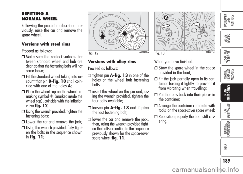
❒Fit the standard wheel taking into ac-
count that pin B-fig. 10shall coin-
cide with one of the holes A;
❒Place the wheel cap on the wheel rim
making symbol
C, (marked inside the
wheel cap), coincide with the inflation
valvefig. 12;
❒Using the wrench provided, tighten the
fastening bolts;
❒ Lower the car and remove the jack;
❒Using the wrench provided, fully tight-
en the bolts in the sequence shown
infig. 11;
A0E0211mfig. 13
Versions with alloy rims
Proceed as follows:
❒tighten pin A-fig. 13in one of the
holes of the wheel hub fastening
bolts;
❒insert the wheel on the pin and, us-
ing the wrench provided, tighten the
four bolts available;
❒loosen pin A-fig. 13and tighten
the last fastening bolt;
❒lower the car and remove the jack,
then, using the wrench provided tight-
en the bolts according to the sequence
previously shown for the space-saver
spare wheel fig. 11.When you have finished:
❒Stow the spare wheel in the space
provided in the boot;
❒Fit the jack partially open in its con-
tainer forcing it lightly to prevent it
from vibrating when travelling;
❒Put the tools back into their places in
the container;
❒Arrange the container complete with
tools on the space-saver spare wheel;
❒Reposition properly the boot stiff cov-
ering.
A0E0236mfig. 12
Page 192 of 303

190
SAFETY
DEVICES
WARNING
LIGHTS AND
MESSAGES
CAR
MAINTENANCE
TECHNICAL
SPECIFICATIONS
INDEX
CORRECT USE
OF THE CAR
DASHBOARD
AND
CONTROLS
IN AN
EMERGENCY
The quick tyre repair kit includes:
❒a bottle A-fig. 14containing the
sealer, fitted with:
- filling pipe B
- sticker Cbearing the notice “max.
80 km/h”, to be placed in a posi-
tion visible to the driver (on the in-
strument panel) after fixing the tyre;
❒compressorDwith pressure gauge
and fittings;
QUICK TYRE REPAIR
KIT FIX&GO
automatic
The car is provided with the quick tyre
repair kit “FIX&GO automatic”, instead
of the traditional tool kit and space-saver
spare wheel.
The kit fig. 14is placed in the boot. In
this container are also housed the screw-
driver and the tow hitch.
A0E0114mfig. 14A0E0048mfig. 15
❒instruction brochurefig. 15, to be
used for prompt and proper use of the
quick repair kit and to be then hand-
ed to the personnel charged with han-
dling the tyre treated with the tyre re-
pair kit;
❒a pair of protection gloves located in
the side space of the compressor;
❒adapters for inflating different ele-
ments.