sensor Alfa Romeo 159 2008 Owner handbook (in English)
[x] Cancel search | Manufacturer: ALFA ROMEO, Model Year: 2008, Model line: 159, Model: Alfa Romeo 159 2008Pages: 303, PDF Size: 5.18 MB
Page 61 of 303
59
SAFETY
DEVICES
WARNING
LIGHTS AND
MESSAGES
IN AN
EMERGENCY
CAR
MAINTENANCE
TECHNICAL
SPECIFICATIONS
INDEX
CORRECT USE
OF THE CAR
DASHBOARD
AND
CONTROLS
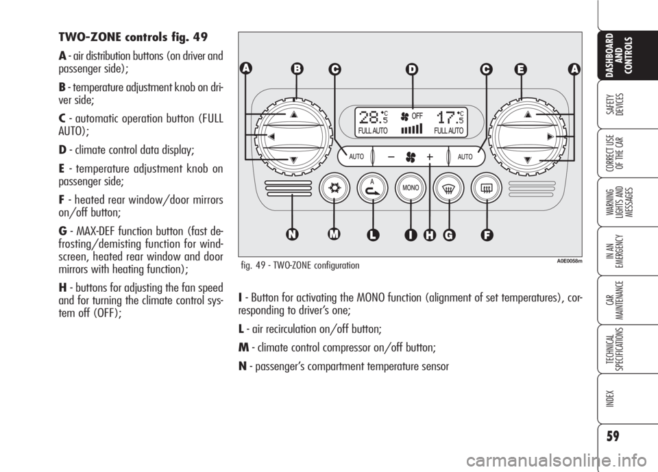
I- Button for activating the MONO function (alignment of set temperatures), cor-
responding to driver’s one;
L- air recirculation on/off button;
M- climate control compressor on/off button;
N- passenger’s compartment temperature sensor TWO-ZONE controls fig. 49
A- air distribution buttons (on driver and
passenger side);
B- temperature adjustment knob on dri-
ver side;
C- automatic operation button (FULL
AUTO);
D- climate control data display;
E- temperature adjustment knob on
passenger side;
F- heated rear window/door mirrors
on/off button;
G- MAX-DEF function button (fast de-
frosting/demisting function for wind-
screen, heated rear window and door
mirrors with heating function);
H- buttons for adjusting the fan speed
and for turning the climate control sys-
tem off (OFF);
fig. 49 - TWO-ZONE configurationA0E0058m
Page 62 of 303
60
SAFETY
DEVICES
WARNING
LIGHTS AND
MESSAGES
IN AN
EMERGENCY
CAR
MAINTENANCE
TECHNICAL
SPECIFICATIONS
INDEX
CORRECT USE
OF THE CAR
DASHBOARD
AND
CONTROLS
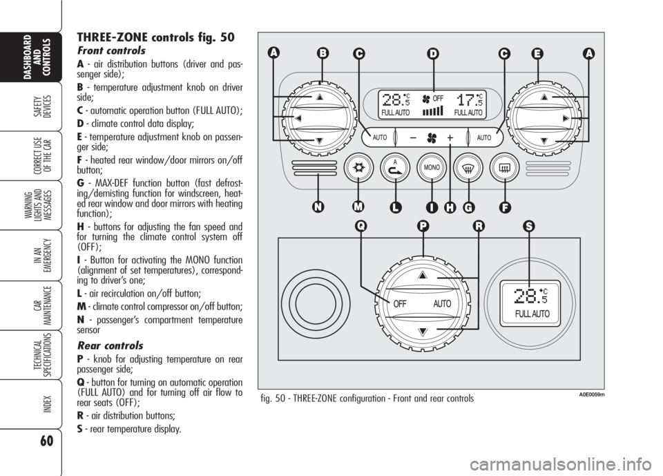
THREE-ZONE controls fig. 50
Front controls
A- air distribution buttons (driver and pas-
senger side);
B- temperature adjustment knob on driver
side;
C- automatic operation button (FULL AUTO);
D- climate control data display;
E- temperature adjustment knob on passen-
ger side;
F- heated rear window/door mirrors on/off
button;
G- MAX-DEF function button (fast defrost-
ing/demisting function for windscreen, heat-
ed rear window and door mirrors with heating
function);
H- buttons for adjusting the fan speed and
for turning the climate control system off
(OFF);
I- Button for activating the MONO function
(alignment of set temperatures), correspond-
ing to driver’s one;
L- air recirculation on/off button;
M- climate control compressor on/off button;
N- passenger’s compartment temperature
sensor
Rear controls
P- knob for adjusting temperature on rear
passenger side;
Q- button for turning on automatic operation
(FULL AUTO) and for turning off air flow to
rear seats (OFF);
R- air distribution buttons;
S- rear temperature display.
fig. 50 - THREE-ZONE configuration - Front and rear controlsA0E0059m
Page 69 of 303

67
SAFETY
DEVICES
WARNING
LIGHTS AND
MESSAGES
IN AN
EMERGENCY
CAR
MAINTENANCE
TECHNICAL
SPECIFICATIONS
INDEX
CORRECT USE
OF THE CAR
DASHBOARD
AND
CONTROLS
N˙Splitting of the air flow between
Oall vents.
Rear seat Three-zone
configuration controls
Pressing buttons
N/O(rear controls)
you can manually choose one of the 3
possible modes for air distribution to the
rear side of passenger's compartment
NAir flow to the vents on the central
console (passengers’ body).
OAir flow towards the rear lower part
of the passenger compartment. This
type of distribution allows heating of the
passenger compartment in the shortest
time by proper setting of the tempera-
ture.
NSplitting of the air flow between
Othe vents to the lower part of the
passenger compartment (warmest air)
and the rear vents (coolest air).
To restore automatic air distribution con-
trol after a manual selection, press but-
tons AUTO (front controls) or AUTO (rear
controls).
AIR RECIRCULATION AND
AQS FUNCTION (AIR
QUALITY SYSTEM)
ON/OFF (where provided)
Inside air recirculation is controlled ac-
cording to the following operating log-
ics:
❒automatic control, indicated by but-
ton led “A”;
❒forced switching on (inside air recir-
culation always on), indicated by the
turning on of the circular led around
the button;
❒forced switching off (air recirculation
always off with air inlet from the out-
side), indicated by the turning off of
the circular led around the button.
With A.Q.S. (air quality sensor - where
provided), the operating logics becomes
sequential by pressing button
v.IMPORTANTThe inside air recircula-
tion system makes it possible to reach
the required heating or cooling condi-
tions faster. It is however inadvisable to
use it on rainy/cold days as it would
considerably increase the possibility of
the windows misting inside, especially
if the climate control compressor is off.
It is advisable to turn on the inside air
recirculation system in queues or tunnels
to avoid admitting polluted air from out-
side. The prolonged use of this function
should however be avoided, especially
with several persons on board, to avoid
the possibility of the windows misting
inside and to guarantee the required
fresh air inlet.
Page 73 of 303
71
SAFETY
DEVICES
WARNING
LIGHTS AND
MESSAGES
IN AN
EMERGENCY
CAR
MAINTENANCE
TECHNICAL
SPECIFICATIONS
INDEX
CORRECT USE
OF THE CAR
DASHBOARD
AND
CONTROLS
“FOLLOW ME HOME”
DEVICE
This function allows the illumination of
the space in front of the car for a pre-
set period of time.
Activation
Pull the stalk towards the steering wheel
within 2 minutes from when the engine
is turned off.
At each single movement of the stalk,
the staying on of the lights is extended
by 30 seconds up to a maximum of 3.5
minutes; then the lights are switched off
automatically.
Each time the stalk is operated, the
3
warning light turns on together with the
message on the display (see section
“Warning lights and messages”).
Deactivation
Keep the stalk pulled towards the steer-
ing wheel for more than 2 seconds.
AUTOMATIC HEADLIGHTS
SENSOR (daylight sensor)
(where provided)
It detects the changes of the external
light intensity of the car according to the
light sensitivity set: the greater the sen-
sitivity is, the smaller the amount of ex-
ternal light necessary to control the
switching-on of the external headlights
will be.
On certain versions, the daylight sen-
sor sensitivity can be adjusted through
the “Setup Menu” of the display (see
section “Reconfigurable multifunction
display” in this section).
Activation
Turn the knurled ring A-fig. 51to
2A:
in this way, the automatic activation of
the side/taillights and dipped beam
headlights is simultaneously enabled ac-
cording to outside brightness.
With lights switched on automatically
and in the presence of a switching off
control by the sensor, the main beams
will be switched off first and a few sec-
onds after also the sidelights.Deactivation
As a result of the sensor control, the
dipped beam headlights will switch off
and, after a few seconds, sidelights will
switch off too. The sensor is not able
to detect the fog presence, under this
condition lights shall therefore be
switched on manually.
Failure warnings
On certain versions headlight sensor fail-
ure is shown by the instrument panel
warning light
1, whereas on other ver-
sions a dedicated message is shown on
the display (see section “Warning lights
and messages”).
Page 76 of 303
74
SAFETY
DEVICES
WARNING
LIGHTS AND
MESSAGES
IN AN
EMERGENCY
CAR
MAINTENANCE
TECHNICAL
SPECIFICATIONS
INDEX
CORRECT USE
OF THE CAR
DASHBOARD
AND
CONTROLS
Turning the knurled ringA-fig. 54it
is possible to increase the sensitivity of
the rain sensor, obtaining a quicker
change from stationary (no wiping)
when the windscreen is dry, to first con-
tinuous speed (continuous, slow). A fur-
ther stroke will confirm operation.
Operating the windscreen washer with
the rain sensor activated (stalk at posi-
tion1-fig. 54) the normal washing
cycle is performed at the end of which
the rain sensor resumes its normal au-
tomatic function.
Removing the electronic key from the
ignition device, the rain sensor is deac-
tivated and the next time the engine is
started it will not be reactivated even if
the stalk has remained in position 1-
fig. 54. In this case to activate the rain
sensor, simply move the stalk to 0or2
and then back to 1.
When the rain sensor is reactivated in
this way, the wiper performs one stroke,
even if the windscreen is dry, to indicate
that reactivation has occurred. “Smart washing” function
Pulling the lever towards the steering
wheel (unstable position) operates the
windscreen washer.
Keeping the stalk pulled with just one
movement it is possible to operate the
washer jet and the wiper at the same
time; the wiper actually comes into op-
eration automatically when the stalk is
pulled for more than half a second.
The wiper stops working 3 strokes after
releasing the stalk; a further stroke af-
ter about 6 seconds will complete the
wiping operation.
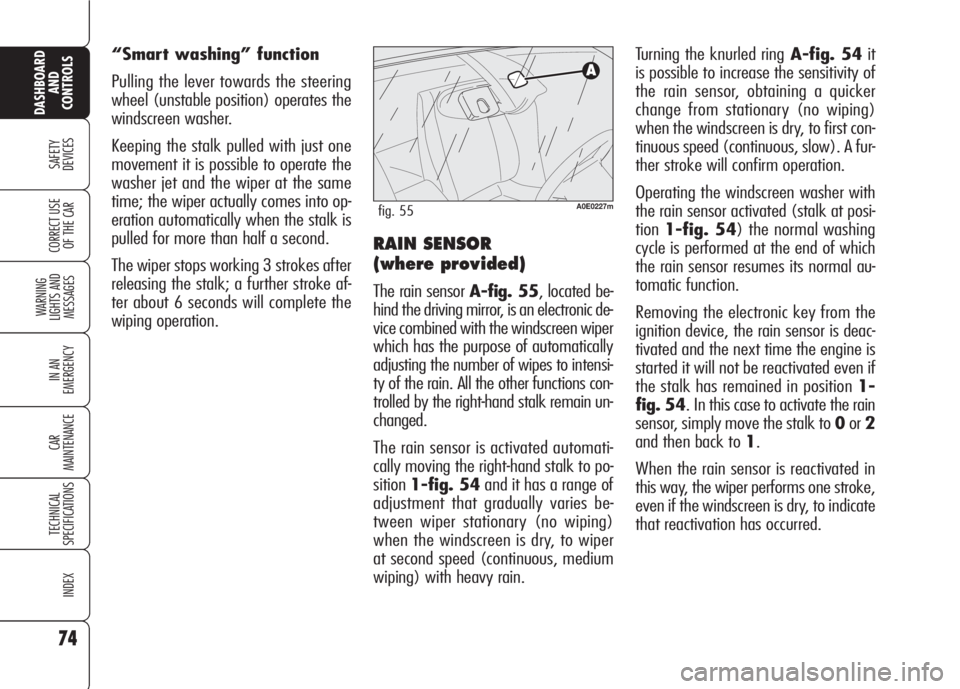
RAIN SENSOR
(where provided)
The rain sensor A-fig. 55, located be-
hind the driving mirror, is an electronic de-
vice combined with the windscreen wiper
which has the purpose of automatically
adjusting the number of wipes to intensi-
ty of the rain. All the other functions con-
trolled by the right-hand stalk remain un-
changed.
The rain sensor is activated automati-
cally moving the right-hand stalk to po-
sition1-fig. 54and it has a range of
adjustment that gradually varies be-
tween wiper stationary (no wiping)
when the windscreen is dry, to wiper
at second speed (continuous, medium
wiping) with heavy rain.
A0E0227mfig. 55
Page 77 of 303

75
SAFETY
DEVICES
WARNING
LIGHTS AND
MESSAGES
IN AN
EMERGENCY
CAR
MAINTENANCE
TECHNICAL
SPECIFICATIONS
INDEX
CORRECT USE
OF THE CAR
DASHBOARD
AND
CONTROLS
HEADLIGHT WASHERS
(where provided) fig. 56
Headlight washers are visible and are fit-
ted with a nozzle for each external light
function. They come into operation au-
tomatically when operating the wind-
screen washer with external lights
turned on.
IMPORTANT Check at regular inter-
vals correct operation and cleanness of
nozzles. IMPORTANT In the event of rain sen-
sor failure, windscreen wiper operation
with right-hand stalk at 1-fig. 54shall
be intermittent. If failure occurs during
automatic operation, the system will
keep the last wiper operating condition.
Operation is however guaranteed al-
though moving the stalk to other posi-
tions.
The rain sensor is able to recognize and
automatically adjust itself in the pres-
ence of the following particular condi-
tions:
❒ impurities on the controlled surface
(salt, dirt, etc.);
❒difference between day and night.
Failure warnings
On certain versions rain sensor failure is
shown by the instrument panel warning
light
u, whereas on other versions a
dedicated message is shown on the dis-
play (see section “Warning lights and
messages”).
Rain sensor shall be de-
activated when washing
the car at automatic car-
wash.
Make sure the rain sen-
sor is deactivated if
there is ice on the wind-
screen.
Make sure the device is
off when cleaning the
windscreen.
WARNING
A0E0046mfig. 56
Streaks of water could
cause unrequired blade
movements.
Page 104 of 303
102
SAFETY
DEVICES
WARNING
LIGHTS AND
MESSAGES
IN AN
EMERGENCY
CAR
MAINTENANCE
TECHNICAL
SPECIFICATIONS
INDEX
CORRECT USE
OF THE CAR
DASHBOARD
AND
CONTROLS
OPENING BY REMOTE
CONTROL
Press the electronic key button `.
Opening is indicated by double flashing
of direction indicators.
Opening the boot with alarm (where
provided) on will cause the following:
❒volumetric protection deactivation;
❒anti-raising protection deactivation;
❒tailgate monitoring sensor.
Re-closing the tailgate will restore all the
above functions and direction indicators
will turn on for about 1 second. Emergency opening of the
boot from the passenger
compartment (foreseen only
on the 3-volume saloon
version)
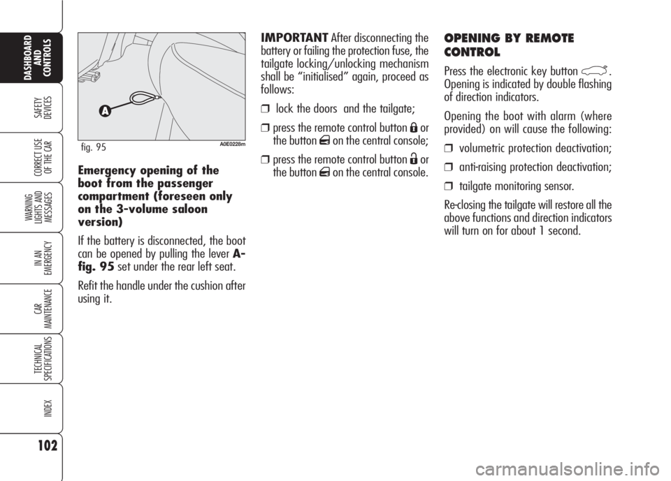
If the battery is disconnected, the boot
can be opened by pulling the lever A-
fig. 95set under the rear left seat.
Refit the handle under the cushion after
using it.
A0E0228mfig. 95
IMPORTANTAfter disconnecting the
battery or failing the protection fuse, the
tailgate locking/unlocking mechanism
shall be “initialised” again, proceed as
follows:
❒lock the doors and the tailgate;
❒press the remote control button Áor
the button
qon the central console;
❒press the remote control button Ëor
the button
qon the central console.
Page 120 of 303
118
SAFETY
DEVICES
WARNING
LIGHTS AND
MESSAGES
IN AN
EMERGENCY
CAR
MAINTENANCE
TECHNICAL
SPECIFICATIONS
INDEX
CORRECT USE
OF THE CAR
DASHBOARD
AND
CONTROLS
PARKING SENSORS
(where provided)
Parking sensors inform the driver about
the presence of obstacles behind the car
(versions fitted with 4 rear sensors) or
behind and in front of the car (versions
fitted with 4 rear sensors and 4 front
sensors).
This system is therefore an aid for the
driver when parking the car since it de-
tects obstacles out of the driver’s sight
range.
The presence and the distance from the
car of an obstacle is indicated by a warn-
ing buzzer - as the distance from the ob-
stacle decreases, the acoustic alarm be-
comes more frequent - and, only on cer-
tain versions, by an image on the dis-
play (see paragraph “Indications on the
display).
A0E0087mfig. 104
ACTIVATION
Versions with 4 sensors
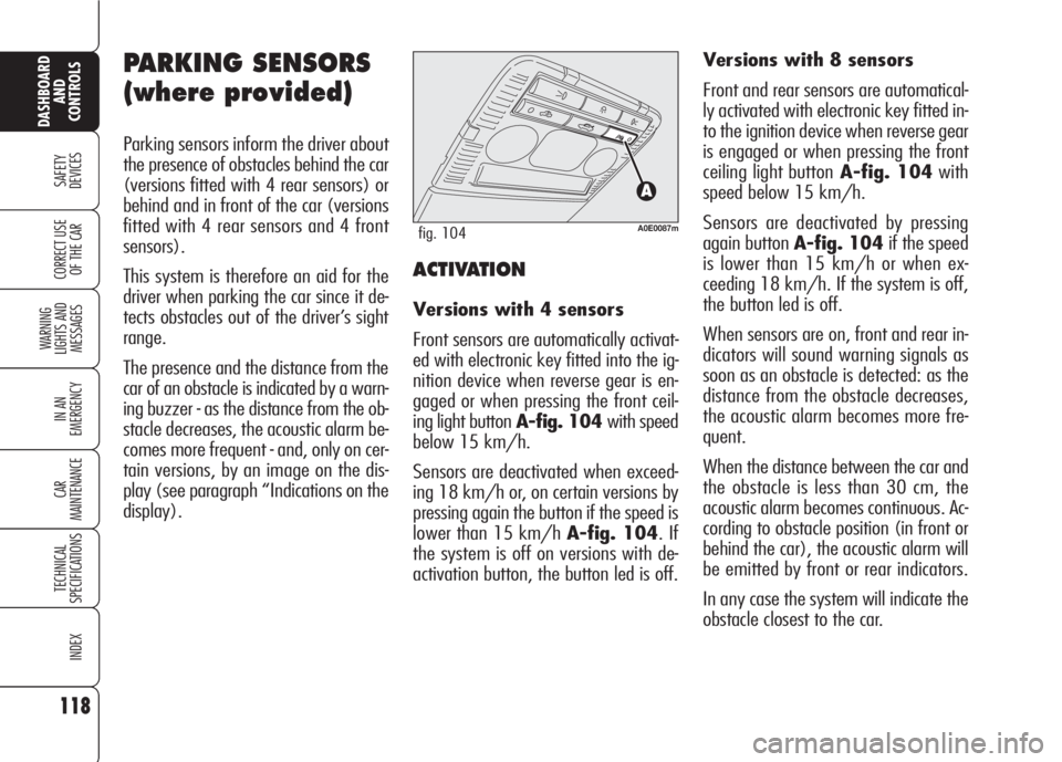
Front sensors are automatically activat-
ed with electronic key fitted into the ig-
nition device when reverse gear is en-
gaged or when pressing the front ceil-
ing light button A-fig. 104 with speed
below 15 km/h.
Sensors are deactivated when exceed-
ing 18 km/h or, on certain versions by
pressing again the button if the speed is
lower than 15 km/h A-fig. 104. If
the system is off on versions with de-
activation button, the button led is off.Versions with 8 sensors
Front and rear sensors are automatical-
ly activated with electronic key fitted in-
to the ignition device when reverse gear
is engaged or when pressing the front
ceiling light buttonA-fig. 104with
speed below 15 km/h.
Sensors are deactivated by pressing
again button A-fig. 104if the speed
is lower than 15 km/h or when ex-
ceeding 18 km/h. If the system is off,
the button led is off.
When sensors are on, front and rear in-
dicators will sound warning signals as
soon as an obstacle is detected: as the
distance from the obstacle decreases,
the acoustic alarm becomes more fre-
quent.
When the distance between the car and
the obstacle is less than 30 cm, the
acoustic alarm becomes continuous. Ac-
cording to obstacle position (in front or
behind the car), the acoustic alarm will
be emitted by front or rear indicators.
In any case the system will indicate the
obstacle closest to the car.
Page 121 of 303
119
SAFETY
DEVICES
WARNING
LIGHTS AND
MESSAGES
IN AN
EMERGENCY
CAR
MAINTENANCE
TECHNICAL
SPECIFICATIONS
INDEX
CORRECT USE
OF THE CAR
DASHBOARD
AND
CONTROLS
The acoustic alarm will stop immediately
as distance raises. The acoustic alarm is
constant if the distance measured by
central sensors is unvaried, whereas if
this situation takes place for side sen-
sors the acoustic alarm is muted after
about 3 seconds to prevent sound indi-
cations when performing manoeuvres
near walls.
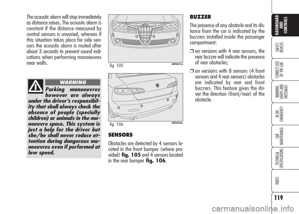
SENSORS
Obstacles are detected by 4 sensors lo-
cated in the front bumper (where pro-
vided)fig. 105and 4 sensors located
in the rear bumperfig. 106.
Parking manoeuvres
however are always
under the driver’s responsibil-
ity that shall always check the
absence of people (specially
children) or animals in the ma-
noeuvre space. This system is
just a help for the driver but
she/he shall never reduce at-
tention during dangerous ma-
noeuvres even if performed at
low speed.
WARNING
A0E0231mfig. 105
A0E0232mfig. 106
BUZZER
The presence of any obstacle and its dis-
tance from the car is indicated by the
buzzers installed inside the passenger
compartment:
❒on versions with 4 rear sensors, the
rear buzzer will indicate the presence
of rear obstacles;
❒on versions with 8 sensors (4 front
sensors and 4 rear sensors) obstacles
are indicated by rear and front
buzzers. This feature gives the dri-
ver the direction (front/rear) of the
obstacle.
Page 122 of 303

120
SAFETY
DEVICES
WARNING
LIGHTS AND
MESSAGES
IN AN
EMERGENCY
CAR
MAINTENANCE
TECHNICAL
SPECIFICATIONS
INDEX
CORRECT USE
OF THE CAR
DASHBOARD
AND
CONTROLS
SENSOR DETECTION
RANGE
Sensors enable the system to monitor
the front part (versions with 8 sensors)
and the rear part of the car.
Actually their position covers the central
and side areas of the front and rear part
of the car.
An obstacle positioned at central area is
detected at a distance less than 0.9 m
(front) and 1.40 m (rear).
An obstacle positioned at side area is de-
tected at a distance less than 0.6 m.
For proper operation,
the parking sensors shall
always be clean from
mud, dirt, snow or ice. When
cleaning the sensors, take the
utmost care to prevent their
damaging; do not use therefore
dry or rough clothes. Sensors
shall be washed with clean wa-
ter and car detergent, if re-
quired. In washing stations,
clean sensors quickly keeping
the vapour jet/high pressure
washing nozzles at 10 cm at
least from the sensors.
Repainting the bumpers
or touch-up in the sen-
sor area, if required,
shall be carried out at Alfa
Romeo Authorized Services on-
ly. Incorrect repainting may im-
pair regular operation of the
parking sensors.
INDICATIONS ON THE
DISPLAY (where provided)
On versions with 8 sensors, sensor acti-
vation is indicated on the “Reconfig-
urable multifunction display” (where pro-
vided) by screen fig.107; therefore ob-
stacle presence and distance is indicated
(in addition to buzzer) also on the in-
strument panel display.
In the event of several obstacles, the ob-
stacle closest to the car will be indicat-
ed.
A0E0239mfig. 107