sensor Alfa Romeo 159 2008 Owner handbook (in English)
[x] Cancel search | Manufacturer: ALFA ROMEO, Model Year: 2008, Model line: 159, Model: Alfa Romeo 159 2008Pages: 303, PDF Size: 5.18 MB
Page 8 of 303
6
SAFETY
DEVICES
WARNING
LIGHTS AND
MESSAGES
IN AN
EMERGENCY
CAR
MAINTENANCE
TECHNICAL
SPECIFICATIONS
INDEX
CORRECT USE
OF THE CAR
DASHBOARD
AND
CONTROLS
D D
A A
S S
H H
B B
O O
A A
R R
D D
A A
N N
D D
C C
O O
N N
T T
R R
O O
L L
S S
CRUISE CONTROL .............................................. 76
CEILING LIGHTS ................................................. 78
CONTROLS ........................................................ 81
INTERIOR FITTINGS............................................. 83
SUNROOF ......................................................... 93
DOORS ............................................................ 96
POWER WINDOWS ............................................ 99
BOOT ............................................................... 101
BONNET............................................................ 105
ROOF RACK/SKI RACK ....................................... 106
HEADLIGHTS...................................................... 106
ABS SYSTEM .................................................... 108
VDC SYSTEM .................................................... 110
EOBD SYSTEM .................................................. 115
SOUND SYSTEM PRESETTING .............................. 116
ACCESSORIES PURCHASED BY THE OWNER .......... 117
INSTALLATION OF ELECTRIC/ELECTRONIC DEVICES .. 117
PARKING SENSORS ............................................ 118
TYRE PRESSURE MONITORING SYSTEM
(T.P.M.S.) ......................................................... 122
AT THE FILLING STATION ..................................... 125
PROTECTING THE ENVIRONMENT ......................... 127 DASHBOARD...................................................... 7
INSTRUMENT PANEL .......................................... 8
SYMBOLS ........................................................ 10
ALFA ROMEO CODE SYSTEM ................................ 10
ELECTRONIC KEY ............................................... 12
ALARM ............................................................ 17
IGNITION DEVICE................................................ 19
INSTRUMENTS ................................................... 21
MULTIFUNCTION DISPLAY .................................... 25
RECONFIGURABLE MULTIFUNCTION DISPLAY .......... 30
SEATS .............................................................. 45
HEAD RESTRAINTS.............................................. 48
STEERING WHEEL .............................................. 49
REARVIEW MIRRORS .......................................... 50
CLIMATE CONTROL SYSTEM ................................ 53
MANUAL CLIMATE CONTROL SYSTEM ................... 55
AUTOMATIC TWO-/THREE-ZONE
CLIMATE CONTROL SYSTEM ................................ 58
ADDITIONAL HEATER .......................................... 69
EXTERNAL LIGHTS .............................................. 70
WINDOW WASHING .......................................... 73
Page 15 of 303
13
SAFETY
DEVICES
WARNING LIGHTS
AND MESSAGES
IN AN
EMERGENCY
CAR
MAINTENANCE
TECHNICAL
SPECIFICATIONS
INDEX
DASHBOARD
AND
CONTROLS
CORRECT USE
OF THE CAR
IMPORTANT Never expose the elec-
tronic key to direct sunlight: risk of dam-
ages.
IMPORTANTRemote control fre-
quency may be disturbed by radio trans-
missions outside the car (e.g. mobile
phones, hams, etc…). In this event re-
mote control may be failing.
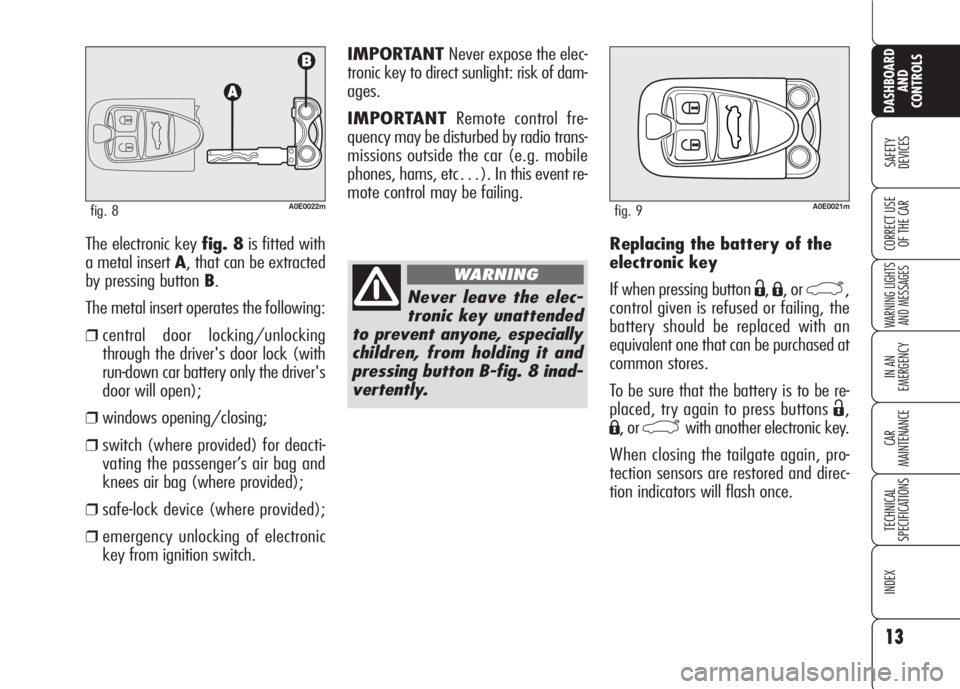
The electronic key fig. 8is fitted with
a metal insert A, that can be extracted
by pressing button B.
The metal insert operates the following:
❒central door locking/unlocking
through the driver's door lock (with
run-down car battery only the driver's
door will open);
❒windows opening/closing;
❒switch (where provided) for deacti-
vating the passenger’s air bag and
knees air bag (where provided);
❒safe-lock device (where provided);
❒emergency unlocking of electronic
key from ignition switch.Replacing the battery of the
electronic key
If when pressing button
Ë,Á, or `,
control given is refused or failing, the
battery should be replaced with an
equivalent one that can be purchased at
common stores.
To be sure that the battery is to be re-
placed, try again to press buttons
Ë,
Á, or `with another electronic key.
When closing the tailgate again, pro-
tection sensors are restored and direc-
tion indicators will flash once.
A0E0022mfig. 8
Never leave the elec-
tronic key unattended
to prevent anyone, especially
children, from holding it and
pressing button B-fig. 8 inad-
vertently.
WARNING
A0E0021mfig. 9
Page 19 of 303
17
SAFETY
DEVICES
WARNING LIGHTS
AND MESSAGES
IN AN
EMERGENCY
CAR
MAINTENANCE
TECHNICAL
SPECIFICATIONS
INDEX
DASHBOARD
AND
CONTROLS
CORRECT USE
OF THE CAR
Depending on the markets, the trigger-
ing of the alarm will activate the siren
and the hazard warning lights (for about
26 seconds). The methods of operation
and the number of cycles may vary de-
pending on the versions/markets.
A maximum number of sound/sight cy-
cles is however envisaged. Once the
alarm cycle is over, the system will re-
store its normal operation.
IMPORTANTCentral door unlocking
by the emergency electronic key will not
deactivate the alarm, therefore with
alarm on the siren will activate when
opening one of the doors or the boot.
To deactivate the siren see paragraph
“How to deactivate the alarm”.
IMPORTANTThe engine immobiliser
function is guaranteed by the Alfa
Romeo CODE system, which is auto-
matically activated when the electronic
key is removed from the ignition device.
HOW TO ACTIVATE
THE ALARM
With the doors, bonnet and boot shut
and electronic key removed from igni-
tion switch, point the electronic key in
the direction of the car, then press and
release the button
Á.
With the exception of certain markets,
the system sounds a “beep” and the
doors are locked.
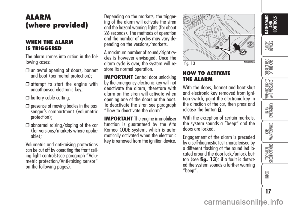
Engagement of the alarm is preceded
by a self-diagnostic test characterised by
a different flashing of the round led lo-
cated around the door lock/unlock but-
ton (see fig. 13): if a fault is detect-
ed the system sounds a further warning
“beep”.
ALARM
(where provided)
WHEN THE ALARM
IS TRIGGERED
The alarm comes into action in the fol-
lowing cases:
❒unlawful opening of doors, bonnet
and boot (perimetral protection);
❒attempt to start the engine with
unauthorised electronic key;
❒ battery cable cutting;
❒ presence of moving bodies in the pas-
senger’s compartment (volumetric
protection);
❒abnormal raising/sloping of the car
(for versions/markets where applic-
able);
Volumetric and anti-raising protections
can be cut off by operating the front ceil-
ing light controls(see paragraph “Volu-
metric protection/Anti-raising sensor”
on the following pages).
A0E0025mfig. 13
Page 20 of 303
HOW TO DEACTIVATE
THE ALARM
Press button Ë. The system will react as
follows (with the exception of certain
markets):
❒two brief flashes of the direction in-
dicators;
❒two brief “beeps”;
❒door unlocking.
The alarm can be deactivated by fitting
the electronic key into the ignition
switch.
IMPORTANTOn certain versions any
attempt to break in detected by the sys-
tem will be indicated by a warning mes-
sage on the instrument panel display
when fitting the electronic key into the
ignition switch.VOLUMETRIC PROTECTION/
ANTI-RAISING SENSORS
To make sure that the protection sensors
are working properly, check that win-
dows and sunroof (where provided) are
shut.
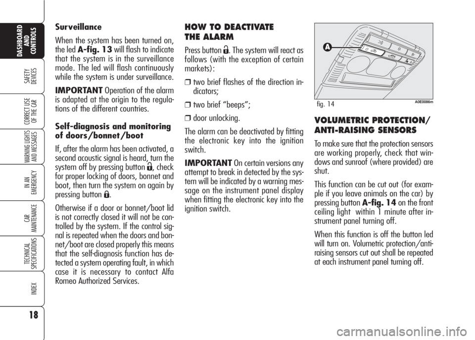
This function can be cut out (for exam-
ple if you leave animals on the car) by
pressing button A-fig. 14on the front
ceiling light within 1 minute after in-
strument panel turning off.
When this function is off the button led
will turn on. Volumetric protection/anti-
raising sensors cut out shall be repeated
at each instrument panel turning off. Surveillance
When the system has been turned on,
the led A-fig. 13will flash to indicate
that the system is in the surveillance
mode. The led will flash continuously
while the system is under surveillance.
IMPORTANTOperation of the alarm
is adapted at the origin to the regula-
tions of the different countries.
Self-diagnosis and monitoring
of doors/bonnet/boot
If, after the alarm has been activated, a
second acoustic signal is heard, turn the
system off by pressing button
Ë, check
for proper locking of doors, bonnet and
boot, then turn the system on again by
pressing button
Á.
Otherwise if a door or bonnet/boot lid
is not correctly closed it will not be con-
trolled by the system. If the control sig-
nal is repeated when the doors and bon-
net/boot are closed properly this means
that the self-diagnosis function has de-
tected a system operating fault, in which
case it is necessary to contact Alfa
Romeo Authorized Services.
18
SAFETY
DEVICES
WARNING LIGHTS
AND MESSAGES
IN AN
EMERGENCY
CAR
MAINTENANCE
TECHNICAL
SPECIFICATIONS
INDEX
DASHBOARD
AND
CONTROLS
CORRECT USE
OF THE CAR
A0E0086mfig. 14
Page 26 of 303
24
SAFETY
DEVICES
WARNING LIGHTS
AND MESSAGES
IN AN
EMERGENCY
CAR
MAINTENANCE
TECHNICAL
SPECIFICATIONS
INDEX
DASHBOARD
AND
CONTROLS
CORRECT USE
OF THE CAR
AUTOMATIC INSTRUMENT
PANEL LIGHT DIMMER
To give max. visibility and comfort un-
der whatever driving conditions (e.g.:
lights on in daylight, tunnels, etc…),
the speedometer is fitted with a sensor
for adjusting automatically, after fitting
the electronic key into the ignition de-
vice and pressing button START/
STOP, the light intensity of the indi-
cations given on the instrument panel
display, sound system display (where
provided), climate control system dis-
play, radionavigation system display
(where provided), and instrument pan-
el gauges (fuel level gauge, engine oil
temperature gauge (petrol versions) or
supercharger pressure gauge (diesel ver-
sions) and engine coolant temperature
gauge).
MANUAL INSTRUMENT
PANEL LIGHT DIMMER
With this function it is possible to adjust
on 8 levels the light intensity of the indi-
cations given on the instrument panel dis-
play, sound system display (where pro-
vided), climate control system display, ra-
dionavigation system display (where pro-
vided), and instrument panel gauges (fu-
el level gauge, engine oil temperature
gauge (petrol versions) or supercharger
pressure gauge (diesel versions) and en-
gine coolant temperature gauge).
To increase light intensity press briefly
button+on the left-hand stalk, to re-
duce it press button –: the display will
show an indication and a figure corre-
sponding to the current light intensity
level. This screen will be displayed for
a few seconds and then it will go off.
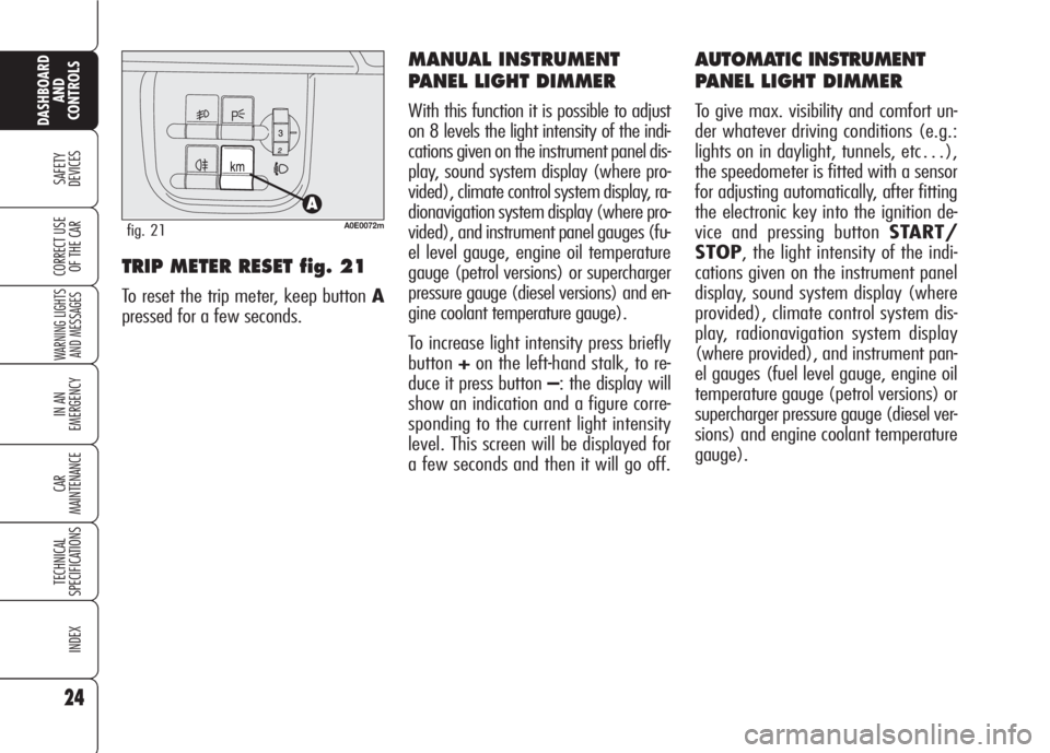
TRIP METER RESET fig. 21
To reset the trip meter, keep button A
pressed for a few seconds.
A0E0072mfig. 21
Page 31 of 303
MESSAGES DISPLAYED
AT STARTING
After the engine oil level, the display will
show for a few seconds a message in-
dicating the procedure to follow to start
the engine (PRESS PEDAL AND
START: press brake or clutch pedal and
then press button START/STOPto
start the engine).Once on, the NIGHT PANfunction
can be deactivated as follows:❒by long press on button +(also with
external lights off);
❒removing the electronic key from the
ignition device.
When this function is off the display
shows “NIGHT PAN OFF”.
Messages “NIGHT PAN ON” or
“NIGHT PAN OFF” stay on the dis-
play for a few seconds, then they will
go off. To stop displaying before time,
briefly press button MENU.
ILLUMINATION OF REV
COUNTER/INSTRUMENTS
(NIGHT PAN)
This function enables to turn on/off
(ON/OFF) the lights of the rev
counter and instruments.
This function can be activated (only with
electronic key fitted into ignition device,
external lights on, and speedometer
built-in sensor in poor outside light set-
ting), by pressing for long button –.
When this function is on, the display will
show “NIGHT PAN ON”.
29
SAFETY
DEVICES
WARNING LIGHTS
AND MESSAGES
IN AN
EMERGENCY
CAR
MAINTENANCE
TECHNICAL
SPECIFICATIONS
INDEX
CORRECT USE
OF THE CAR
DASHBOARD
AND
CONTROLS
Page 35 of 303
33
SAFETY
DEVICES
WARNING LIGHTS
AND MESSAGES
IN AN
EMERGENCY
CAR
MAINTENANCE
TECHNICAL
SPECIFICATIONS
INDEX
DASHBOARD
AND
CONTROLS
CORRECT USE
OF THE CAR
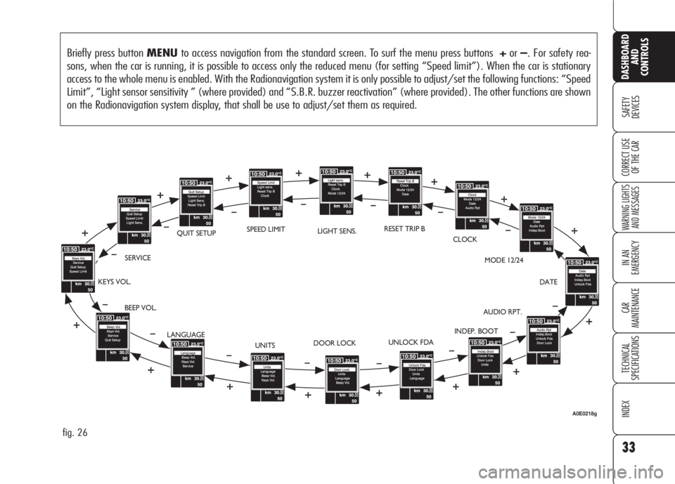
Briefly press button MENUto access navigation from the standard screen. To surf the menu press buttons +or–. For safety rea-
sons, when the car is running, it is possible to access only the reduced menu (for setting “Speed limit”). When the car is stationary
access to the whole menu is enabled. With the Radionavigation system it is only possible to adjust/set the following functions: “Speed
Limit”, “Light sensor sensitivity ” (where provided) and “S.B.R. buzzer reactivation” (where provided). The other functions are shown
on the Radionavigation system display, that shall be use to adjust/set them as required.
fig. 26
BEEP VOL.SERVICEQUIT SETUPLIGHT SENS.RESET TRIP B
CLOCK
MODE 12/24
DATE
AUDIO RPT.
INDEP. BOOT
UNLOCK FDA
DOOR LOCK
UNITS KEYS VOL.
LANGUAGESPEED LIMIT
A0E0218g
Page 36 of 303
34
SAFETY
DEVICES
WARNING LIGHTS
AND MESSAGES
IN AN
EMERGENCY
CAR
MAINTENANCE
TECHNICAL
SPECIFICATIONS
INDEX
DASHBOARD
AND
CONTROLS
CORRECT USE
OF THE CAR
Automatic headlight daylight
sensor (where provided)
(Light Sens.)
With this function it is possible to adjust
the light sensor sensitivity according to
3 levels.
To adjust the volume proceed as follows:
❒briefly press button MENU: the pre-
viously set level will flash on the dis-
play;
❒press button +or–to select the re-
quired volume;
❒briefly press buttonMENUto go
back to the menu screen or press the
button for long to go back to the stan-
dard screen.
Reset Trip B
This function enables to select Trip B re-
set mode (Automatic or Manual).
For further information see paragraph
“Trip computer”. Speed limit
With this function it is possible to set the
car speed limit (km/h or mph) which,
if exceeded, automatically sounds a
buzzer and displays a special message
(see section “Warning lights and mes-
sages”) to alert the driver.
To set the speed limit, proceed as fol-
lows:
❒briefly press button MENU: the dis-
play will show OFF;
❒press button +: the display will show
ON;
❒briefly press button MENUthen, use
buttons+/–to set the required
speed (during setting the value will
flash).
❒briefly press button MENUto go
back to the menu screen or press the
button for long to go back to the stan-
dard screen.IMPORTANTThe possible setting is
between 30 and 250 km/h (or be-
tween 20 and 150 mph) depending on
the unit set previously (see paragraph
“Units” described later). Every press
(pulse) of the button +/–increases or
decreases the value by 5 units. Keeping
the button +/–pressed obtains auto-
matic fast increase or decrease. When
you are near the required setting com-
plete adjustment with single presses.
To abort the setting:
❒briefly press button MENU: the dis-
play will show ON;
❒press button –: the display will show
OFF;
❒briefly press button MENUto go
back to the menu screen or press the
button for long to go back to the stan-
dard screen.
Page 42 of 303
Reactivating the S.B.R.
(Seat Belt Reminder) buzzer
(Beep Seatb.) (where provided)
This function is displayed only after the
system has been deactivated by Alfa
Romeo Authorized Services.
Exit Menu (Quit setup)
Selecting this option will bring back to
standard screen.
ILLUMINATION OF REV
COUNTER/INSTRUMENTS
(NIGHT PANEL)
This function enables to turn on/off
(ON/OFF) the lights of the rev counter
and instruments. This function can be ac-
tivated (only with electronic key fitted in-
to ignition device, external lights on, and
speedometer built-in sensor in poor out-
side light setting), by pressing for long but-
ton–. When this function is on, the dis-
play will show a warning message. Once
on, the NIGHT PANELfunction can be
deactivated as follows:
❒by long press on button +(also with
external lights off);
❒removing the electronic key from the
ignition device.
When function is off the display will show
a warning message.
Messages stay on the display for a few
seconds, then they will go off. To stop
displaying before time, briefly press but-
tonMENU. Scheduled Servicing (Service)
Through this function it is possible to dis-
play information connected to proper car
servicing.
Proceed as follows:
❒briefly press button MENU: service
in km or mi, according to previous
setting, will be displayed (see para-
graph “Units”);
❒briefly press buttonMENUto go
back to the menu screen or press the
button for long to go back to the stan-
dard screen.
IMPORTANTThe Service schedule in-
cludes car maintenance every 30,000 km
(or 18,000 mi); this is shown automat-
ically, with the electronic key into the ig-
nition device starting from 2,000 km (or
1,240 mi) from this deadline and it will
be displayed in km or miles according to
the unit set. When a scheduled service in-
terval (“coupon”) is near to come, fitting
the electronic key into the ignition device
will display a message followed by the
number of km/mi to go before car ser-
vicing. Contact Alfa Romeo Authorized Ser-
vices to carry out any service operation
provided by the Service schedule or by the
Annual inspection plan, and to reset the
display.
40
SAFETY
DEVICES
WARNING LIGHTS
AND MESSAGES
IN AN
EMERGENCY
CAR
MAINTENANCE
TECHNICAL
SPECIFICATIONS
INDEX
DASHBOARD
AND
CONTROLS
CORRECT USE
OF THE CAR
Page 60 of 303

58
SAFETY
DEVICES
WARNING
LIGHTS AND
MESSAGES
IN AN
EMERGENCY
CAR
MAINTENANCE
TECHNICAL
SPECIFICATIONS
INDEX
CORRECT USE
OF THE CAR
DASHBOARD
AND
CONTROLS
To guarantee perfect
and regular sensor op-
eration do not apply
stickers in the “monitoring”
area between sensor and wind-
screen. Keep windscreen and
sensor clean and avoid to accu-
mulate dust or other sub-
stances.
AUTOMATIC TWO-/
THREE-ZONE
CLIMATE CONTROL
SYSTEM
(where provided)
DESCRIPTION
The car is fitted with a two-/three-zone
climate control system which makes it
possible to separately adjust the air tem-
perature in the two/three passenger’s
compartment areas to reach the required
comfort.
For top quality temperature control in
the two/three areas of the passenger's
compartment, the system is fitted with
external temperature sensor, passen-
ger's compartment temperature sensor
and two-side sun radiation sensor.
The climate control system automatically
controls and adjusts the following pa-
rameters and functions:
❒air temperature at driver/passengers
vents;
❒fan speed;
❒air distribution at driver/passenger
vents;
❒compressor activation;
❒air recirculation.
The following parameters and functions
can be set or changed manually:
❒required temperature;
❒fan speed;
❒air distribution on seven levels ;
❒compressor on/off;
❒window demisting/defrosting;
❒air recirculation;
❒one-zone function.
The system is fitted with AQS (Air Qual-
ity System) sensor (where provided),
that turns on air recirculation automati-
cally when it detects the presence of out-
side polluted air (for example in queues
and tunnels).
Where provided, the system is integrat-
ed with an anti-misting sensor A-fig. 48
set behind the driving mirror, capable of
“monitoring” a preset internal area of the
windscreen and of intervening automat-
ically to prevent or to reduce window mist-
A0E0091mfig. 48
ing up, also with climate control OFF,
through a proper strategy. This sensor can
be deactivated through any manual sys-
tem control when the strategy is operat-
ing. The sensor is enabled at each start-
up and in any case when the user press-
es one of the AUTO buttons.