instrument panel Alfa Romeo 159 2008 Owner handbook (in English)
[x] Cancel search | Manufacturer: ALFA ROMEO, Model Year: 2008, Model line: 159, Model: Alfa Romeo 159 2008Pages: 303, PDF Size: 5.18 MB
Page 8 of 303
6
SAFETY
DEVICES
WARNING
LIGHTS AND
MESSAGES
IN AN
EMERGENCY
CAR
MAINTENANCE
TECHNICAL
SPECIFICATIONS
INDEX
CORRECT USE
OF THE CAR
DASHBOARD
AND
CONTROLS
D D
A A
S S
H H
B B
O O
A A
R R
D D
A A
N N
D D
C C
O O
N N
T T
R R
O O
L L
S S
CRUISE CONTROL .............................................. 76
CEILING LIGHTS ................................................. 78
CONTROLS ........................................................ 81
INTERIOR FITTINGS............................................. 83
SUNROOF ......................................................... 93
DOORS ............................................................ 96
POWER WINDOWS ............................................ 99
BOOT ............................................................... 101
BONNET............................................................ 105
ROOF RACK/SKI RACK ....................................... 106
HEADLIGHTS...................................................... 106
ABS SYSTEM .................................................... 108
VDC SYSTEM .................................................... 110
EOBD SYSTEM .................................................. 115
SOUND SYSTEM PRESETTING .............................. 116
ACCESSORIES PURCHASED BY THE OWNER .......... 117
INSTALLATION OF ELECTRIC/ELECTRONIC DEVICES .. 117
PARKING SENSORS ............................................ 118
TYRE PRESSURE MONITORING SYSTEM
(T.P.M.S.) ......................................................... 122
AT THE FILLING STATION ..................................... 125
PROTECTING THE ENVIRONMENT ......................... 127 DASHBOARD...................................................... 7
INSTRUMENT PANEL .......................................... 8
SYMBOLS ........................................................ 10
ALFA ROMEO CODE SYSTEM ................................ 10
ELECTRONIC KEY ............................................... 12
ALARM ............................................................ 17
IGNITION DEVICE................................................ 19
INSTRUMENTS ................................................... 21
MULTIFUNCTION DISPLAY .................................... 25
RECONFIGURABLE MULTIFUNCTION DISPLAY .......... 30
SEATS .............................................................. 45
HEAD RESTRAINTS.............................................. 48
STEERING WHEEL .............................................. 49
REARVIEW MIRRORS .......................................... 50
CLIMATE CONTROL SYSTEM ................................ 53
MANUAL CLIMATE CONTROL SYSTEM ................... 55
AUTOMATIC TWO-/THREE-ZONE
CLIMATE CONTROL SYSTEM ................................ 58
ADDITIONAL HEATER .......................................... 69
EXTERNAL LIGHTS .............................................. 70
WINDOW WASHING .......................................... 73
Page 10 of 303
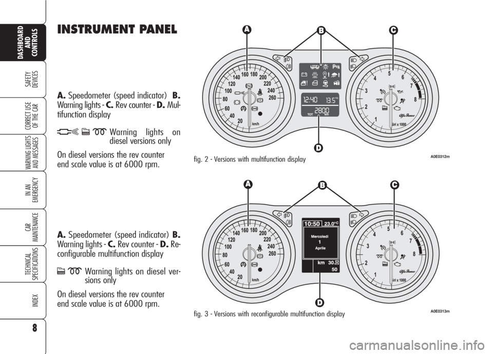
INSTRUMENT PANEL
A.Speedometer (speed indicator)B.
Warning lights - C.Rev counter - D.Mul-
tifunction display
hcmWarning lights on
diesel versions only
On diesel versions the rev counter
end scale value is at 6000 rpm.
A.Speedometer (speed indicator) B.
Warning lights - C.Rev counter - D.Re-
configurable multifunction display
cmWarning lights on diesel ver-
sions only
On diesel versions the rev counter
end scale value is at 6000 rpm.
8
SAFETY
DEVICES
WARNING LIGHTS
AND MESSAGES
IN AN
EMERGENCY
CAR
MAINTENANCE
TECHNICAL
SPECIFICATIONS
INDEX
DASHBOARD
AND
CONTROLS
CORRECT USE
OF THE CAR
fig. 2 - Versions with multifunction displayA0E0312m
fig. 3 - Versions with reconfigurable multifunction displayA0E0313m
Page 20 of 303
HOW TO DEACTIVATE
THE ALARM
Press button ├ŗ. The system will react as
follows (with the exception of certain
markets):
ŌØÆtwo brief flashes of the direction in-
dicators;
ŌØÆtwo brief ŌĆ£beepsŌĆØ;
ŌØÆdoor unlocking.
The alarm can be deactivated by fitting
the electronic key into the ignition
switch.
IMPORTANTOn certain versions any
attempt to break in detected by the sys-
tem will be indicated by a warning mes-
sage on the instrument panel display
when fitting the electronic key into the
ignition switch.VOLUMETRIC PROTECTION/
ANTI-RAISING SENSORS
To make sure that the protection sensors
are working properly, check that win-
dows and sunroof (where provided) are
shut.
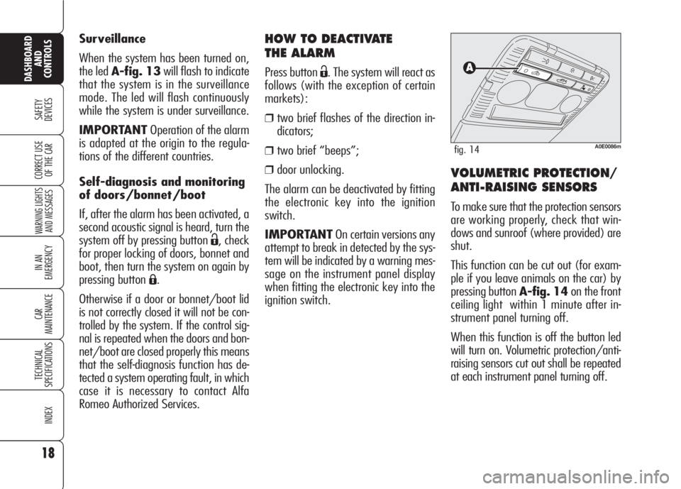
This function can be cut out (for exam-
ple if you leave animals on the car) by
pressing button A-fig. 14on the front
ceiling light within 1 minute after in-
strument panel turning off.
When this function is off the button led
will turn on. Volumetric protection/anti-
raising sensors cut out shall be repeated
at each instrument panel turning off. Surveillance
When the system has been turned on,
the led A-fig. 13will flash to indicate
that the system is in the surveillance
mode. The led will flash continuously
while the system is under surveillance.
IMPORTANTOperation of the alarm
is adapted at the origin to the regula-
tions of the different countries.
Self-diagnosis and monitoring
of doors/bonnet/boot
If, after the alarm has been activated, a
second acoustic signal is heard, turn the
system off by pressing button
├ŗ, check
for proper locking of doors, bonnet and
boot, then turn the system on again by
pressing button
Á.
Otherwise if a door or bonnet/boot lid
is not correctly closed it will not be con-
trolled by the system. If the control sig-
nal is repeated when the doors and bon-
net/boot are closed properly this means
that the self-diagnosis function has de-
tected a system operating fault, in which
case it is necessary to contact Alfa
Romeo Authorized Services.
18
SAFETY
DEVICES
WARNING LIGHTS
AND MESSAGES
IN AN
EMERGENCY
CAR
MAINTENANCE
TECHNICAL
SPECIFICATIONS
INDEX
DASHBOARD
AND
CONTROLS
CORRECT USE
OF THE CAR
A0E0086mfig. 14
Page 22 of 303
TURNING THE INSTRUMENT
PANEL OFF
With engine off and clutch and brake
pedals released, press button START/
STOPor remove the electronic key
from the ignition device.
A few seconds after the instrument pan-
el display will turn off gradually.
IMPORTANTContact Alfa Romeo Au-
thorized Services if the instrument pan-
el fails to turn off.
TURNING THE INSTRUMENT
PANEL ON
Proceed as follows:
ŌØÆfit the electronic key into the ignition
device;
ŌØÆif the electronic key is fitted yet, press
buttonSTART/STOPwithout
pressing the clutch or brake pedal.
To safeguard the battery, when leaving
the car with the instrument panel on,
electric and electronic devices will be de-
activated after approx. 1 hour.
IMPORTANTFit completely the elec-
tronic key into the ignition device until
it locks into place.
IMPORTANTContact Alfa Romeo Au-
thorized Services if the instrument pan-
el fails to turn on.
IMPORTANTIf when fitting the elec-
tronic key into the ignition device, the
warning light
Yon the instrument pan-
el comes on (on certain versions to-
gether with a message on the display),
check whether the electronic key is the
proper one and then try to refit it into
the ignition device. If the problem per-
sists contact Alfa Romeo Authorized Ser-
vices.
20
SAFETY
DEVICES
WARNING LIGHTS
AND MESSAGES
IN AN
EMERGENCY
CAR
MAINTENANCE
TECHNICAL
SPECIFICATIONS
INDEX
DASHBOARD
AND
CONTROLS
CORRECT USE
OF THE CAR
A0E0028mfig. 16
ENGINE STARTING
See paragraph ŌĆ£Engine startingŌĆØ in sec-
tion ŌĆ£Correct use of the carŌĆØ.
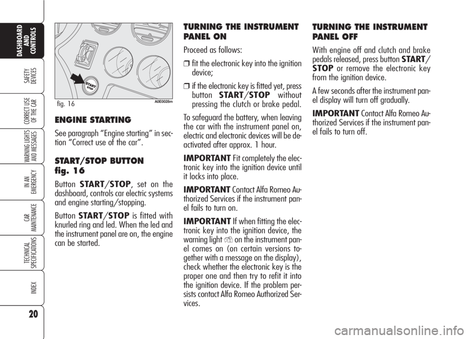
START/STOP BUTTON
fig. 16
ButtonSTART/STOP, set on the
dashboard, controls car electric systems
and engine starting/stopping.
ButtonSTART/STOPis fitted with
knurled ring and led. When the led and
the instrument panel are on, the engine
can be started.
Page 23 of 303
21
SAFETY
DEVICES
WARNING LIGHTS
AND MESSAGES
IN AN
EMERGENCY
CAR
MAINTENANCE
TECHNICAL
SPECIFICATIONS
INDEX
DASHBOARD
AND
CONTROLS
CORRECT USE
OF THE CAR
ed) (or as an alternative, on certain ver-
sions, a symbol and a message are dis-
played). In this event contact Alfa
Romeo Authorized Services.
IMPORTANTIf after trying to turn on
the instrument panel and/or to start the
engine, the instrument panel warning
light
>(where provided) (or as an al-
ternative, on certain versions the mes-
sage "Vehicle protection system not
available" is displayed), repeat the op-
eration moving the steering wheel in or-
der to release the steering lock. The dis-
played warning message will not impair
steering lock operation.
INSTRUMENTS
REV. COUNTER
Rev counter shows engine rpm. The red
zone at the scale bottom indicates that
the engine is running at excessive rpm
dangerous for mechanical components.
Do not drive with the pointer in this area.
IMPORTANTThe electronic injection
control system gradually shuts off the
flow of fuel when the engine is ŌĆ£over-
revvingŌĆØ (rev counter pointer in the red
area) resulting in a gradual loss of en-
gine power, in order to bring engine rpm
below to the safety limit.
The rev counter may, when the engine
is idling, indicate gradual or sudden in-
crease of engine revs as the case may
be; such behaviour is normal and must
not be interpreted as a faulty condition
as it occurs during normal operation, for
instance when climate control or electric
fan are switched on. In particular, slow
revs variation helps keep the battery
charged.
STEERING COLUMN LOCK
Engaging
The steering column lock will engage
5 seconds after removing the electron-
ic key from the ignition device and if the
following conditions are present:
ŌØÆengine off;
ŌØÆinstrument panel off with car at a
standstill;
ŌØÆelectronic key removed from ignition
device.
Disengaging
The steering column lock will disengage
after fitting the electronic key into the
ignition device.
IMPORTANTSwitching the engine off
when the car is running will not engage
the steering column lock till next switch-
ing off with car stopped. In this event
warning light
>(where provided) on the
instrument panel will come on (or as an
alternative, on certain versions, a sym-
bol and a message are displayed).
IMPORTANTSteering column lock
failure is indicated by the instrument
panel warning light
>(where provid-It is absolutely forbid-
den to carry out what-
ever after-market operation
involving steering system or
steering column modifications
(e.g.: installation of anti-theft
device) that could badly affect
performance and safety, cause
the lapse of warranty and al-
so result in non-compliance of
the car with homologation re-
quirements.
WARNING
Page 26 of 303
24
SAFETY
DEVICES
WARNING LIGHTS
AND MESSAGES
IN AN
EMERGENCY
CAR
MAINTENANCE
TECHNICAL
SPECIFICATIONS
INDEX
DASHBOARD
AND
CONTROLS
CORRECT USE
OF THE CAR
AUTOMATIC INSTRUMENT
PANEL LIGHT DIMMER
To give max. visibility and comfort un-
der whatever driving conditions (e.g.:
lights on in daylight, tunnels, etcŌĆ”),
the speedometer is fitted with a sensor
for adjusting automatically, after fitting
the electronic key into the ignition de-
vice and pressing button START/
STOP, the light intensity of the indi-
cations given on the instrument panel
display, sound system display (where
provided), climate control system dis-
play, radionavigation system display
(where provided), and instrument pan-
el gauges (fuel level gauge, engine oil
temperature gauge (petrol versions) or
supercharger pressure gauge (diesel ver-
sions) and engine coolant temperature
gauge).
MANUAL INSTRUMENT
PANEL LIGHT DIMMER
With this function it is possible to adjust
on 8 levels the light intensity of the indi-
cations given on the instrument panel dis-
play, sound system display (where pro-
vided), climate control system display, ra-
dionavigation system display (where pro-
vided), and instrument panel gauges (fu-
el level gauge, engine oil temperature
gauge (petrol versions) or supercharger
pressure gauge (diesel versions) and en-
gine coolant temperature gauge).
To increase light intensity press briefly
button+on the left-hand stalk, to re-
duce it press button ŌĆō: the display will
show an indication and a figure corre-
sponding to the current light intensity
level. This screen will be displayed for
a few seconds and then it will go off.
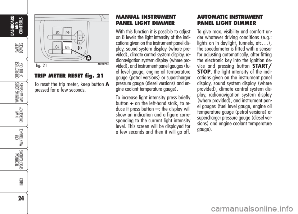
TRIP METER RESET fig. 21
To reset the trip meter, keep button A
pressed for a few seconds.
A0E0072mfig. 21
Page 27 of 303
25
SAFETY
DEVICES
WARNING LIGHTS
AND MESSAGES
IN AN
EMERGENCY
CAR
MAINTENANCE
TECHNICAL
SPECIFICATIONS
INDEX
DASHBOARD
AND
CONTROLS
CORRECT USE
OF THE CAR
INFORMATION ABOUT CAR
CONDITIONS (at event)
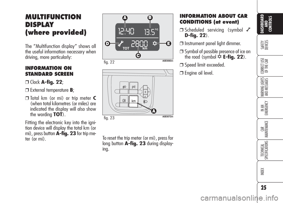
ŌØÆScheduled servicing (symbol ├Ą
D-fig. 22).
ŌØÆInstrument panel light dimmer.
ŌØÆSymbol of possible presence of ice on
the road (symbol
ŌłÜE-fig. 22).
ŌØÆSpeed limit exceeded.
ŌØÆEngine oil level.
MULTIFUNCTION
DISPLAY
(where provided)
The ŌĆ£Multifunction displayŌĆØ shows all
the useful information necessary when
driving, more particularly:
INFORMATION ON
STANDARD SCREEN
ŌØÆClockA-fig. 22;
ŌØÆExternal temperature B;
ŌØÆTotal km (or mi) or trip meter C
(when total kilometres (or miles) are
indicated the display will also show
the wording TOT).
Fitting the electronic key into the igni-
tion device will display the total km (or
mi), press button A-fig. 23for trip me-
ter (or mi).
A0E0060mfig. 22
A0E0072mfig. 23
To reset the trip meter (or mi), press for
long button A-fig. 23during display-
ing.
Page 32 of 303
30
SAFETY
DEVICES
WARNING LIGHTS
AND MESSAGES
IN AN
EMERGENCY
CAR
MAINTENANCE
TECHNICAL
SPECIFICATIONS
INDEX
DASHBOARD
AND
CONTROLS
CORRECT USE
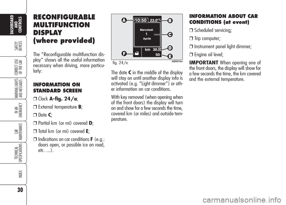
OF THE CARThe date Cin the middle of the display
will stay on until another display info is
activated (e.g. ŌĆ£Light dimmerŌĆØ) or oth-
er information on car conditions.
With key removed (when opening when
of the front doors) the display will turn
on and show for a few seconds the time,
covered km (or miles) and outside tem-
perature.
INFORMATION ABOUT CAR
CONDITIONS (at event)
ŌØÆScheduled servicing;
ŌØÆTrip computer;
ŌØÆInstrument panel light dimmer;
ŌØÆEngine oil level;
IMPORTANTWhen opening one of
the front doors, the display will show for
a few seconds the time, the km covered
and the external temperature.
RECONFIGURABLE
MULTIFUNCTION
DISPLAY
(where provided)
The ŌĆ£Reconfigurable multifunction dis-
playŌĆØ shows all the useful information
necessary when driving, more particu-
larly:
INFORMATION ON
STANDARD SCREEN
ŌØÆClockA-fig. 24/a;
ŌØÆExternal temperature B;
ŌØÆDateC;
ŌØÆPartial km (or mi) covered D;
ŌØÆTotal km (or mi) covered E;
ŌØÆIndications on car conditions F(e.g.:
doors open, or possible ice on road,
etc. ...).
A0E0015mfig. 24/a
Page 42 of 303
Reactivating the S.B.R.
(Seat Belt Reminder) buzzer
(Beep Seatb.) (where provided)
This function is displayed only after the
system has been deactivated by Alfa
Romeo Authorized Services.
Exit Menu (Quit setup)
Selecting this option will bring back to
standard screen.
ILLUMINATION OF REV
COUNTER/INSTRUMENTS
(NIGHT PANEL)
This function enables to turn on/off
(ON/OFF) the lights of the rev counter
and instruments. This function can be ac-
tivated (only with electronic key fitted in-
to ignition device, external lights on, and
speedometer built-in sensor in poor out-
side light setting), by pressing for long but-
tonŌĆō. When this function is on, the dis-
play will show a warning message. Once
on, the NIGHT PANELfunction can be
deactivated as follows:
ŌØÆby long press on button +(also with
external lights off);
ŌØÆremoving the electronic key from the
ignition device.
When function is off the display will show
a warning message.
Messages stay on the display for a few
seconds, then they will go off. To stop
displaying before time, briefly press but-
tonMENU. Scheduled Servicing (Service)
Through this function it is possible to dis-
play information connected to proper car
servicing.
Proceed as follows:
ŌØÆbriefly press button MENU: service
in km or mi, according to previous
setting, will be displayed (see para-
graph ŌĆ£UnitsŌĆØ);
ŌØÆbriefly press buttonMENUto go
back to the menu screen or press the
button for long to go back to the stan-
dard screen.
IMPORTANTThe Service schedule in-
cludes car maintenance every 30,000 km
(or 18,000 mi); this is shown automat-
ically, with the electronic key into the ig-
nition device starting from 2,000 km (or
1,240 mi) from this deadline and it will
be displayed in km or miles according to
the unit set. When a scheduled service in-
terval (ŌĆ£couponŌĆØ) is near to come, fitting
the electronic key into the ignition device
will display a message followed by the
number of km/mi to go before car ser-
vicing. Contact Alfa Romeo Authorized Ser-
vices to carry out any service operation
provided by the Service schedule or by the
Annual inspection plan, and to reset the
display.
40
SAFETY
DEVICES
WARNING LIGHTS
AND MESSAGES
IN AN
EMERGENCY
CAR
MAINTENANCE
TECHNICAL
SPECIFICATIONS
INDEX
DASHBOARD
AND
CONTROLS
CORRECT USE
OF THE CAR
Page 72 of 303
70
SAFETY
DEVICES
WARNING
LIGHTS AND
MESSAGES
IN AN
EMERGENCY
CAR
MAINTENANCE
TECHNICAL
SPECIFICATIONS
INDEX
CORRECT USE
OF THE CAR
DASHBOARD
AND
CONTROLS
EXTERNAL LIGHTS
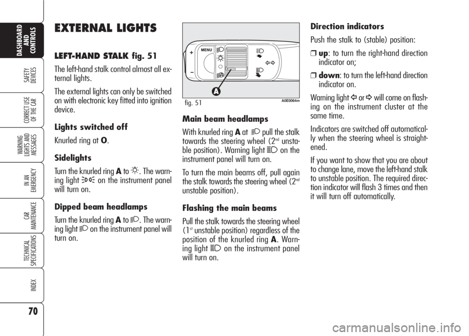
LEFT-HAND STALK fig. 51
The left-hand stalk control almost all ex-
ternal lights.
The external lights can only be switched
on with electronic key fitted into ignition
device.
Lights switched off
Knurled ring at O.
Sidelights
Turn the knurled ring Ato
6. The warn-
ing light
3on the instrument panel
will turn on.
Dipped beam headlamps
Turn the knurled ring Ato
2. The warn-
ing light
2on the instrument panel will
turn on.Main beam headlamps
With knurled ring Aat
2pull the stalk
towards the steering wheel (2ndunsta-
ble position). Warning light
1on the
instrument panel will turn on.
To turn the main beams off, pull again
the stalk towards the steering wheel (2
nd
unstable position).
Flashing the main beams
Pull the stalk towards the steering wheel
(1
stunstable position) regardless of the
position of the knurled ring A. Warn-
ing light
1on the instrument panel
will turn on. Direction indicators
Push the stalk to (stable) position:
ŌØÆup: to turn the right-hand direction
indicator on;
ŌØÆdown: to turn the left-hand direction
indicator on.
Warning light
├Äor┬źwill come on flash-
ing on the instrument cluster at the
same time.
Indicators are switched off automatical-
ly when the steering wheel is straight-
ened.
If you want to show that you are about
to change lane, move the left-hand stalk
to unstable position. The required direc-
tion indicator will flash 3 times and then
it will turn off automatically.A0E0064mfig. 51