Alfa Romeo 8C 2010 Owner handbook (in English)
8C 2010
Alfa Romeo
Alfa Romeo
https://www.carmanualsonline.info/img/27/31829/w960_31829-0.png
Alfa Romeo 8C 2010 Owner handbook (in English)
Trending: low beam, heating, fuel type, steering wheel adjustment, warning light, airbag off, battery
Page 161 of 223
159
6
IN AN EMERGENCY
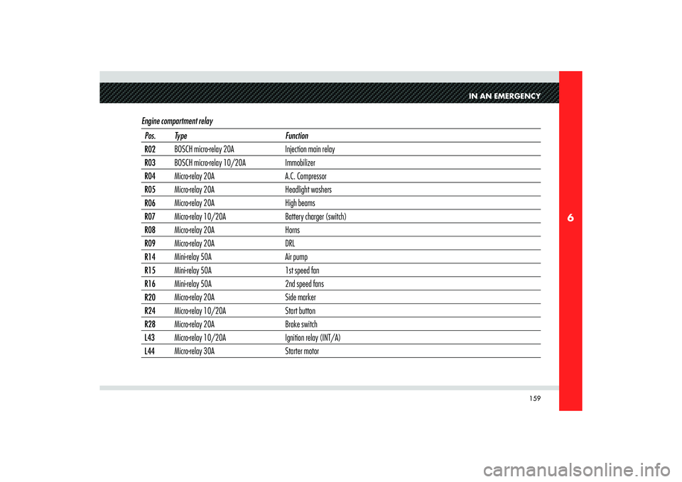
Engine compartment relay Pos. Type Function
R02BOSCH micro-relay 20A Injection main relay
R03BOSCH micro-relay 10/20A Immobilizer
R04Micro-relay 20A A.C. Compressor
R05Micro-relay 20A Headlight washers
R06Micro-relay 20A High beams
R07Micro-relay 10/20A Battery charger (switch)
R08Micro-relay 20A Horns
R09Micro-relay 20A DRL
R14Mini-relay 50A Air pump
R15Mini-relay 50A 1st speed fan
R16Mini-relay 50A 2nd speed fans
R20Micro-relay 20A Side marker
R24Micro-relay 10/20A Start button
R28Micro-relay 20A Brake switch
L43Micro-relay 10/20A Ignition relay (INT/A)
L44Micro-relay 30A Starter motor
Page 162 of 223
160
6
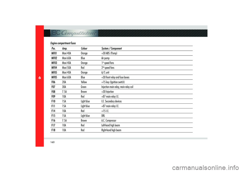
Engine compartment fuses Pos. Amp. Colour System / Component
MF01Maxi 40A Orange +30 ABS (Pump)
MF02Maxi 60A Blue Air pump
MF03Maxi 40A Orange 1
st speed fans
MF04Maxi 50A Red 2nd speed fans
MF05Maxi 40A Orange A/C unit
MF85Maxi 60A Blue +30 front relay and fuse boxes
F0620A Yellow +15 key (Ignition switch)
F0730A Green Injection main relay, main relay coil
F087.5A Brown +30 Injection
F0910A Red +87 main relay I.E.
F1015A Light blue I.E. Secondary devices
F1115A Light blue +87 main relay I.E.
F1410A Red +15 I.E.
F1515A Light blue DRL
F167.5A Brown A.C. Compressor
F1710A Red Left-hand high beam
F1810A Red Right-hand high beam
Page 163 of 223
161
6
IN AN EMERGENCY
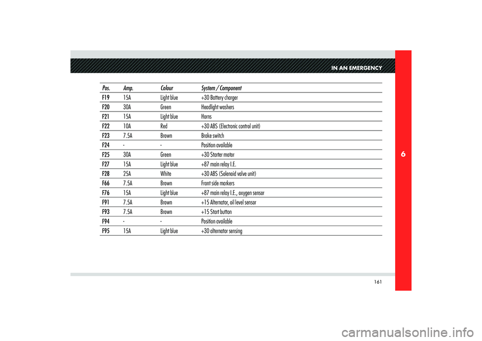
Pos. Amp. Colour System / Component
F1915A Light blue +30 Battery charger
F2030A Green Headlight washers
F2115A Light blue Horns
F2210A Red +30 ABS (Electronic control unit)
F237.5A Brown Brake switch
F24- - Position available
F2530A Green +30 Starter motor
F2715A Light blue +87 main relay I.E.
F2825A White +30 ABS (Solenoid valve unit)
F667.5A Brown Front side markers
F7615A Light blue +87 main relay I.E., oxygen sensor
F917.5A Brown +15 Alternator, oil level sensor
F937.5A Brown +15 Start button
F94- - Position available
F9515A Light blue +30 alternator sensing
Page 164 of 223
162
6
C
F-36
F-39
F-38
F-53
F-31F-52
F-41
F-43
F-40
F-44F-45
F-47
F-32
F-50
F-51F-46
F-33
F-37
F-42
F-12F-34
F-48
F-49
F-35
F-13
T01T12
T11T13
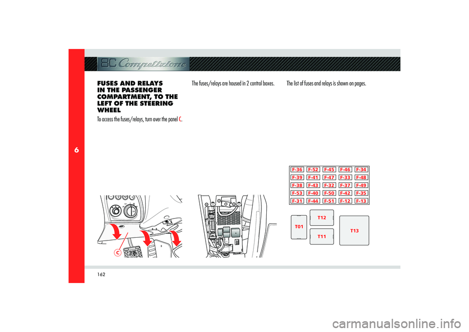
FUSES AND RELAYS
IN THE PASSENGER
COMPARTMENT, TO THE
LEFT OF THE STEERING
WHEEL
To access the fuses/relays, turn over the panel
C.The fuses/relays are housed in 2 control boxes. The list of fuses and relays is shown on pages.
Page 165 of 223
163
6
IN AN EMERGENCY
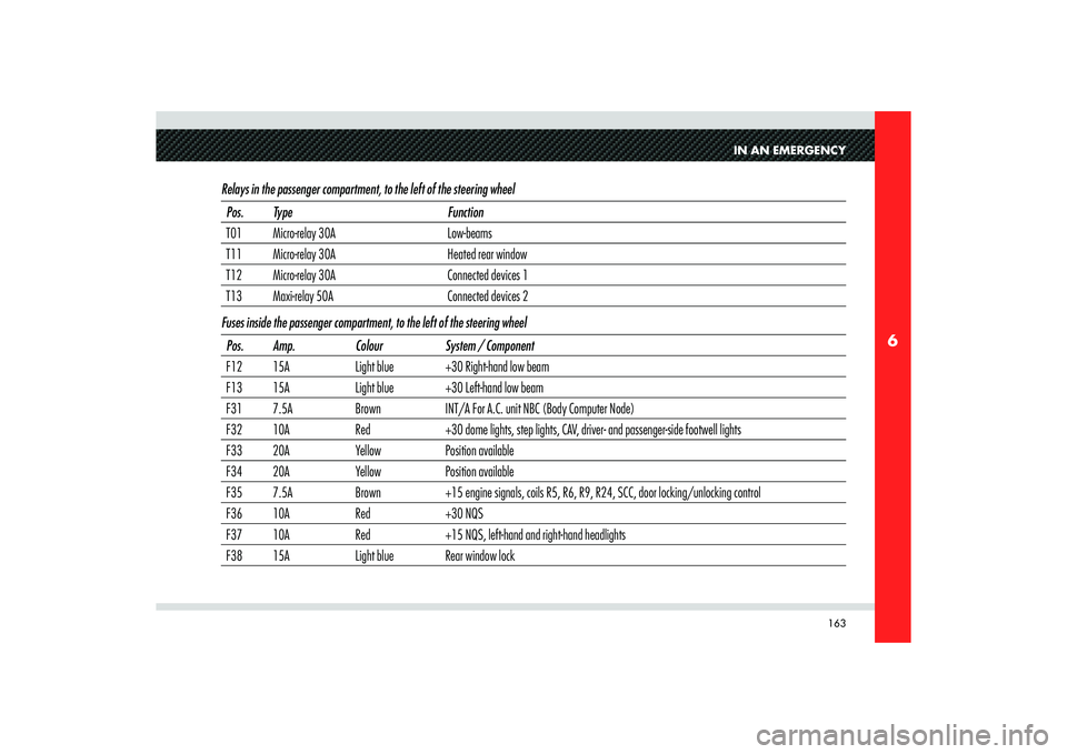
Relays in the passenger compartment, to the left of the steering wheelPos. Type Function
T01 Micro-relay 30A Low-beams
T11 Micro-relay 30A Heated rear window
T12 Micro-relay 30A Connected devices 1
T13 Maxi-relay 50A Connected devices 2
Fuses inside the passenger compartment, to the left of the steering wheel
Pos. Amp. Colour System / Component
F12 15A Light blue +30 Right-hand low beam
F13 15A Light blue +30 Left-hand low beam
F31 7.5A Brown INT/A For A.C. unit NBC (Body Computer Node)
F32 10A Red +30 dome lights, step lights, CAV, driver- and passenger-side footwell lights
F33 20A Yellow Position available
F34 20A Yellow Position available
F35 7.5A Brown +15 engine signals, coils R5, R6, R9, R24, SCC, door locking/unlocking control
F36 10A Red +30 NQS
F37 10A Red +15 NQS, left-hand and right-hand headlights
F38 15A Light blue Rear window lock
Page 166 of 223
164
6
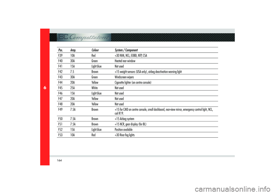
Pos. Amp. Colour System / Component
F39 10A Red +30 NIM, NCL, EOBD, NTP, CSA
F40 30A Green Heated rear window
F41 15A Light blue Not used
F42 7.5 Brown +15 weight sensors (USA only), airbag deactivation warning light
F43 30A Green Windscreen wipers
F44 20A Yellow Cigarette lighter (on centre console)
F45 25A White Not used
F46 15A Light blue Not used
F47 20A Yellow Not used
F48 20A Yellow Not used
F49 7.5A Brown +15 for CMD on centre console, small dashboard, rear-view mirror, emergency control light, NCL,
coil R19.
F50 7.5A Brown +15 Airbag system
F51 7.5A Brown +15 NCR, gear display (for BL)
F52 15A Light blue Position available
F53 10A Red +30 Rear fog lights
Page 167 of 223
165
6
D
IN AN EMERGENCY
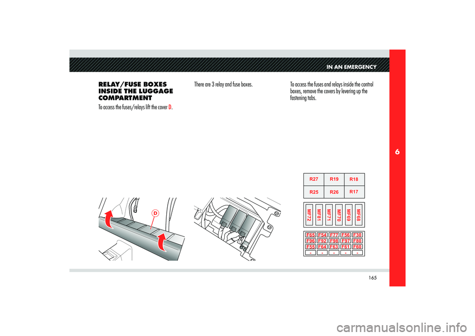
RELAY/FUSE BOXES
INSIDE THE LUGGAGE
COMPARTMENT
To access the fuses/relays lift the cover
D.There are 3 relay and fuse boxes. To access the fuses and relays inside the control
boxes, remove the covers by levering up the
fastening tabs.
Page 168 of 223
166
6
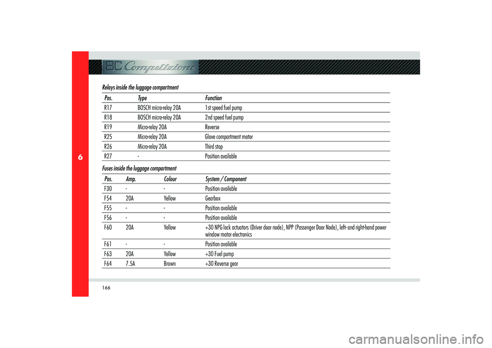
Relays inside the luggage compartmentPos. Type Function
R17 BOSCH micro-relay 20A 1st speed fuel pump
R18 BOSCH micro-relay 20A 2nd speed fuel pump
R19 Micro-relay 20A Reverse
R25 Micro-relay 20A Glove compartment motor
R26 Micro-relay 20A Third stop
R27 - Position available
Fuses inside the luggage compartment
Pos. Amp. Colour System / Component
F30 - - Position available
F54 20A Yellow Gearbox
F55 - - Position available
F56 - - Position available
F60 20A Yellow +30 NPG lock actuators (Driver door node), NPP (Passenger Door Node), left- and right-hand power
window motor electronics
F61 - - Position available
F63 20A Yellow +30 Fuel pump
F64 7.5A Brown +30 Reverse gear
Page 169 of 223
167
6
IN AN EMERGENCY
Pos. Amp. Colour System / Component
F65 7.5 Brown +30 Third stop
F77 10A Red Glove compartment motor
F80 25A White +30 Hi-Fi system (bass-box and subwoofer)
F92 - - Position available
F96 - - Position available
F97 20A Yellow NPG Power Supply (Driver’s door node)
F98 20A Yellow NPP Power Supply (Passenger Door Node)
MF68 Maxi 20A Yellow +30 Hi-Fi system amplifier
MF69 Maxi 40A Orange +30 EPB
MF70 Maxi 30A Green Q-Select gearbox pump
MF71 Maxi 50A Red Rear devices, Q-Select gearbox, glove compartment motor, Third stop
MF72 Maxi 50A Red NPG, NPP, door locks, reverse gear, fuel pumps
MF81 Maxi 50A Red Rear devices 4 (Hi-fi, power socket, NPG, NPP)
Page 170 of 223

168
6
B
C
A
IF THE BATTERY IS
FLAT First of all, we recommend that you read
the precautions contained in the section
”Maintenance“ to prevent the battery from
running flat and to help ensure its long life.
STARTING WITH THE
AUXILIARY BATTERY
See the chapter ”Starting the engine“ on page
114 in the section ”Using the vehicle”.WARNING: Under no circumstance should a
battery be used for an emergency start-up: This
could damage the electronic systems, particularly
the control units managing the ignition and fuel
supply functions.
RECHARGING THE
BATTERY
You are advised to recharge the battery slowly
and at a low amperage for about 24 hours.
Proceed as follows:
1) Deactivate the electronic alarm using the
radio control.
2) Lift the rear shelf
A and the box cover
B
and release the hooks
C.
WARNING: First disconnect the negative pole
terminal (–) then the positive pole one (+).3) Connect the battery charger cables to the
battery poles.WARNING: The battery is housed in a metal box, therefore, be extremely careful not to let the
battery charger clips come into contact with it.
4) Turn on the battery charger.
5) When the battery is recharged, turn off the
battery charger before disconnecting it from
the battery.
6) Reconnect the terminals to the battery
poles, observing the polarity.WARNING: First reconnect the positive pole
terminal (+) and then the negative pole one
(–).
WARNING: Before reconnecting the battery
terminals, check that the key has been removed
from the ignition or at least that it is in the STOP
position.
Trending: ABS, climate control, brake light, steering wheel, display, oil temperature, wheel size
