display Alfa Romeo Brera/Spider 2006 Owner handbook (in English)
[x] Cancel search | Manufacturer: ALFA ROMEO, Model Year: 2006, Model line: Brera/Spider, Model: Alfa Romeo Brera/Spider 2006Pages: 267, PDF Size: 7.21 MB
Page 39 of 267
37
SAFETY
DEVICES
WARNING
LIGHTS AND
MESSAGES
IN AN
EMERGENCY
CAR
MAINTENANCE
TECHNICAL
SPECIFICATIONS
INDEX
DASHBOARD
AND
CONTROLS
CORRECT USE
OF THE CAR
Reset TRIP B
End of partial mission
Start of new partial mission End of partial mission
Start of new
partial mission
Reset TRIP B
End of partial mission
Start of new
partial mission Reset GENERAL TRIP
End of complete mission
Start of new missionReset GENERAL TRIP
End of complete mission
Start of new mission
End of partial mission
Start of new
partial mission Reset TRIP B
Reset TRIP B TRIP B
TRIP B
TRIP B GENERAL TRIP
˙
˙
˙
˙˙
˙
˙ ˙
fig. 23
TRIP COMPUTER
General features
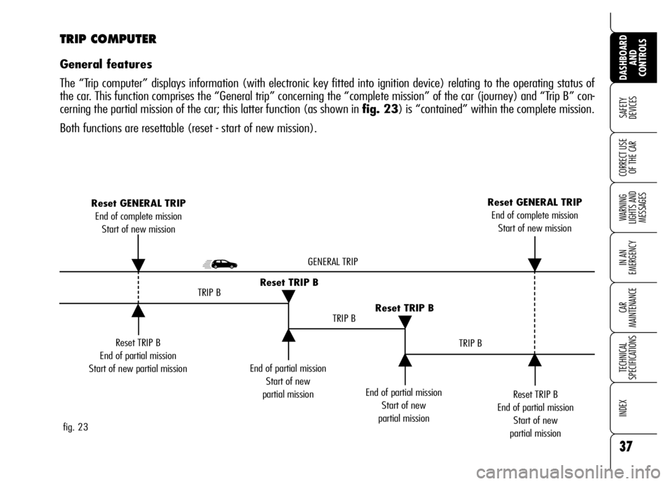
The “Trip computer” displays information (with electronic key fitted into ignition device) relating to the operating status of
the car. This function comprises the “General trip” concerning the “complete mission” of the car (journey) and “Trip B” con-
cerning the partial mission of the car; this latter function (as shown in fig. 23) is “contained” within the complete mission.
Both functions are resettable (reset - start of new mission).
Page 40 of 267
38
SAFETY
DEVICES
WARNING
LIGHTS AND
MESSAGES
IN AN
EMERGENCY
CAR
MAINTENANCE
TECHNICAL
SPECIFICATIONS
INDEX
DASHBOARD
AND
CONTROLS
CORRECT USE
OF THE CAR
Values displayed
Average consumption
This value shows the average con-
sumption from the start of the new mis-
sion.
Current consumption
This value shows instant fuel consump-
tion (this value is updated second by
second). If parking the car with engine
on, the display will show “- - - -”.
Average speed
This value shows the car average speed
as a function of the overall time elapsed
since the start of the new mission.
Travel time
This value shows the time elapsed since
the start of the new mission (driving
time).Range
This value shows the distance in km (or
mi) that the car can still cover before
needing fuel, assuming that driving con-
ditions are kept unvaried.
The display will show “- - - -“ in the fol-
lowing cases:
❒value lower than 50 km (or 30 mi);
❒car left parked with engine running
for over 5 minutes.
Travel Distance
This value shows the distance covered
from the start of the new mission.
Each time the battery is connected and
each time a new mission is started (re-
set), the display will show “0.0”.
IMPORTANTLacking information,
Trip computer values are displayed with
“- - - -”. When normal operating condi-
tion is reset, calculation of different units
will restart regularly. Values displayed
before the failure will not be reset. The “General Trip” displays the figures
relating to:
❒Average consumption
❒Current consumption
❒Average speed
❒Travel time
❒Range
❒Travel Distance
“Trip B” displays information concern-
ing :
❒Travel Distance B
❒Average consumption B
❒Average speed B
❒Travel time B.
Page 41 of 267
39
SAFETY
DEVICES
WARNING
LIGHTS AND
MESSAGES
IN AN
EMERGENCY
CAR
MAINTENANCE
TECHNICAL
SPECIFICATIONS
INDEX
DASHBOARD
AND
CONTROLS
CORRECT USE
OF THE CARTRIP BUTTON
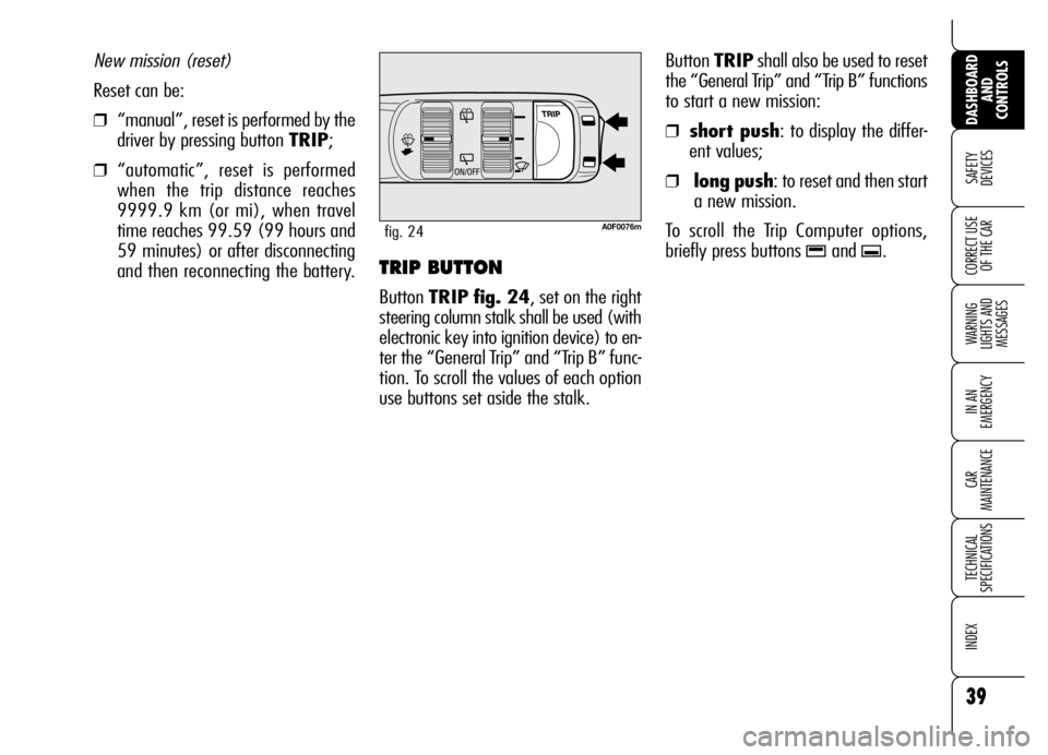
Button TRIP fig. 24, set on the right
steering column stalk shall be used (with
electronic key into ignition device) to en-
ter the “General Trip” and “Trip B” func-
tion. To scroll the values of each option
use buttons set aside the stalk.Button TRIPshall also be used to reset
the “General Trip” and “Trip B” functions
to start a new mission:
❒ short push: to display the differ-
ent values;
❒ long push: to reset and then start
a new mission.
To scroll the Trip Computer options,
briefly press buttons
-and .. New mission (reset)
Reset can be:
❒“manual”, reset is performed by the
driver by pressing button TRIP;
❒“automatic”, reset is performed
when the trip distance reaches
9999.9 km (or mi), when travel
time reaches 99.59 (99 hours and
59 minutes) or after disconnecting
and then reconnecting the battery.
A0F0076mfig. 24
Page 42 of 267
40
SAFETY
DEVICES
WARNING
LIGHTS AND
MESSAGES
IN AN
EMERGENCY
CAR
MAINTENANCE
TECHNICAL
SPECIFICATIONS
INDEX
DASHBOARD
AND
CONTROLS
CORRECT USE
OF THE CARIMPORTANT“General Trip” reset will
also reset the “Trip B” function, where-
as “Trip B” reset will only reset the in-
formation associated with this function.
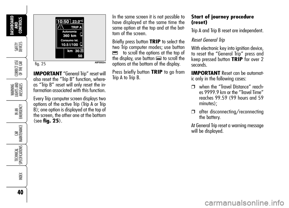
Every Trip computer screen displays two
options of the active Trip (Trip A or Trip
B); one option is displayed at the top of
the screen, the other one at the bottom
(see fig. 25).In the same screen it is not possible to
have displayed at the same time the
same option at the top and at the bot-
tom of the screen.
Briefly press button TRIPto select the
two Trip computer modes; use button
-to scroll the options at the top of
the display, use button
.to scroll the
options at the bottom of the display.
Press briefly button TRIPto go from
Trip A to Trip B.Start of journey procedure
(reset)
Trip A and Trip B reset are independent.
Reset General Trip
With electronic key into ignition device,
to reset the “General Trip” press and
keep pressed button TRIP for over 2
seconds.
IMPORTANTReset can be automat-
ic only in the following cases:
❒when the “Travel Distance” reach-
es 9999.9 km or the “Travel Time”
reaches 99.59 (99 hours and 59
minutes);
❒after disconnecting/reconnecting
the battery.
At General Trip reset a warning message
will be displayed.
A0F0052mfig. 25
Page 57 of 267

55
SAFETY
DEVICES
WARNING
LIGHTS AND
MESSAGES
IN AN
EMERGENCY
CAR
MAINTENANCE
TECHNICAL
SPECIFICATIONS
INDEX
DASHBOARD
AND
CONTROLS
CORRECT USE
OF THE CAR
I - Button for activating the MONO function (alignment of set temperatures), cor-
responding to driver’s one;
L- air recirculation on/off button;
M- climate control compressor on/off button;
N- passenger’s compartment temperature sensor Controls fig. 43
A- air distribution buttons (on driver and
passenger side);
B- knob for adjusting temperature on
the left side;
C - automatic operation button (FULL
AUTO);
D- climate control data display;
E - knob for adjusting temperature on
the right side;
F - rear window/door mirrors heating
on/off button;
G- MAX-DEF function button (fast de-
frosting/demisting function for wind-
screen, heated rear window and door
mirrors);
H - buttons for adjusting the fan speed
and for turning the climate control sys-
tem off (OFF);
fig. 43A0F0058m
Page 58 of 267
56
SAFETY
DEVICES
WARNING
LIGHTS AND
MESSAGES
IN AN
EMERGENCY
CAR
MAINTENANCE
TECHNICAL
SPECIFICATIONS
INDEX
DASHBOARD
AND
CONTROLS
CORRECT USE
OF THE CAR
AIR TEMPERATURE
ADJUSTMENT KNOBS
Turning the knob knurled rings (B/E),
clockwise or counter-clockwise, respec-
tively highers or lowers the temperature
of the air required respectively in the left
zone (knob B) or right zone (knob E)
of the passenger compartment. The tem-
peratures set are shown on the display
D.
Turning the knob knurled rings fully
clockwise or counter-clockwise until they
reach the extreme selections HI or LO,
the maximum heating or cooling func-
tions are respectively engaged.HI function (HIGH)
(maximum heating power)
It is switched on by setting a tempera-
ture of more than 32°C on the display,
and can be switched on independently
from the driver’s or passenger’s side,
or both of them; this setting brings the
system to the “one-zone” mode and it
is shown by both displays.
This functions can be switched on when
you wish to heat the passenger com-
partment as quickly as possible, by tak-
ing the greatest advantage from the sys-
tem potential.
The function uses the maximum tem-
perature of the heating fluid, whereas
air distribution and fan speed are con-
trolled automatically by the system.
SWITCHING THE CLIMATE
CONTROL SYSTEM ON
The system can be turned on by press-
ing any button (except
(, vand
MONO); it is however advisable to set
the required temperatures on the display
and then to press the AUTO button.
The climate control system allows to per-
sonalise required temperatures (driver and
passenger).
Page 59 of 267
57
SAFETY
DEVICES
WARNING
LIGHTS AND
MESSAGES
IN AN
EMERGENCY
CAR
MAINTENANCE
TECHNICAL
SPECIFICATIONS
INDEX
DASHBOARD
AND
CONTROLS
CORRECT USE
OF THE CAR
LO function (LOW)
(highest cooling power)
It is switched on by setting a tempera-
ture lower than 16°C on the display;
this setting is shown on the display. This
function can be switched on when you
wish to cool the passenger compartment
as quickly as possible, by taking the
greatest advantage from the system po-
tential.
The function cuts off air heating, switch-
es on both internal air recirculation (to
prevent hot air from entering the com-
partment) and the climate control com-
pressor, brings air distribution to
¯/˙
and the fan speed is controlled auto-
matically by the system. With the function switched on, howev-
er, all the manual settings can be made.
To switch the function off, you only need
to turn the ring of knob B/Eof the tem-
perature set to a value greater than
16°C; the opposite display will show
16°C.
Pressing button AUTO, the display will
show a temperature of 16°C and re-
turns to an operating condition with au-
tomatic temperature adjustment. This function should not be ac-
tivated when the engine is cold,
to prevent air not warm enough
from entering the passenger
compartment.
With the function switched on, howev-
er, all the manual settings can be made.
To switch the function off, you only need
to turn the ring of knob (Bor E) of the
temperature set to a value lower than
32°C; the opposite display will show
32°C.
Pressing button AUTO, the display will
show a temperature of 32°C and re-
turns to an operating condition with au-
tomatic temperature adjustment.
Page 60 of 267
58
SAFETY
DEVICES
WARNING
LIGHTS AND
MESSAGES
IN AN
EMERGENCY
CAR
MAINTENANCE
TECHNICAL
SPECIFICATIONS
INDEX
DASHBOARD
AND
CONTROLS
CORRECT USE
OF THE CAR
FAN SPEED ADJUSTMENT
Press buttons +/–to increase or to de-
crease the fan speed.
The fan speed is shown by the lit bars on
the display:
❒min fan speed = one bar lit;
❒max fan speed = 6 bars lit;
At starting, if climate control system is
operating in automatic mode, the fan
speed is kept at minimum until the en-
gine has started.
With compressor on and engine running,
the fan speed cannot fall below the min.
speed.
The fan can be cut off (all bars off) on-
ly if the climate control compressor has
been switched off by pressing button
√.
To restore automatic fan speed control
after a manual adjustment, press but-
tons AUTO. AUTO will also go off if the system (spe-
cially when compressor is turned off
manually) cannot reach or cannot keep
the required temperature.
Button
√will not turn off AUTO if the
system can keep the required comfort.
It is inadvisable to use
air recirculation on
rainy/cold days as it would
considerably increase the pos-
sibility of windows misting up
inside.
WARNING
AUTOMATIC OPERATION
(AUTO BUTTON)
Pressing button AUTO, the display will
show a temperature of 16°C and re-
turns to an operating condition with au-
tomatic temperature adjustment:
❒fan speed;
❒air distribution in passenger com-
partment;
❒air recirculation;
❒compressor;
and it will cancel all the previous man-
ual adjustments.
Wording FULL will disappear from the
display of the involved area (driver or
front passenger side) when performing
whatever operation (excluding temper-
ature change.
Page 62 of 267
60
SAFETY
DEVICES
WARNING
LIGHTS AND
MESSAGES
IN AN
EMERGENCY
CAR
MAINTENANCE
TECHNICAL
SPECIFICATIONS
INDEX
DASHBOARD
AND
CONTROLS
CORRECT USE
OF THE CAR
ALIGNING SET
TEMPERATURES
(MONO function)
Pressing button MONO automatically
aligns the temperature and air distribu-
tion on front and rear passenger area
with that on the driver area.
When this function is on, the circular led
around the button will turn on.
Turn knob Bto set the same tempera-
ture between the two zones.
Separate operation of the temperature
set by the passenger is restored auto-
matically by turning knob Eor by press-
ing again button MONO, the circular led
around the button will turn off.
CLIMATE CONTROL
COMPRESSOR ON/OFF
Press button √to turn the compressor
on: when climate control compressor is
on the circular led around the button will
turn on. Compressor will stay on also af-
ter turning the engine off.
To turn the compressor off press again
button
√.
With compressor off, the system will
check whether outside temperature is
higher or lower/same as the set one:
❒if outside temperature is lower than
the set one, the system will oper-
ate regularly also with compressor
off;
❒if outside temperature is higher than
the set one, the system will not be
able to keep the required condition,
the set temperature values will then
start to flash on the display.
HEATED REAR WINDOW
AND DOOR MIRROR
DEMISTING/DEFROSTING
Press button (to activate the demist-
ing/defrosting function: when this func-
tion is on, the circular led around the but-
ton will turn on.
On certain versions, turning this function
on will also activate windscreen de-
frosting in the windscreen wiper area.
This function is timed and switches off
automatically after few minutes, or by
pressing again the button or by turning
the engine off. It will not be switched
on automatically when restarting the en-
gine.
IMPORTANTDo not apply stickers on
the inside of the rear window over the
heating filaments to avoid damage that
might cause it to stop working properly.
Page 66 of 267
64
SAFETY
DEVICES
WARNING
LIGHTS AND
MESSAGES
IN AN
EMERGENCY
CAR
MAINTENANCE
TECHNICAL
SPECIFICATIONS
INDEX
DASHBOARD
AND
CONTROLS
CORRECT USE
OF THE CAR
SWITCHING THE CLIMATE
CONTROL SYSTEM OFF
Keep pressed button “–“ until the dis-
play shows OFF.
With climate control system off:
❒the system stores performed opera-
tions;
❒the display is off (OFF wording is dis-
played);
❒air recirculation is active (button led
on);
❒compressor is active;
❒ventilation is off.
To turn the climate control system on
again press button AUTO or any other
button (excluding
(, vand
MONO). Turning the climate control sys-
tem on again, air recirculation will be
again controlled automatically.
ADDITIONAL
HEATER (diesel
versions only)
(where provided)
The car is fitted with an additional heater
that supports the engine during cold or
winter weather to quickly reach a com-
fortable temperature in the passenger
compartment.
The additional heater works with the en-
gine running when the outside temper-
ature is below 20°C and the engine has
not yet reached normal operating tem-
perature.
After connecting/dis-
connecting the battery,
wait for 3 minutes at
least before fitting the elec-
tronic key into the ignition de-
vice in order to allow the cli-
mate control system control unit
to reset the positions of the
electric actuators that adjust air
temperature and distribution.