seats Alfa Romeo Brera/Spider 2006 Owner handbook (in English)
[x] Cancel search | Manufacturer: ALFA ROMEO, Model Year: 2006, Model line: Brera/Spider, Model: Alfa Romeo Brera/Spider 2006Pages: 267, PDF Size: 7.21 MB
Page 8 of 267
6
SAFETY
DEVICES
WARNING
LIGHTS AND
MESSAGES
IN AN
EMERGENCY
CAR
MAINTENANCE
TECHNICAL
SPECIFICATIONS
INDEX
DASHBOARD
AND
CONTROLS
CORRECT USE
OF THE CAR
D D D D
A A A A
S S S S
H H H H
B B B B
O O O O
A A A A
R R R R
D D D D
A A A A
N N N N
D D D D
C C C C
O O O O
N N N N
T T T T
R R R R
O O O O
L L L L
S S S S
WINDOW WASHING .......................................... 68
CRUISE CONTROL .............................................. 72
CEILING LIGHTS ................................................. 75
CONTROLS ........................................................ 77
INTERIOR FITTINGS............................................. 80
FIXED PANORAMA ROOF ..................................... 84
DOORS ............................................................ 86
POWER WINDOWS ............................................ 88
BOOT ............................................................... 91
BONNET............................................................ 96
ROOF RACK/SKI RACK ....................................... 98
HEADLIGHTS...................................................... 98
ABS SYSTEM .................................................... 100
VDC SYSTEM .................................................... 102
EOBD SYSTEM .................................................. 106
SOUND SYSTEM ................................................ 106
ACCESSORIES PURCHASED BY THE OWNER .......... 107
PARKING SENSORS ............................................ 108
AT THE FILLING STATION ..................................... 111
PROTECTING THE ENVIRONMENT ......................... 113 DASHBOARD...................................................... 7
INSTRUMENT PANEL .......................................... 8
SYMBOLS ........................................................ 9
THE ALFA ROMEO CODE SYSTEM.......................... 9
ELECTRONIC KEY ............................................... 11
ALARM ............................................................ 17
IGNITION DEVICE................................................ 19
INSTRUMENTS ................................................... 22
RECONFIGURABLE MULTIFUNCTION DISPLAY .......... 26
SEATS .............................................................. 41
HEAD RESTRAINTS.............................................. 44
STEERING WHEEL .............................................. 45
REARVIEW MIRRORS .......................................... 46
CLIMATE CONTROL SYSTEM ................................ 49
MANUAL CLIMATE CONTROL SYSTEM ................... 51
AUTOMATIC TWO-ZONE CLIMATE CONTROL SYSTEM 54
ADDITIONAL HEATER .......................................... 64
EXTERNAL LIGHTS ............................................. 65
Page 43 of 267
Upholstery of your car
has been designed to
withstand wear deriv-
ing from common use of the car.
You are however recommended
to avoid strong and/or contin-
uous scratching with clothing ac-
cessories such as metallic buck-
les, studs, Velcro fastenings and
the like, since these items cause
circumscribed stress of the cov-
er fabric that could lead to yarn
breaking, and damage the cov-
er as a consequence.
41
SAFETY
DEVICES
WARNING
LIGHTS AND
MESSAGES
IN AN
EMERGENCY
CAR
MAINTENANCE
TECHNICAL
SPECIFICATIONS
INDEX
DASHBOARD
AND
CONTROLS
CORRECT USE
OF THE CAR
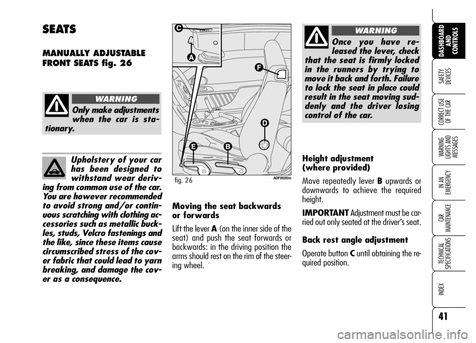
Height adjustment
(where provided)
Move repeatedly lever Bupwards or
downwards to achieve the required
height.
IMPORTANTAdjustment must be car-
ried out only seated at the driver’s seat.
Back rest angle adjustment
Operate button Cuntil obtaining the re-
quired position.
SEATS
MANUALLY ADJUSTABLE
FRONT SEATS fig. 26
Only make adjustments
when the car is sta-
tionary.
WARNING
A0F0020mfig. 26
Once you have re-
leased the lever, check
that the seat is firmly locked
in the runners by trying to
move it back and forth. Failure
to lock the seat in place could
result in the seat moving sud-
denly and the driver losing
control of the car.
WARNING
Moving the seat backwards
or forwards
Lift the lever A(on the inner side of the
seat) and push the seat forwards or
backwards: in the driving position the
arms should rest on the rim of the steer-
ing wheel.
Page 44 of 267
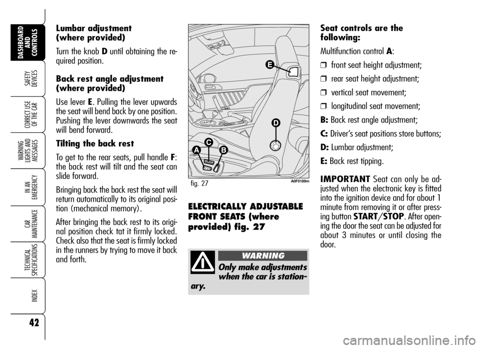
Lumbar adjustment
(where provided)
Turn the knob Duntil obtaining the re-
quired position.
Back rest angle adjustment
(where provided)
Use lever E. Pulling the lever upwards
the seat will bend back by one position.
Pushing the lever downwards the seat
will bend forward.
Tilting the back rest
To get to the rear seats, pull handle F:
the back rest will tilt and the seat can
slide forward.
Bringing back the back rest the seat will
return automatically to its original posi-
tion (mechanical memory).
After bringing the back rest to its origi-
nal position check tat it firmly locked.
Check also that the seat is firmly locked
in the runners by trying to move it back
and forth.
42
SAFETY
DEVICES
WARNING
LIGHTS AND
MESSAGES
IN AN
EMERGENCY
CAR
MAINTENANCE
TECHNICAL
SPECIFICATIONS
INDEX
DASHBOARD
AND
CONTROLS
CORRECT USE
OF THE CAR
ELECTRICALLY ADJUSTABLE
FRONT SEATS (where
provided) fig. 27
Seat controls are the
following:
Multifunction control A:
❒front seat height adjustment;
❒rear seat height adjustment;
❒vertical seat movement;
❒longitudinal seat movement;
B:Back rest angle adjustment;
C:Driver’s seat positions store buttons;
D:Lumbar adjustment;
E:Back rest tipping.
IMPORTANTSeat can only be ad-
justed when the electronic key is fitted
into the ignition device and for about 1
minute from removing it or after press-
ing button START/STOP. After open-
ing the door the seat can be adjusted for
about 3 minutes or until closing the
door.
Only make adjustments
when the car is station-
ary.
WARNING
A0F0189mfig. 27
Page 45 of 267
43
SAFETY
DEVICES
WARNING
LIGHTS AND
MESSAGES
IN AN
EMERGENCY
CAR
MAINTENANCE
TECHNICAL
SPECIFICATIONS
INDEX
DASHBOARD
AND
CONTROLS
CORRECT USE
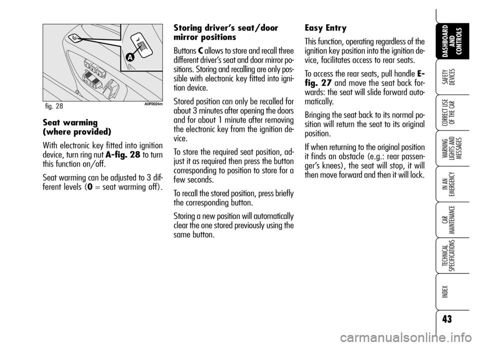
OF THE CARSeat warming
(where provided)
With electronic key fitted into ignition
device, turn ring nut A-fig. 28 to turn
this function on/off.
Seat warming can be adjusted to 3 dif-
ferent levels (0= seat warming off).
A0F0024mfig. 28
Easy Entry
This function, operating regardless of the
ignition key position into the ignition de-
vice, facilitates access to rear seats.
To access the rear seats, pull handle E-
fig. 27and move the seat back for-
wards: the seat will slide forward auto-
matically.
Bringing the seat back to its normal po-
sition will return the seat to its original
position.
If when returning to the original position
it finds an obstacle (e.g.: rear passen-
ger’s knees), the seat will stop, it will
then move forward and then it will lock. Storing driver’s seat/door
mirror positions
Buttons Callows to store and recall three
different driver’s seat and door mirror po-
sitions. Storing and recalling are only pos-
sible with electronic key fitted into igni-
tion device.
Stored position can only be recalled for
about 3 minutes after opening the doors
and for about 1 minute after removing
the electronic key from the ignition de-
vice.
To store the required seat position, ad-
just it as required then press the button
corresponding to position to store for a
few seconds.
To recall the stored position, press briefly
the corresponding button.
Storing a new position will automatically
clear the one stored previously using the
same button.
Page 46 of 267
44
SAFETY
DEVICES
WARNING
LIGHTS AND
MESSAGES
IN AN
EMERGENCY
CAR
MAINTENANCE
TECHNICAL
SPECIFICATIONS
INDEX
DASHBOARD
AND
CONTROLS
CORRECT USE
OF THE CARREAR HEAD RESTRAINTS
Rear seats are fitted with two head re-
straints.
If required, head restraints can be re-
moved as follows:
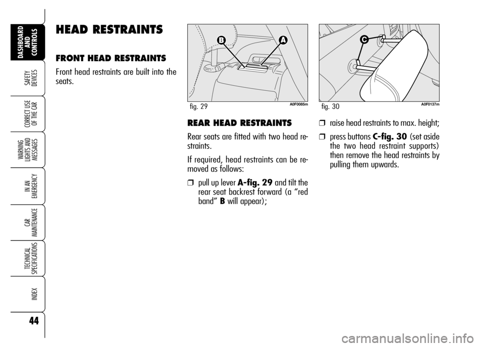
❒pull up lever A-fig. 29 and tilt the
rear seat backrest forward (a “red
band” Bwill appear);
HEAD RESTRAINTS
FRONT HEAD RESTRAINTS
Front head restraints are built into the
seats.
A0F0137mfig. 30
❒raise head restraints to max. height;
❒press buttons C-fig. 30 (set aside
the two head restraint supports)
then remove the head restraints by
pulling them upwards.
A0F0085mfig. 29
Page 49 of 267
47
SAFETY
DEVICES
WARNING
LIGHTS AND
MESSAGES
IN AN
EMERGENCY
CAR
MAINTENANCE
TECHNICAL
SPECIFICATIONS
INDEX
DASHBOARD
AND
CONTROLS
CORRECT USE
OF THE CARManual mirror folding
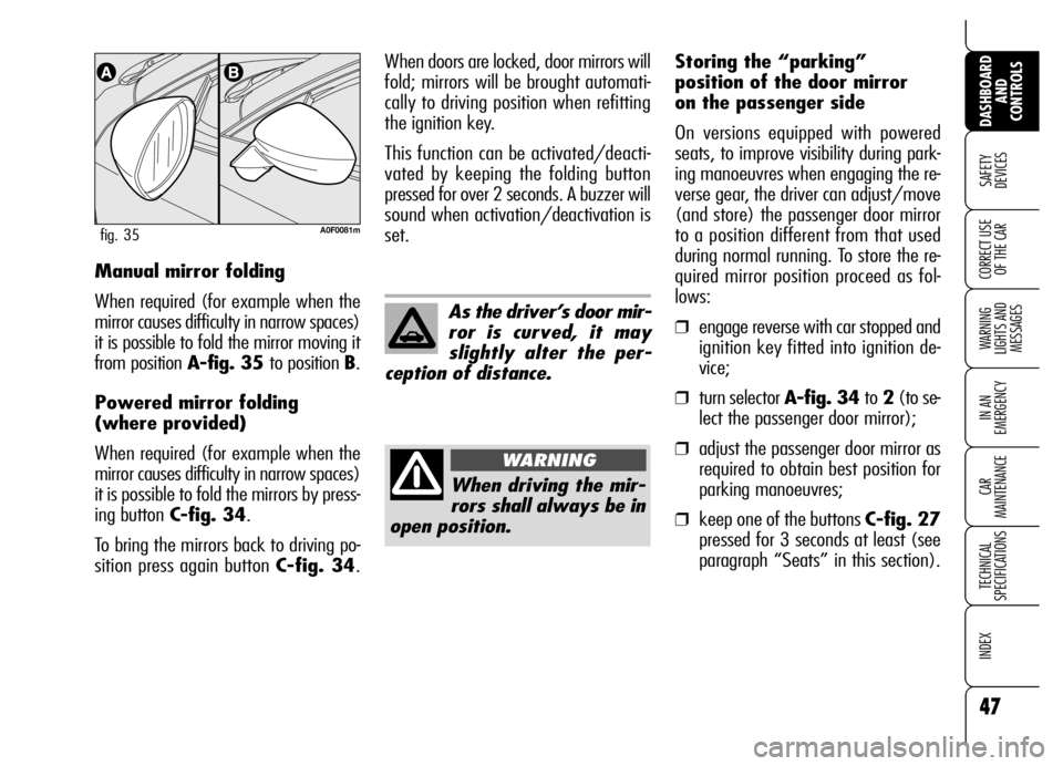
When required (for example when the
mirror causes difficulty in narrow spaces)
it is possible to fold the mirror moving it
from position A-fig. 35 to position B.
Powered mirror folding
(where provided)
When required (for example when the
mirror causes difficulty in narrow spaces)
it is possible to fold the mirrors by press-
ing button C-fig. 34.
To bring the mirrors back to driving po-
sition press again button C-fig. 34.
A0F0081mfig. 35
As the driver’s door mir-
ror is curved, it may
slightly alter the per-
ception of distance.
When driving the mir-
rors shall always be in
open position.
WARNING
When doors are locked, door mirrors will
fold; mirrors will be brought automati-
cally to driving position when refitting
the ignition key.
This function can be activated/deacti-
vated by keeping the folding button
pressed for over 2 seconds. A buzzer will
sound when activation/deactivation is
set.Storing the “parking”
position of the door mirror
on the passenger side
On versions equipped with powered
seats, to improve visibility during park-
ing manoeuvres when engaging the re-
verse gear, the driver can adjust/move
(and store) the passenger door mirror
to a position different from that used
during normal running. To store the re-
quired mirror position proceed as fol-
lows:
❒engage reverse with car stopped and
ignition key fitted into ignition de-
vice;
❒turn selector A-fig. 34 to2(to se-
lect the passenger door mirror);
❒adjust the passenger door mirror as
required to obtain best position for
parking manoeuvres;
❒keep one of the buttons C-fig. 27
pressed for 3 seconds at least (see
paragraph “Seats” in this section).
Page 51 of 267
49
SAFETY
DEVICES
WARNING
LIGHTS AND
MESSAGES
IN AN
EMERGENCY
CAR
MAINTENANCE
TECHNICAL
SPECIFICATIONS
INDEX
DASHBOARD
AND
CONTROLS
CORRECT USE
OF THE CAR
CLIMATE CONTROL SYSTEM
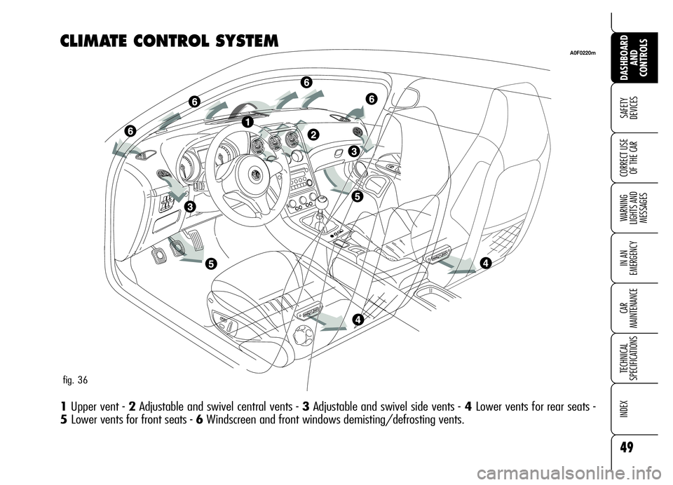
1Upper vent - 2Adjustable and swivel central vents - 3Adjustable and swivel side vents -4Lower vents for rear seats -
5 Lower vents for front seats - 6Windscreen and front windows demisting/defrosting vents.
A0F0220m
fig. 36
Page 82 of 267
80
SAFETY
DEVICES
WARNING
LIGHTS AND
MESSAGES
IN AN
EMERGENCY
CAR
MAINTENANCE
TECHNICAL
SPECIFICATIONS
INDEX
DASHBOARD
AND
CONTROLS
CORRECT USE
OF THE CAR
INTERIOR FITTINGS
CENTRAL ARMREST
The central armrest is located between
the front seats. Inside the armrest is
housed an air-conditioned food box
(where provided) (see next paragraph).
A0F0141mfig. 57
Pay attention not to
spill the drinks into the
food box.
A0F0039mfig. 56
Air-conditioned food box
(where provided)
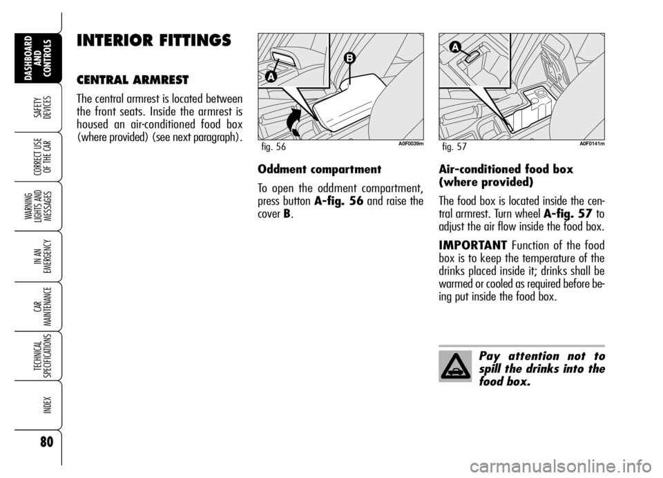
The food box is located inside the cen-
tral armrest. Turn wheel A-fig. 57 to
adjust the air flow inside the food box.
IMPORTANTFunction of the food
box is to keep the temperature of the
drinks placed inside it; drinks shall be
warmed or cooled as required before be-
ing put inside the food box. Oddment compartment
To open the oddment compartment,
press button A-fig. 56and raise the
cover B.
Page 85 of 267
83
SAFETY
DEVICES
WARNING
LIGHTS AND
MESSAGES
IN AN
EMERGENCY
CAR
MAINTENANCE
TECHNICAL
SPECIFICATIONS
INDEX
DASHBOARD
AND
CONTROLS
CORRECT USE
OF THE CAR
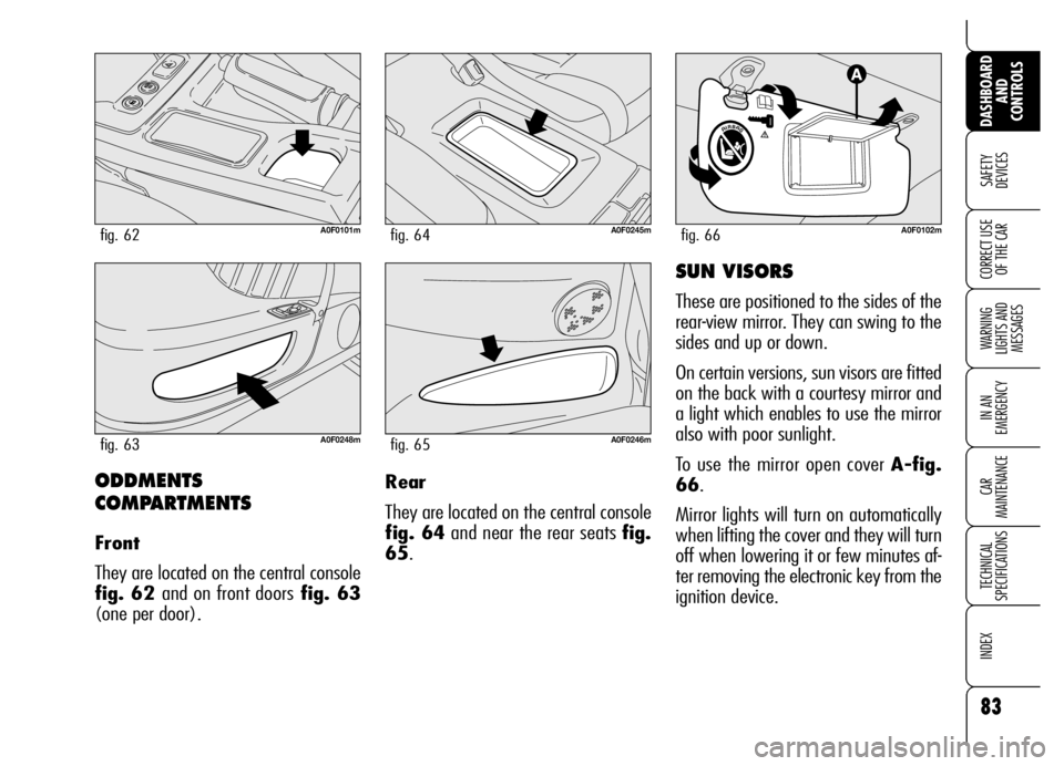
ODDMENTS
COMPARTMENTS
Front
They are located on the central console
fig. 62 and on front doorsfig. 63
(one per door).
A0F0101mfig. 62
A0F0248mfig. 63
A0F0245mfig. 64
A0F0246mfig. 65
A0F0102mfig. 66
SUN VISORS
These are positioned to the sides of the
rear-view mirror. They can swing to the
sides and up or down.
On certain versions, sun visors are fitted
on the back with a courtesy mirror and
a light which enables to use the mirror
also with poor sunlight.
To use the mirror open cover A-fig.
66.
Mirror lights will turn on automatically
when lifting the cover and they will turn
off when lowering it or few minutes af-
ter removing the electronic key from the
ignition device. Rear
They are located on the central console
fig. 64and near the rear seats fig.
65.
Page 94 of 267
92
SAFETY
DEVICES
WARNING
LIGHTS AND
MESSAGES
IN AN
EMERGENCY
CAR
MAINTENANCE
TECHNICAL
SPECIFICATIONS
INDEX
DASHBOARD
AND
CONTROLS
CORRECT USE
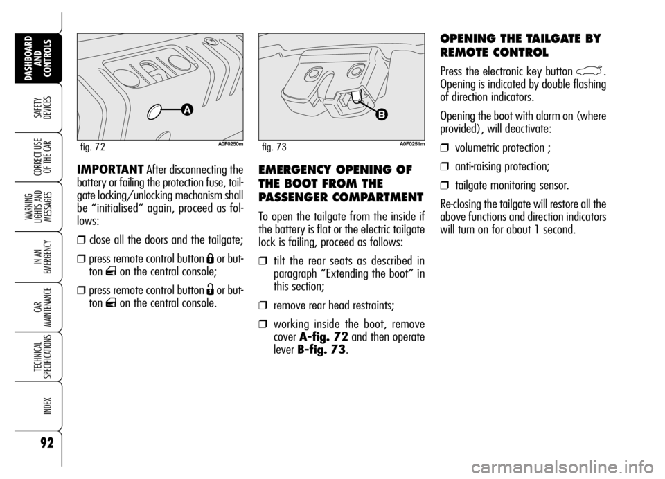
OF THE CAREMERGENCY OPENING OF
THE BOOT FROM THE
PASSENGER COMPARTMENT
To open the tailgate from the inside if
the battery is flat or the electric tailgate
lock is failing, proceed as follows:
❒tilt the rear seats as described in
paragraph “Extending the boot” in
this section;
❒remove rear head restraints;
❒working inside the boot, remove
cover A-fig. 72and then operate
lever B-fig. 73. IMPORTANTAfter disconnecting the
battery or failing the protection fuse, tail-
gate locking/unlocking mechanism shall
be “initialised” again, proceed as fol-
lows:
❒close all the doors and the tailgate;
❒press remote control button Áor but-
ton
qon the central console;
❒press remote control button Ëor but-
ton
qon the central console.
A0F0250mfig. 72
OPENING THE TAILGATE BY
REMOTE CONTROL
Press the electronic key button `.
Opening is indicated by double flashing
of direction indicators.
Opening the boot with alarm on (where
provided), will deactivate:
❒volumetric protection ;
❒anti-raising protection;
❒tailgate monitoring sensor.
Re-closing the tailgate will restore all the
above functions and direction indicators
will turn on for about 1 second.
A0F0251mfig. 73