clock Alfa Romeo Brera/Spider 2008 Owner handbook (in English)
[x] Cancel search | Manufacturer: ALFA ROMEO, Model Year: 2008, Model line: Brera/Spider, Model: Alfa Romeo Brera/Spider 2008Pages: 270, PDF Size: 3.93 MB
Page 17 of 270
16
SAFETY
DEVICES
WARNING
LIGHTS AND
MESSAGES
IN AN
EMERGENCY
CAR
MAINTENANCE
TECHNICAL
SPECIFICATIONS
INDEX
DASHBOARD
AND
CONTROLS
CORRECT USE
OF THE CAR
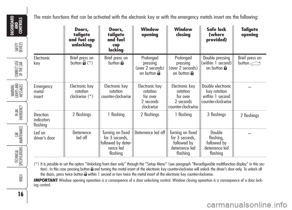
The main functions that can be activated with the electronic key or with the emergency metals insert are the following:
(*) It is possible to set the option “Unlocking front door only” through the “Setup Menu” (see paragraph “Reconfigurable multifunction display” in this sec-
tion). In this case pressing button
Áand turning the metal insert of the electronic key counter-clockwise will unlock the driver’s door only. To unlock all
the doors, press twice button
Ëwithin 1 second or turn twice the metal insert of the electronic key counter-clockwise.
IMPORTANTWindow opening operation is a consequence of a door unlocking control. Window closing operation is a consequence of a door lock-
ing control.
Electronic
key
Emergency
metal
insert
Direction
indicators
flashing
Led on
driver’s door
Doors,
tailgate
and fuel cap
unlocking
Brief press on
button
Ë(*)
Electronic key
rotation
clockwise (*)
2 flashings
Deterrence
led offDoors,
tailgate
and fuel
cap
locking
Brief press on
button
Á
Electronic key
rotation
counter-clockwise
1 flashing
Turning on fixed
for 3 seconds,
followed by deter-
rence led
flashingWindow
opening
Prolonged
pressing
(over 2 seconds)
on button
Ë
Electronic key
rotation
for over
2 seconds
clockwise
2 flashings
Deterrence led offWindow
closing
Prolonged
pressing
(over 2 seconds)
on button
Á
Electronic key
rotation
for over
2 seconds
counter-clockwise
1 flashing
Turning on fixed
for 3 seconds,
followed by
deterrence led
flashingSafe lock
(where
provided)
Double pressing
(within 1 second)
on button
Á
Double electronic
key rotation
within 1 second
counter-clockwise
3 flashings
Double
flashing,
followed by
deterrence led
flashingTailgate
opening
Brief press on
button
`
–
2 flashings
–
Page 27 of 270
26
SAFETY
DEVICES
WARNING
LIGHTS AND
MESSAGES
IN AN
EMERGENCY
CAR
MAINTENANCE
TECHNICAL
SPECIFICATIONS
INDEX
DASHBOARD
AND
CONTROLS
CORRECT USE
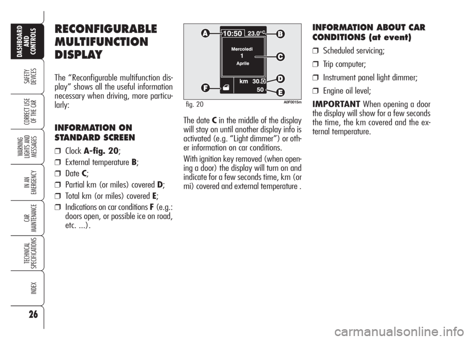
OF THE CARThe date Cin the middle of the display
will stay on until another display info is
activated (e.g. “Light dimmer”) or oth-
er information on car conditions.
With ignition key removed (when open-
ing a door) the display will turn on and
indicate for a few seconds time, km (or
mi) covered and external temperature .
INFORMATION ABOUT CAR
CONDITIONS (at event)
❒Scheduled servicing;
❒Trip computer;
❒Instrument panel light dimmer;
❒Engine oil level;
IMPORTANTWhen opening a door
the display will show for a few seconds
the time, the km covered and the ex-
ternal temperature.
RECONFIGURABLE
MULTIFUNCTION
DISPLAY
The “Reconfigurable multifunction dis-
play” shows all the useful information
necessary when driving, more particu-
larly:
INFORMATION ON
STANDARD SCREEN
❒ClockA-fig. 20;
❒External temperature B;
❒DateC;
❒Partial km (or miles) covered D;
❒Total km (or miles) covered E;
❒Indications on car conditions F(e.g.:
doors open, or possible ice on road,
etc. ...).
A0F0015mfig. 20
Page 29 of 270
28
SAFETY
DEVICES
WARNING
LIGHTS AND
MESSAGES
IN AN
EMERGENCY
CAR
MAINTENANCE
TECHNICAL
SPECIFICATIONS
INDEX
DASHBOARD
AND
CONTROLS
CORRECT USE
OF THE CAR
Selecting “Date” and “Clock”:
❒briefly press button MENUto select
the first value to change (e.g. hours
/minutes or year /month /day);
❒operate buttons +or–(by single
press) to select the new setting;
❒briefly press button MENUto store
new setting and go back to the pre-
viously selected option of the main
menu, if this is the last one you will
go back to the previously selected
option of the main menu.
ENGINE OIL
LEVEL INDICATION
Fitting the electronic key into the igni-
tion device, the display will show for a
few seconds the engine oil level. At this
stage, to clear this indication and to go
to next screen, press button MENU.
Low/excessive oil level will be indicat-
ed by a dedicated warning message on
the display.
IMPORTANT Check the proper en-
gine oil level on the dipstick (see para-
graph “Checking levels” in section “Car
maintenance”).
IMPORTANTProper engine oil level
shall be checked with the car on level
ground.
IMPORTANTFor proper oil level in-
dication, after fitting the key, wait for
about 2 seconds before starting the en-
gine.
IMPORTANTEngine oil level could in-
crease after a long stop. Selecting an option of the main
menu with submenu:❒briefly press button MENUto dis-
play the first submenu option;
❒operate buttons +or–(by single
press) to scroll all submenu options;
❒briefly press button MENUto select
the displayed submenu option and
to enter the corresponding setup
menu;
❒ operate buttons +or–(by single
press) to select the new setting of this
submenu option;
❒ briefly press button MENUto store
the new setting and go back to the
previously selected submenu option.
Page 30 of 270
29
SAFETY
DEVICES
WARNING
LIGHTS AND
MESSAGES
IN AN
EMERGENCY
CAR
MAINTENANCE
TECHNICAL
SPECIFICATIONS
INDEX
DASHBOARD
AND
CONTROLS
CORRECT USE
OF THE CAR
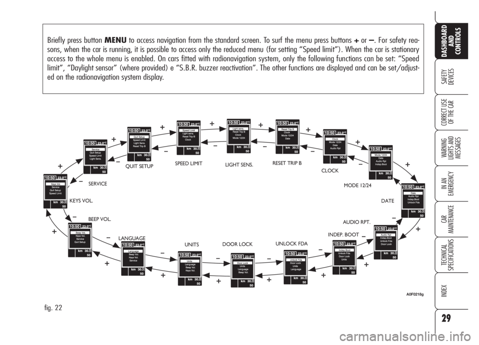
Briefly press button MENUto access navigation from the standard screen. To surf the menu press buttons +or–. For safety rea-
sons, when the car is running, it is possible to access only the reduced menu (for setting “Speed limit”). When the car is stationary
access to the whole menu is enabled. On cars fitted with radionavigation system, only the following functions can be set: “Speed
limit”, “Daylight sensor” (where provided) e “S.B.R. buzzer reactivation”. The other functions are displayed and can be set/adjust-
ed on the radionavigation system display.
fig. 22
BEEP VOL.SERVICEQUIT SETUPLIGHT SENS.RESET TRIP B
CLOCK
MODE 12/24
DATE
AUDIO RPT.
INDEP. BOOT
UNLOCK FDA
DOOR LOCK
UNITS KEYS VOL.
LANGUAGESPEED LIMIT
A0F0218g
Page 32 of 270
31
SAFETY
DEVICES
WARNING
LIGHTS AND
MESSAGES
IN AN
EMERGENCY
CAR
MAINTENANCE
TECHNICAL
SPECIFICATIONS
INDEX
DASHBOARD
AND
CONTROLS
CORRECT USE
OF THE CAR
IMPORTANT Every press (pulse) on
the button +/–increases/decreases by
one unit. Keeping button +/–pressed
obtains fast increase/decrease. When
you are near the required setting com-
plete adjustment with single presses.
❒briefly press button MENUto go
back to the menu screen or press the
button for long to go back to the
standard screen. Setting the clock (Clock)
This function enables to set the clock.
Proceed as follows:
❒briefly press button MENU: “hours”
will be displayed;
❒press button +or–for setting as re-
quired;
❒briefly press button MENU: “min-
utes” will be displayed;
❒press button +or–for setting as re-
quired;Clock mode (Mode 12/24)
This function is used to set the clock in
the 12h or 24h mode.
To adjust proceed as follows:
❒briefly press button MENU: the dis-
playwill show12h or 24h (accord-
ing to previous setting);
❒press button +or–for setting as re-
quired;
❒briefly press button MENUto go
back to the menu screen or press the
button for long to go back to the
standard screen.
Page 57 of 270
56
SAFETY
DEVICES
WARNING
LIGHTS AND
MESSAGES
IN AN
EMERGENCY
CAR
MAINTENANCE
TECHNICAL
SPECIFICATIONS
INDEX
DASHBOARD
AND
CONTROLS
CORRECT USE
OF THE CAR
AIR TEMPERATURE
ADJUSTMENT KNOBS
Turning the knob knurled rings (B/E),
clockwise or counter-clockwise, respec-
tively highers or lowers the temperature
of the air required respectively in the left
zone (knob B) or right zone (knob E)
of the passenger compartment. The tem-
peratures set are shown on the display
D.
Turning the knob knurled rings fully
clockwise or counter-clockwise until they
reach the extreme selections HIorLO,
the maximum heating or cooling func-
tions are respectively engaged.HI function (HIGH)
(maximum heating power)
It is switched on by setting a tempera-
ture of more than 32°C on the display,
and can be switched on independently
from the driver’s or passenger’s side,
or both of them; this setting brings the
system to the “one-zone” mode and it
is shown by both displays.
This functions can be switched on when
you wish to heat the passenger com-
partment as quickly as possible, by tak-
ing the greatest advantage from the sys-
tem potential.
The function uses the maximum tem-
perature of the heating fluid, whereas
air distribution and fan speed are con-
trolled automatically by the system.
SWITCHING THE CLIMATE
CONTROL SYSTEM ON
The system can be turned on by press-
ing any button (except
(,vand
MONO); it is however advisable to set
the required temperatures on the display
and then to press the AUTO button.
The climate control system allows to per-
sonalise required temperatures (driver and
passenger).
Page 182 of 270
181
SAFETY
DEVICES
WARNING
LIGHTS AND
MESSAGES
IN AN
EMERGENCY
CAR
MAINTENANCE
TECHNICAL
SPECIFICATIONS
INDEX
DASHBOARD
AND
CONTROLS
CORRECT USE
OF THE CAR
A0F0215mfig. 18A0F0216mfig. 19
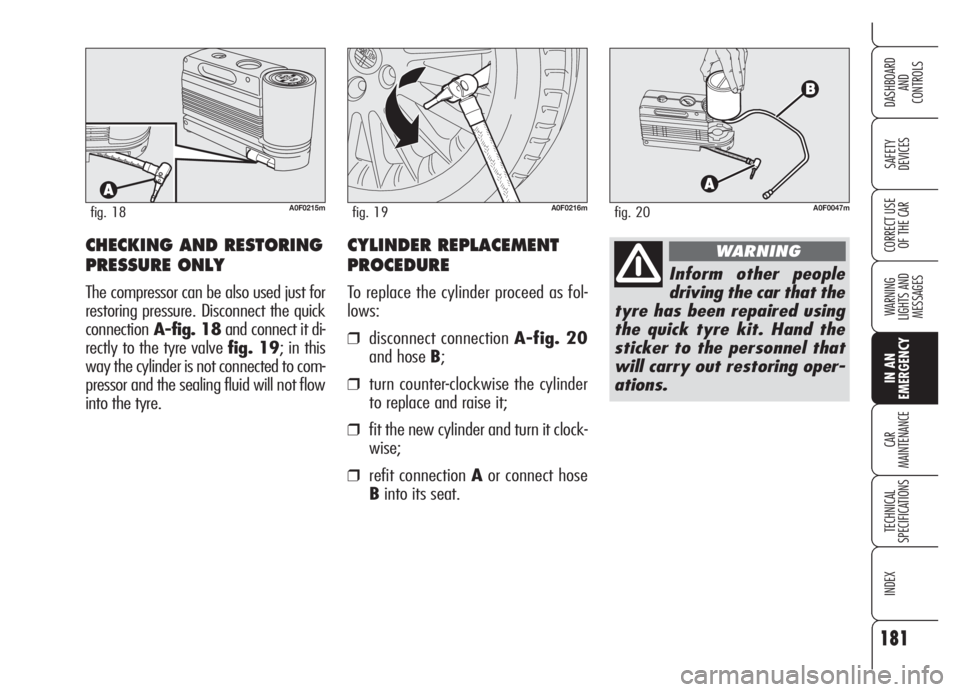
CHECKING AND RESTORING
PRESSURE ONLY
The compressor can be also used just for
restoring pressure. Disconnect the quick
connectionA-fig. 18and connect it di-
rectly to the tyre valve fig. 19; in this
way the cylinder is not connected to com-
pressor and the sealing fluid will not flow
into the tyre.
A0F0047mfig. 20
Inform other people
driving the car that the
tyre has been repaired using
the quick tyre kit. Hand the
sticker to the personnel that
will carry out restoring oper-
ations.
WARNINGCYLINDER REPLACEMENT
PROCEDURE
To replace the cylinder proceed as fol-
lows:
❒disconnect connection A-fig. 20
and hose B;
❒turn counter-clockwise the cylinder
to replace and raise it;
❒fit the new cylinder and turn it clock-
wise;
❒refit connection Aor connect hose
Binto its seat.
Page 184 of 270
183
SAFETY
DEVICES
WARNING
LIGHTS AND
MESSAGES
IN AN
EMERGENCY
CAR
MAINTENANCE
TECHNICAL
SPECIFICATIONS
INDEX
DASHBOARD
AND
CONTROLS
CORRECT USE
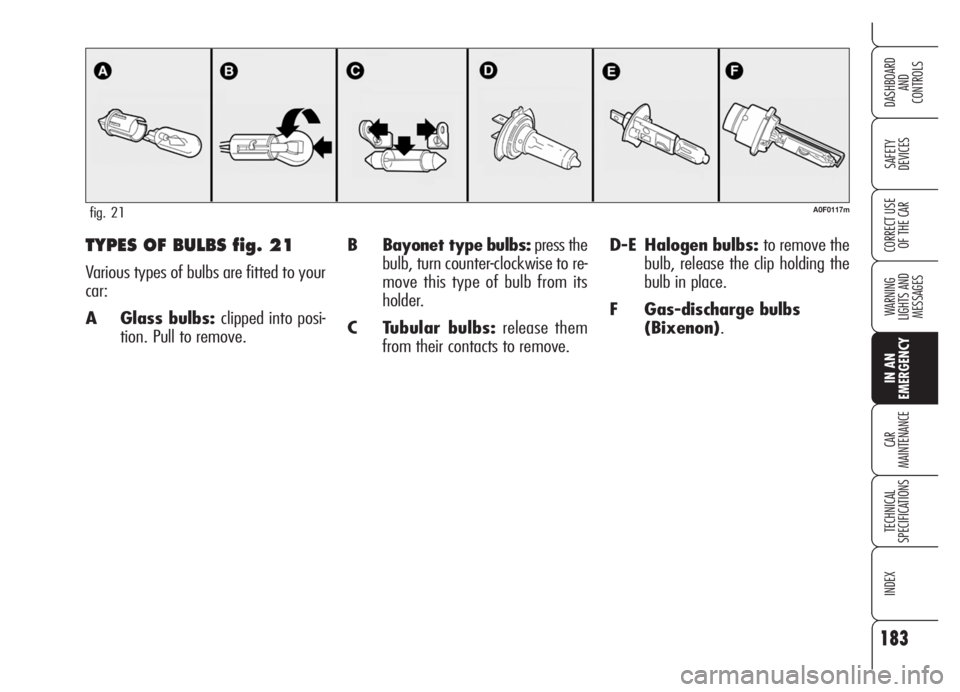
OF THE CARB Bayonet type bulbs:press the
bulb, turn counter-clockwise to re-
move this type of bulb from its
holder.
C Tubular bulbs:release them
from their contacts to remove.D-E Halogen bulbs: to remove the
bulb, release the clip holding the
bulb in place.
F Gas-discharge bulbs
(Bixenon).TYPES OF BULBS fig. 21
Various types of bulbs are fitted to your
car:
A Glass bulbs: clipped into posi-
tion. Pull to remove.
A0F0117mfig. 21
Page 186 of 270
185
SAFETY
DEVICES
WARNING
LIGHTS AND
MESSAGES
IN AN
EMERGENCY
CAR
MAINTENANCE
TECHNICAL
SPECIFICATIONS
INDEX
DASHBOARD
AND
CONTROLS
CORRECT USE
OF THE CAR
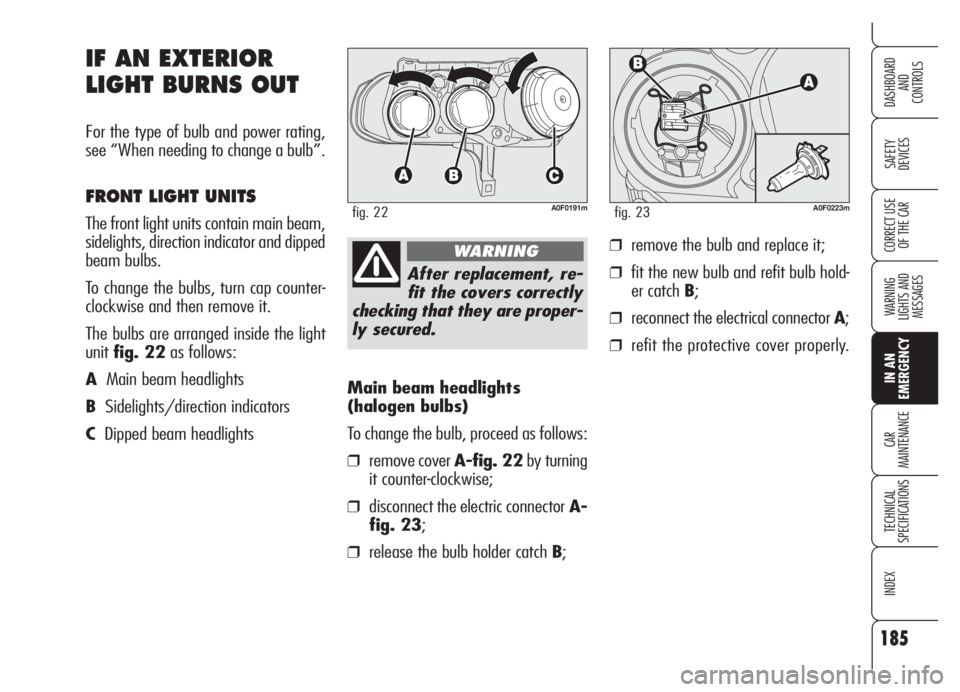
Main beam headlights
(halogen bulbs)
To change the bulb, proceed as follows:
❒remove cover A-fig. 22by turning
it counter-clockwise;
❒disconnect the electric connectorA-
fig. 23;
❒release the bulb holder catch B;
IF AN EXTERIOR
LIGHT BURNS OUT
For the type of bulb and power rating,
see “When needing to change a bulb”.
FRONT LIGHT UNITS
The front light units contain main beam,
sidelights, direction indicator and dipped
beam bulbs.
To change the bulbs, turn cap counter-
clockwise and then remove it.
The bulbs are arranged inside the light
unitfig. 22as follows:
AMain beam headlights
BSidelights/direction indicators
CDipped beam headlights
A0F0191mfig. 22
After replacement, re-
fit the covers correctly
checking that they are proper-
ly secured.
WARNING
A0F0223mfig. 23
❒remove the bulb and replace it;
❒fit the new bulb and refit bulb hold-
er catch B;
❒reconnect the electrical connector A;
❒refit the protective cover properly.
Page 187 of 270
186
SAFETY
DEVICES
WARNING
LIGHTS AND
MESSAGES
IN AN
EMERGENCY
CAR
MAINTENANCE
TECHNICAL
SPECIFICATIONS
INDEX
DASHBOARD
AND
CONTROLS
CORRECT USE
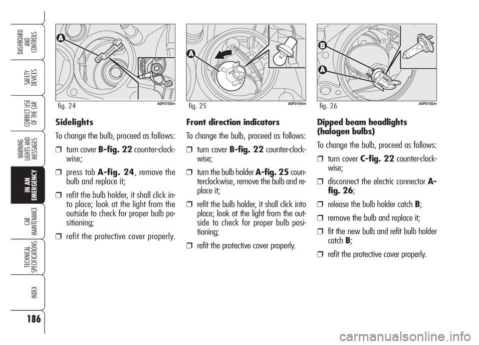
OF THE CARSidelights
To change the bulb, proceed as follows:
❒turn cover B-fig. 22counter-clock-
wise;
❒press tab A-fig. 24, remove the
bulb and replace it;
❒refit the bulb holder, it shall click in-
to place; look at the light from the
outside to check for proper bulb po-
sitioning;
❒refit the protective cover properly.
A0F0193mfig. 24A0F0194mfig. 25A0F0192mfig. 26
Front direction indicators
To change the bulb, proceed as follows:
❒turn cover B-fig. 22counter-clock-
wise;
❒turn the bulb holder A-fig. 25coun-
terclockwise, remove the bulb and re-
place it;
❒refit the bulb holder, it shall click into
place; look at the light from the out-
side to check for proper bulb posi-
tioning;
❒refit the protective cover properly.Dipped beam headlights
(halogen bulbs)
To change the bulb, proceed as follows:
❒turn cover C-fig. 22counter-clock-
wise;
❒disconnect the electric connector A-
fig. 26;
❒release the bulb holder catch B;
❒remove the bulb and replace it;
❒fit the new bulb and refit bulb holder
catchB;
❒refit the protective cover properly.