radio Alfa Romeo Brera/Spider 2008 Owner handbook (in English)
[x] Cancel search | Manufacturer: ALFA ROMEO, Model Year: 2008, Model line: Brera/Spider, Model: Alfa Romeo Brera/Spider 2008Pages: 270, PDF Size: 3.93 MB
Page 10 of 270
9
SAFETY
DEVICES
WARNING
LIGHTS AND
MESSAGES
IN AN
EMERGENCY
CAR
MAINTENANCE
TECHNICAL
SPECIFICATIONS
INDEX
DASHBOARD
AND
CONTROLS
CORRECT USE
OF THE CAR
THE ALFA ROMEO
CODE SYSTEM
To further protect you car from theft, it
has been fitted with an engine immo-
bilising system. This system is auto-
matically activated when the electronic
key is removed.
An electronic device, in fact, is fitted in
each electronic key grip. The device
transmits a radio-frequency signal when
the engine is started through a special
aerial built into the ignition switch on the
dashboard. The modulated signal, which
changes each time the engine is start-
ed, is the “password”, by means of
which the control unit recognises the
electronic key and enables to start the
engine.
SYMBOLS
Special coloured labels have been at-
tached near or actually on some of the
components of your car. These labels
bear symbols that remind you of the pre-
cautions to be taken as regards that par-
ticular component.
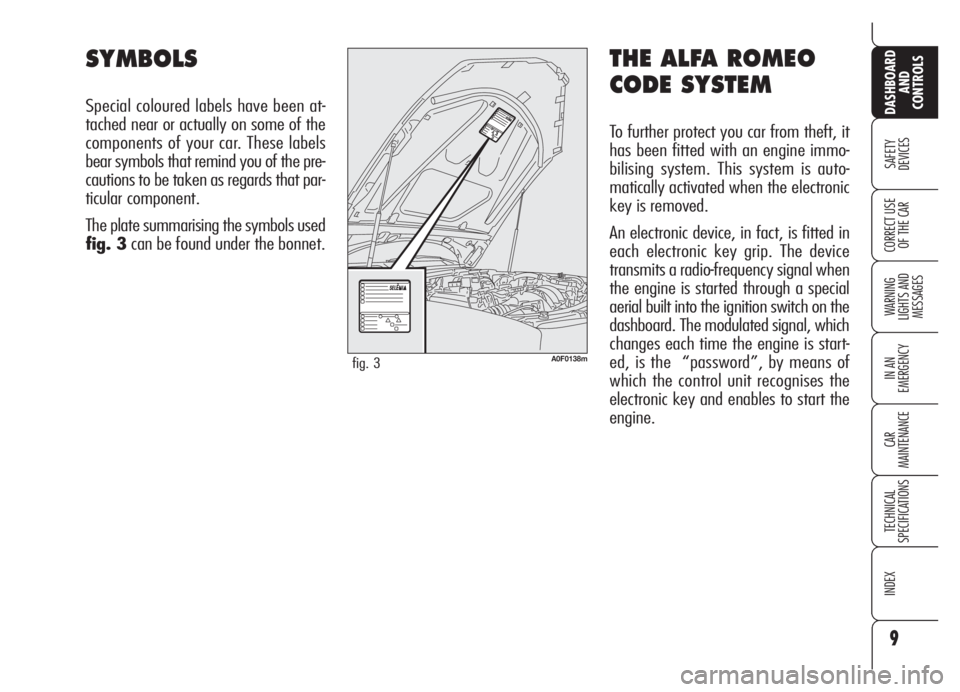
The plate summarising the symbols used
fig. 3can be found under the bonnet.
A0F0138mfig. 3
Page 13 of 270
12
SAFETY
DEVICES
WARNING
LIGHTS AND
MESSAGES
IN AN
EMERGENCY
CAR
MAINTENANCE
TECHNICAL
SPECIFICATIONS
INDEX
DASHBOARD
AND
CONTROLS
CORRECT USE
OF THE CARReplacing the battery of the
electronic key
If when pressing button
Ë,Á, or `,
control given is refused or failing, the
battery should be replaced with an
equivalent one that can be purchased at
common stores.
To be sure that the battery is to be re-
placed, try again to press buttons
Ë,
Á, or `with another electronic key.
When closing the tailgate again, pro-
tection sensors are restored and direc-
tion indicators will flash once. IMPORTANT Never expose the elec-
tronic key to direct sunlight: risk of dam-
ages.
IMPORTANTRemote control fre-
quency may be disturbed by radio trans-
missions outside the car (e.g. mobile
phones, hams, etc…). In this event re-
mote control may be failing.
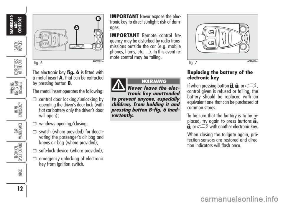
The electronic key fig. 6 is fitted with
a metal insert A, that can be extracted
by pressing button B.
The metal insert operates the following:
❒central door locking/unlocking by
operating the driver’s door lock (with
flat car battery only the driver’s door
will open);
❒windows opening/closing;
❒switch (where provided) for deacti-
vating the passenger’s air bag and
knees air bag (where provided);
❒safe-lock device (where provided);
❒emergency unlocking of electronic
key from ignition switch.
A0F0022mfig. 6
Never leave the elec-
tronic key unattended
to prevent anyone, especially
children, from holding it and
pressing button B-fig. 6 inad-
vertently.
WARNING
A0F0021mfig. 7
Page 20 of 270
19
SAFETY
DEVICES
WARNING
LIGHTS AND
MESSAGES
IN AN
EMERGENCY
CAR
MAINTENANCE
TECHNICAL
SPECIFICATIONS
INDEX
DASHBOARD
AND
CONTROLS
CORRECT USE
OF THE CAR
IGNITION
DEVICE
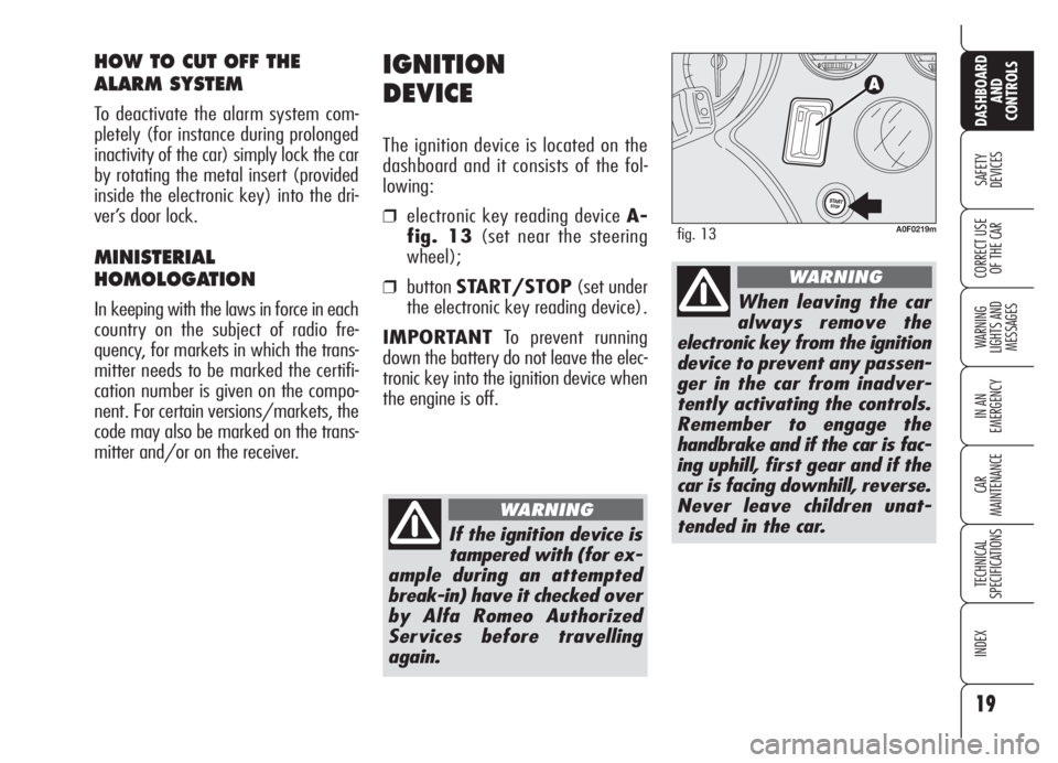
The ignition device is located on the
dashboard and it consists of the fol-
lowing:
❒electronic key reading device A-
fig. 13(set near the steering
wheel);
❒buttonSTART/STOP(set under
the electronic key reading device).
IMPORTANTTo prevent running
down the battery do not leave the elec-
tronic key into the ignition device when
the engine is off.
HOW TO CUT OFF THE
ALARM SYSTEM
To deactivate the alarm system com-
pletely (for instance during prolonged
inactivity of the car) simply lock the car
by rotating the metal insert (provided
inside the electronic key) into the dri-
ver’s door lock.
MINISTERIAL
HOMOLOGATION
In keeping with the laws in force in each
country on the subject of radio fre-
quency, for markets in which the trans-
mitter needs to be marked the certifi-
cation number is given on the compo-
nent. For certain versions/markets, the
code may also be marked on the trans-
mitter and/or on the receiver.
A0F0219mfig. 13
If the ignition device is
tampered with (for ex-
ample during an attempted
break-in) have it checked over
by Alfa Romeo Authorized
Services before travelling
again.
WARNING
When leaving the car
always remove the
electronic key from the ignition
device to prevent any passen-
ger in the car from inadver-
tently activating the controls.
Remember to engage the
handbrake and if the car is fac-
ing uphill, first gear and if the
car is facing downhill, reverse.
Never leave children unat-
tended in the car.
WARNING
Page 26 of 270
25
SAFETY
DEVICES
WARNING
LIGHTS AND
MESSAGES
IN AN
EMERGENCY
CAR
MAINTENANCE
TECHNICAL
SPECIFICATIONS
INDEX
DASHBOARD
AND
CONTROLS
CORRECT USE
OF THE CAR
AUTOMATIC INSTRUMENT
PANEL LIGHT DIMMER
To give max. visibility and comfort un-
der whatever driving conditions (e.g.:
lights on in daylight, tunnels, etc…), the
speedometer is fitted with a sensor for
adjusting automatically, after fitting the
electronic key into the ignition device and
pressing button START/STOP, the
light intensity of the instrument panel dis-
play, sound system display, climate con-
trol system display, radionavigation sys-
tem display (where provided), and in-
struments (i.e.: fuel level gauge, engine
oil temperature gauge for petrol versions
or turbocharger pressure gauge for diesel
versions, and engine coolant temperature
gauge).
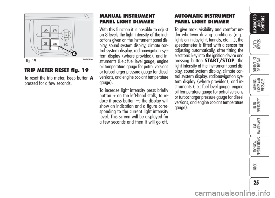
TRIP METER RESET fig. 19
To reset the trip meter, keep button A
pressed for a few seconds.
MANUAL INSTRUMENT
PANEL LIGHT DIMMER
With this function it is possible to adjust
on 8 levels the light intensity of the indi-
cations given on the instrument panel dis-
play, sound system display, climate con-
trol system display, radionavigation sys-
tem display (where provided), and in-
struments (i.e.: fuel level gauge, engine
oil temperature gauge for petrol versions
or turbocharger pressure gauge for diesel
versions, and engine coolant temperature
gauge).
To increase light intensity press briefly
button+on the left-hand stalk, to re-
duce it press button –: the display will
show an indication and a figure corre-
sponding to the current light intensity
level. This screen will be displayed for
a few seconds and then it will go off.
A0F0072mfig. 19
Page 30 of 270
29
SAFETY
DEVICES
WARNING
LIGHTS AND
MESSAGES
IN AN
EMERGENCY
CAR
MAINTENANCE
TECHNICAL
SPECIFICATIONS
INDEX
DASHBOARD
AND
CONTROLS
CORRECT USE
OF THE CAR
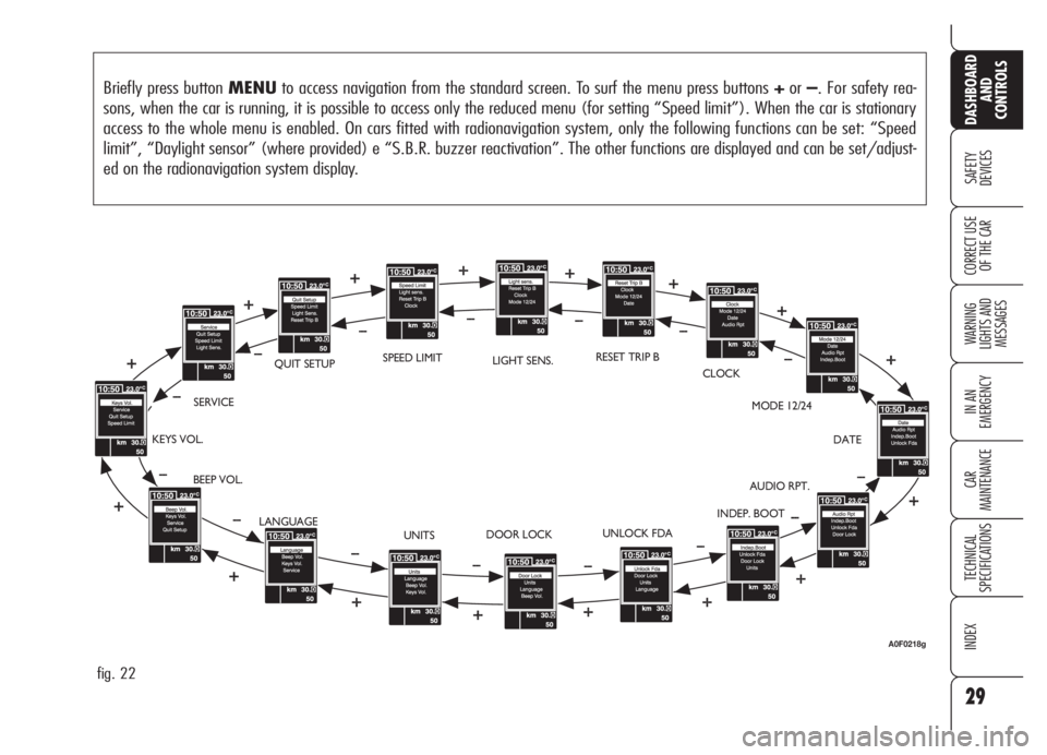
Briefly press button MENUto access navigation from the standard screen. To surf the menu press buttons +or–. For safety rea-
sons, when the car is running, it is possible to access only the reduced menu (for setting “Speed limit”). When the car is stationary
access to the whole menu is enabled. On cars fitted with radionavigation system, only the following functions can be set: “Speed
limit”, “Daylight sensor” (where provided) e “S.B.R. buzzer reactivation”. The other functions are displayed and can be set/adjust-
ed on the radionavigation system display.
fig. 22
BEEP VOL.SERVICEQUIT SETUPLIGHT SENS.RESET TRIP B
CLOCK
MODE 12/24
DATE
AUDIO RPT.
INDEP. BOOT
UNLOCK FDA
DOOR LOCK
UNITS KEYS VOL.
LANGUAGESPEED LIMIT
A0F0218g
Page 33 of 270
32
SAFETY
DEVICES
WARNING
LIGHTS AND
MESSAGES
IN AN
EMERGENCY
CAR
MAINTENANCE
TECHNICAL
SPECIFICATIONS
INDEX
DASHBOARD
AND
CONTROLS
CORRECT USE
OF THE CAR
Setting the date (Date)
This function enables to update the date
(year - month - day).
Proceed as follows:
❒briefly press button MENU: “year”
will flash on the display;
❒press button +or–for setting as re-
quired;
❒briefly press button MENU:
“month” will flash on the display;
❒press button +or–for setting as re-
quired;
❒briefly press button MENU: “day”
will flash on the display;
❒press button +or–for setting as re-
quired;IMPORTANTEvery press (pulse) on
the button +/–increases/decreases by
one unit. Keeping button +/–pressed
obtains fast increase/decrease. When
you are near the required setting com-
plete adjustment with single presses.
❒briefly press button MENUto go
back to the menu screen or press the
button for long to go back to the
standard screen.
Audio Info Repetition
(Audio Rpt.) (where provided)
This function enables to display sound
system information.
❒Radio: selected radio station fre-
quency or RDS message, automatic
tuning activation or AutoSTore;
❒audio CD, MP3 Cd: selected track
number;
❒CD Changer: CD number and track
number;To activate/deactivate (ON/OFF) in-
fo displaying proceed as follows:
❒briefly press button MENU: the dis-
play will show ONorOFF(ac-
cording to previous setting);
❒press button +or–for setting as re-
quired;
❒briefly press button MENUto go
back to the menu screen or press the
button for long to go back to the
standard screen.
According to the audio source selected,
below the time will be displayed the
symbol of the current source.
Page 106 of 270
105
SAFETY
DEVICES
WARNING
LIGHTS AND
MESSAGES
IN AN
EMERGENCY
CAR
MAINTENANCE
TECHNICAL
SPECIFICATIONS
INDEX
DASHBOARD
AND
CONTROLS
CORRECT USE
OF THE CAR
RADIO TRANSMITTERS AND
CELLULAR TELEPHONES
Mobile phones and other radio trans-
ceiver equipment (e.g.: HAM radio sys-
tems and the like) shall not be used in-
side the car unless a separate aerial is
mounted.
IMPORTANTThe use of mobile
phones, HAM radio systems or other
similar devices inside the passenger
compartment (without separate aerial)
may cause electronic systems equipping
the car to malfunction. This could com-
promise safety in addition to constitut-
ing a potential hazard for the passen-
gers.
In addition, transmission and reception
of these devices may be affected by the
shielding effect of the car body.
As concerns the use of mobile phones
(GSM, GPRS, UMTS) with homologa-
tion , keep strictly to the mobile
phone manufacturer’s specifications.
ACCESSORIES
PURCHASED
BY THE OWNER
If after buying the car, you decide to in-
stall electrical accessories that require a
permanent electric supply (alarm, satel-
lite antitheft system, etc.) or accessories
that in any case burden the electric sup-
ply, contact Alfa Romeo Authorized Ser-
vices, whose qualified personnel, besides
suggesting the most suitable devices be-
longing to Lineaccessori Alfa Romeo, will
also evaluate the overall electric absorp-
tion, checking whether the car’s electric
system is able to withstand the load re-
quired, or whether it needs to be inte-
grated with a more powerful battery.
Take care when fitting
additional spoilers, al-
loy rims and non-standard
wheel caps: they might reduce
ventilation of the brakes, thus
their efficiency, during abrupt
and repeated braking, or long
downhill slopes. Make sure
that nothing (mats, etc.) gets
in the way of the pedals when
they are pushed down.
WARNING
INSTALLATION OF
ELECTRIC/ELECTRONIC
DEVICES
Electric/electronic devices installed af-
ter buying the car or in aftermarket shall
bear the and marking:
Fiat Auto S.p.A. authorizes the installa-
tion of transceivers provided that instal-
lation is carried out at a specialized
shop, workmanlike performed and in
compliance with manufacturer’s speci-
fications.
IMPORTANTInstallation of devices
resulting in modifications of car charac-
teristics may cause driving license seiz-
ing by traffic agents and also the lapse
of the warranty as concerns defects due
to the abovementioned modification or
traceable back to it directly or indirectly.
Fiat Auto S.p.A. declines all responsibil-
ity for damages caused by the installa-
tion of non-genuine accessories or not
recommended by Fiat Auto S.p.A. and
installed not in compliance with the spec-
ified requirements.
Page 110 of 270
109
SAFETY
DEVICES
WARNING
LIGHTS AND
MESSAGES
IN AN
EMERGENCY
CAR
MAINTENANCE
TECHNICAL
SPECIFICATIONS
INDEX
DASHBOARD
AND
CONTROLS
CORRECT USE
OF THE CAR
TYRE PRESSURE MONITORING SYSTEM -
T.P.M.S. (where provided)
(optional for versions/markets
where applicable)
The car can be equipped with the
T.P.M.S. (Tyre Pressure Monitoring Sys-
tem). This system consists of a radio-fre-
quency sensor, installed on each wheel
(on the rim inside the tyre) that sends
pressure information to the control unit.IMPORTANT NOTES
Failure indications will not be stored and
therefore will not be displayed when
turning the engine off and on again. If
failure persists, the control unit will send
warning indications to the instrument
panel only after a few seconds when the
car is moving.
Tyre pressure should be checked with
tyres cold. Should it become necessary
for whatever reason to check pressure
with hot tyres, do not reduce pressure
although it is higher than the prescribed
value but repeat the check when tyres
are cold (see section “Wheels” in sec-
tion “Technical Specifications”).T.P.M.S. cannot indicate sudden tyre
pressure drops (e.g.: tyre burst). In this
event, brake the car cautiously and
avoid sudden steering.
The T.P.M.S. system requires special
equipment. Consult Alfa Romeo Autho-
rized Services to know what type of ac-
cessories are compatible with the sys-
tem (wheels, wheel caps, etc.). Using
other accessories could cause system
malfunctioning. Due to inflation valve
special characteristics, use only tyre re-
pair sealants approved by Alfa Romeo;
other sealants could cause system mal-
functioning.
The T.P.M.S. does not
exempt the driver from
checking tyre pressure, includ-
ing the space-saver spare
wheel (where provided) at
regular intervals.
WARNING
Page 111 of 270
110
SAFETY
DEVICES
WARNING
LIGHTS AND
MESSAGES
IN AN
EMERGENCY
CAR
MAINTENANCE
TECHNICAL
SPECIFICATIONS
INDEX
DASHBOARD
AND
CONTROLS
CORRECT USE
OF THE CAR
If the car is fitted with T.P.M.S. system,
when changing a tyre, change also the
rubber seal of the valve and the fas-
tening ring of the sensor. Contact Alfa
Romeo Authorized Services.
Strong radio-frequency disturbances
could inhibit proper TPMS system oper-
ation. This condition is indicated by a
dedicated massage on the display. This
indication will go off automatically as
soon as the radio-frequency disturbance
ceases.If after repairing a punctured tyre with
the Fix&Go automatic kit and restoring
the initial conditions the flat tyre warn-
ing light continues to stay on, contact
Alfa Romeo Authorized Services.
Tyre pressure could change according to
outside temperature. For this reason the
T.P.M.S. system could temporarily indi-
cate low tyre pressure. In this event
check pressure with cold tyres and re-
store proper inflation values if required.If the car is fitted with T.P.M.S. system,
tyre and/or rim removal and refitting
operations involve special precautions;
to prevent damages or wrong sensor re-
fitting, contact Alfa Romeo Authorized
Services to have tyre and/or rim
changed.
Page 201 of 270
200
SAFETY
DEVICES
WARNING
LIGHTS AND
MESSAGES
IN AN
EMERGENCY
CAR
MAINTENANCE
TECHNICAL
SPECIFICATIONS
INDEX
DASHBOARD
AND
CONTROLS
CORRECT USE
OF THE CAR
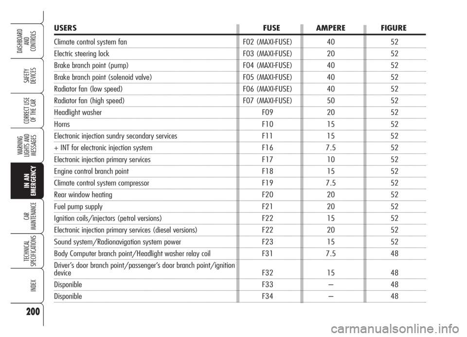
USERS FUSE AMPERE FIGURE
Climate control system fan F02 (MAXI-FUSE) 40 52
Electric steering lock F03 (MAXI-FUSE) 20 52
Brake branch point (pump) F04 (MAXI-FUSE) 40 52
Brake branch point (solenoid valve) F05 (MAXI-FUSE) 40 52
Radiator fan (low speed) F06 (MAXI-FUSE) 40 52
Radiator fan (high speed) F07 (MAXI-FUSE) 50 52
Headlight washer F09 20 52
Horns F10 15 52
Electronic injection sundry secondary services F11 15 52
+ INT for electronic injection system F16 7.5 52
Electronic injection primary services F17 10 52
Engine control branch point F18 15 52
Climate control system compressor F19 7.5 52
Rear window heating F20 20 52
Fuel pump supply F21 20 52
Ignition coils/injectors (petrol versions) F22 15 52
Electronic injection primary services (diesel versions) F22 20 52
Sound system/Radionavigation system power F23 15 52
Body Computer branch point/Headlight washer relay coil F31 7.5 48
Driver’s door branch point/passenger’s door branch point/ignition
device F32 15 48
Disponible F33 – 48
Disponible F34 – 48