Alfa Romeo Giulia 2018 Owner's Manual
Manufacturer: ALFA ROMEO, Model Year: 2018, Model line: Giulia, Model: Alfa Romeo Giulia 2018Pages: 260, PDF Size: 6 MB
Page 171 of 260
Transporting Passengers
Warning!
It is extremely dangerous to leave
children in a parked vehicle when the
temperature outside is very high. The heat
inside the passenger compartment may
have serious, or even fatal, consequences.
Never travel in the trunk of the vehicle.
In the event of an accident, anyone inside
the trunk would be at greater risk of serious
or even fatal injury.
Ensure that all the occupants of the
vehicle wear their seat belts correctly and
that any children are positioned correctly on
the dedicated child restraint systems.
Transporting Animals
The intervention of the airbags may be
dangerous for an animal on the front
seat. It is therefore advised to arrange
animals on the rear seat inside dedicated
cages restrained by the vehicle’s seat
belts.
Keep in mind that, in the event of a
sudden braking or an accident, an
inadequately restrained animal may be
projected within the passenger
compartment, risking injury to the animal
itself and the other occupants of the
vehicle.
Exhaust Gas
Exhaust emissions are very dangerous,
and may be lethal. They contain carbon
monoxide, a colorless, odorless gas
which can cause fainting and poisoning if
inhaled.
To avoid inhaling carbon monoxide, take
the following measures:
Do not keep the engine running in
closed spaces.
If, for some reason (e.g. transporting
bulky loads), it is necessary to drive with
the trunk open, close all the windows and
run the climate control fan at maximum
speed. DO NOT activate air recirculation
mode.
Should it be necessary to stay in the
stationary vehicle with engine running,
adjust the ventilation/heating system
and operate the fan in such a way that
outside air will enter the passenger
compartment. Activate the maximum fan
speed.
Maintenance of the exhaust system
provides the best protection against
leaks of carbon monoxide into the
passenger compartment.
Should an unusual noise from the exhaust
system or the presence of exhaust gas in
the passenger compartment be
identified, or if the underbody or rear
section of the vehicle is damaged, have the entire exhaust system and bodywork
areas checked to identify any
components which are broken, damaged,
worn or have moved from their correct
fitting position. If any of these things
occur, contact your authorized dealer.
Open welding or loose connections may
permit exhaust gas to enter the
passenger compartment.
Check the exhaust system each time the
vehicle is raised for lubrication or oil
change operations. Replace the
components if necessary, contact your
authorized dealer.
Performance
This vehicle is equipped with an engine
capable of delivering exceptionally fast
acceleration and speed:
Peak power: 505 HP at 6500 rpm.
Peak torque: 443 ft-lbs at
2500–5000 rpm.
Top speed: 191 mph (307 km/h).
Acceleration from 0 to 60 mph
(0 to 100 km/h): 3.8 seconds.
For safe driving, it is essential, particularly
during the first days of use, to get to know
the car by driving carefully and gradually
discovering its performance.
169
Page 172 of 260
Brakes
The car braking system may be available
with four carbon-ceramic material brake
discs, one on each wheel.
In order to guarantee the maximum
braking capacity for the first use, Alfa
Romeo performs a "run-in" procedure for
discs and pads directly at the factory.
The use of carbon-ceramic material
brake discs guarantees braking features
(better deceleration/pedal load ratio,
braking distances, fading resistance)
proportional to the dynamic features of
the car in addition to considerably
decreasing the unsprung component
weight.
The materials used and the structural
features of the system could generate
unusual noises which have absolutely no
adverse effect on correct operation and
reliability of the braking system.
Greater pressure may need to be applied
to the brake pedal the first time to keep
the same braking capacities in presence
of condensation or salt on the braking
surfaces, for example after washing or if
the car is not used for a long time.
Note:Given the high technological level
of this system, any servicing on it must be
performed by your authorized dealer
which exclusively has the skills needed
for the repair operations. In case of intensive, high-performance
use of the car, have the efficiency of the
carbon-ceramic material braking system
inspected as shown on the Maintenance
Plan at your authorized dealer.
Driving On Race Tracks
Before driving on a track using a racing
style, it is necessary to:
Attend a race track driving course.
Check the liquid levels in the engine
compartment. For more information, see
the “Checking Levels” section in the
“Servicing And Maintenance” chapter.
Have the car inspected at your
authorized dealer.
Remember that the car was not designed
to be driven exclusive on the race track
and that this use increases stress and
component wear.
Preheating The Carbon Ceramic
Material Brake Discs
The brake discs must be warmed up to
make them fully efficient. You are
advised to perform the following
procedure:
Brake nine times from 80 mph to
18 mph (130 km/h to 30 km/h) with
deceleration equal to 0.7g (the
longitudinal acceleration value is shown
on the instrument panel display by
setting RACE mode and selecting the “Performance” page) with 20 second
intervals between brake applications;
keep the car at a speed comprised
between 37 mph and 62 mph (60 km/h
and 100 km/h) and do not brake for
4 minutes to allow the brakes to cool
down;
Then brake three times from 124 mph
to 18 mph (200 km/h to 30 km/h) with
deceleration equal to 1.1g (ABS
operation) with 30 second intervals
between brake applications; keep the car
at a speed comprised between 37 mph
and 62 mph (60 km/h and 100 km/h) and
do not brake for 5 minutes to allow the
brakes to cool down.
170
STARTING AND OPERATING
Page 173 of 260
IN CASE OF EMERGENCY
Have a flat tire or a burnt-out bulb?
At times, a problem such as these may
interfere with your driving experience.
The section on emergencies can help you
to deal with critical situations
independently.
In an emergency, we recommend that you
call the phone number found in the
Warranty Book.
You may also consider contacting an
authorized dealer.HAZARD WARNING LIGHTS.....172
BULB REPLACEMENT .........172
FUSES .................. .177
TIRE SERVICE KIT ............183
JUMP STARTING ............186
REFUELING IN EMERGENCY .....188
ENGINE OVERHEATING ........189
TOWING A DISABLED VEHICLE . . .190
TOW EYES ............... .191
ENHANCED ACCIDENT RESPONSE
SYSTEM (EARS) .............192
EVENT DATA RECORDER (EDR) . . .192
171
Page 174 of 260
HAZARD WARNING LIGHTS
The Hazard Warning switch is located in
the switch bank below the radio screen.Push the switch once to
turn the hazard warning
flashers on. When the
switch is activated, all
directional turn signals
will flash on and off to
warn oncoming traffic
of an emergency. Push the switch a
second time to turn the hazard warning
flashers off.
This is an emergency warning system and
it should not be used when the vehicle is
in motion. Use it when your vehicle is
disabled and is creating a safety hazard
for other motorists.
When you must leave the vehicle to seek
assistance, the hazard warning flashers
will continue to operate even though the
ignition is cycled to OFF.
Caution!
Prolonged use of the hazard warning
flashers may discharge the vehicle’s battery.
BULB REPLACEMENT
General Instructions
Before replacing a bulb, check the
contacts for oxidation.
Replace blown bulbs with others of the
same type and power.
After replacing a headlight bulb,
always check its alignment.
When a light is not working, check that
the corresponding fuse is intact before
changing the bulb. For the location of
fuses, refer to “Fuses” in this chapter.
Note: In some particular climate
conditions, such as low temperature,
humidity, or after washing the car, a thin
condensation layer may form on the
internal surfaces of the front and rear
headlights. This condensation will
disappear after switching on the
headlights.08016S0001EM1Hazard Warning Switch
172
IN CASE OF EMERGENCY
Page 175 of 260
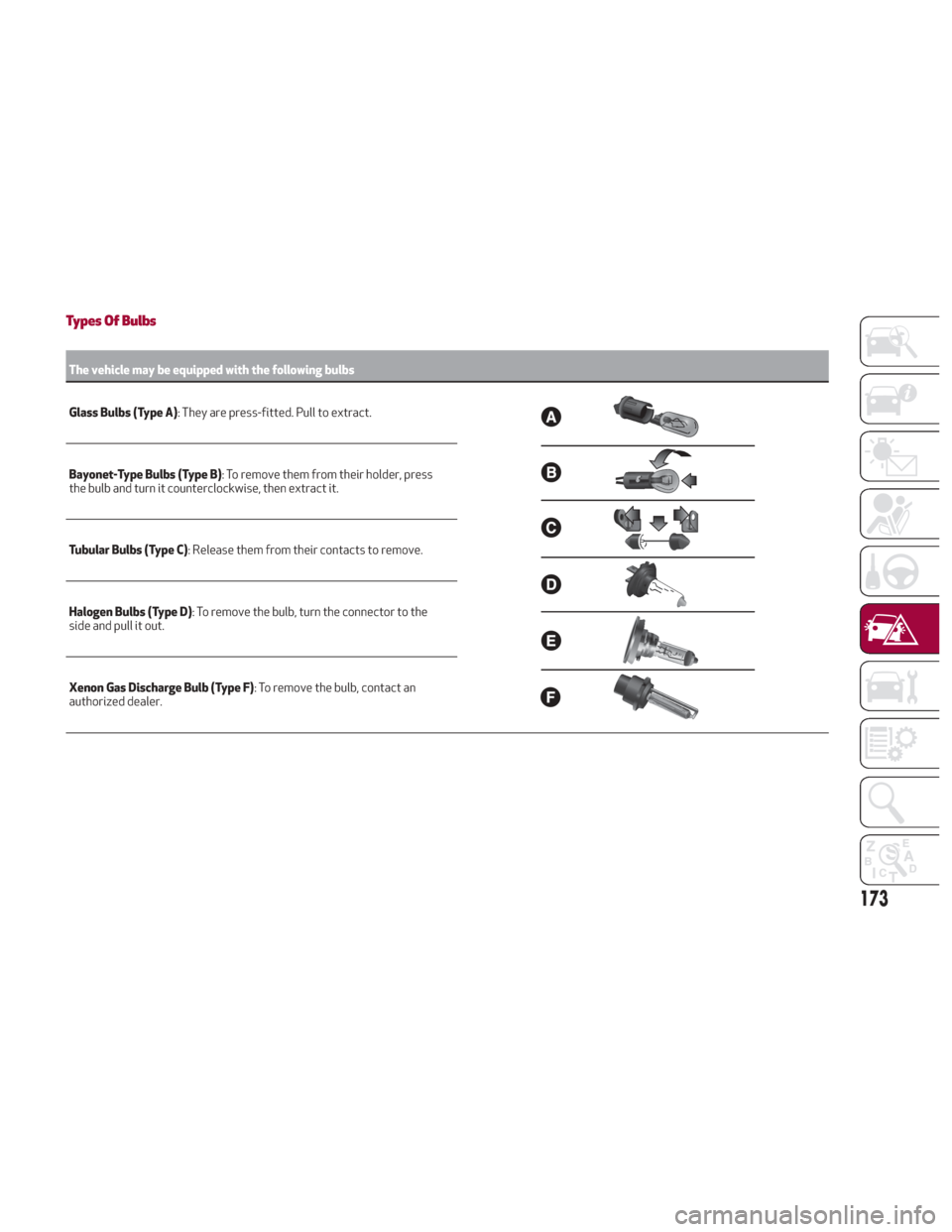
Types Of Bulbs
The vehicle may be equipped with the following bulbs
Glass Bulbs (Type A):
They are press-fitted. Pull to extract.
Bayonet-Type Bulbs (Type B) : To remove them from their holder, press
the bulb and turn it counterclockwise, then extract it.
Tubular Bulbs (Type C) : Release them from their contacts to remove.
Halogen Bulbs (Type D) : To remove the bulb, turn the connector to the
side and pull it out.
Xenon Gas Discharge Bulb (Type F) : To remove the bulb, contact an
authorized dealer.
173
Page 176 of 260
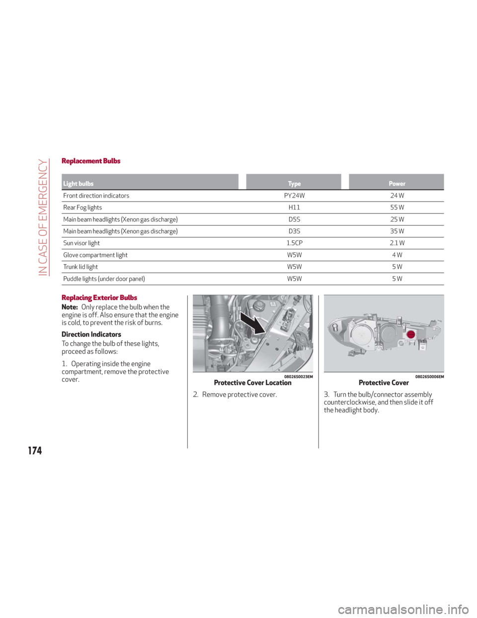
Replacement Bulbs
Light bulbsTypePower
Front direction indicators PY24W24 W
Rear
Fog lights H1155 W
Main beam headlights (Xenon gas discharge) D5S25 W
Main beam headlights (Xenon gas discharge) D3S35 W
Sun visor light 1.5CP2.1 W
Glove compartment light W5W4 W
Trunk lid light W5W5 W
Puddle lights (under door panel) W5W5 W
Replacing Exterior Bulbs
Note:Only replace the bulb when the
engine is off. Also ensure that the engine
is cold, to prevent the risk of burns.
Direction Indicators
To change the bulb of these lights,
proceed as follows:
1. Operating inside the engine
compartment, remove the protective
cover.
2. Remove protective cover. 3. Turn the bulb/connector assemblycounterclockwise, and then slide it off
the headlight body.
08026S0023EMProtective Cover Location08026S0006EMProtective Cover
174
IN CASE OF EMERGENCY
Page 177 of 260
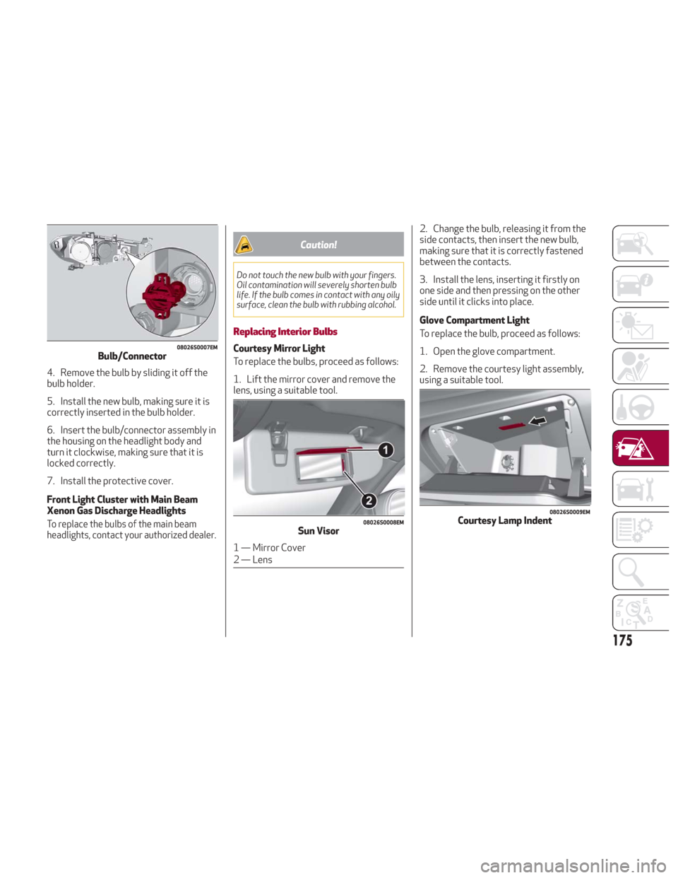
4. Remove the bulb by sliding it off the
bulb holder.
5. Install the new bulb, making sure it is
correctly inserted in the bulb holder.
6. Insert the bulb/connector assembly in
the housing on the headlight body and
turn it clockwise, making sure that it is
locked correctly.
7. Install the protective cover.
Front Light Cluster with Main Beam
Xenon Gas Discharge Headlights
To replace the bulbs of the main beam
headlights, contact your authorized dealer.
Caution!
Do not touch the new bulb with your fingers.
Oil contamination will severely shorten bulb
life. If the bulb comes in contact with any oily
surface, clean the bulb with rubbing alcohol.
Replacing Interior Bulbs
Courtesy Mirror Light
To replace the bulbs, proceed as follows:
1. Lift the mirror cover and remove the
lens, using a suitable tool.2. Change the bulb, releasing it from the
side contacts, then insert the new bulb,
making sure that it is correctly fastened
between the contacts.
3. Install the lens, inserting it firstly on
one side and then pressing on the other
side until it clicks into place.
Glove Compartment Light
To replace the bulb, proceed as follows:
1. Open the glove compartment.
2. Remove the courtesy light assembly,
using a suitable tool.08026S0007EMBulb/Connector
08026S0008EMSun Visor
1 — Mirror Cover
2 — Lens
08026S0009EMCourtesy Lamp Indent
175
Page 178 of 260
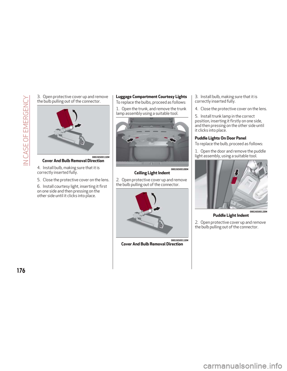
3. Open protective cover up and remove
the bulb pulling out of the connector.
4. Install bulb, making sure that it is
correctly inserted fully.
5. Close the protective cover on the lens.
6. Install courtesy light, inserting it first
on one side and then pressing on the
other side until it clicks into place.Luggage Compartment Courtesy Lights
To replace the bulbs, proceed as follows:
1. Open the trunk, and remove the trunk
lamp assembly using a suitable tool.
2. Open protective cover up and remove
the bulb pulling out of the connector.
3. Install bulb, making sure that it is
correctly inserted fully.
4. Close the protective cover on the lens.
5. Install trunk lamp in the correct
position, inserting it firstly on one side,
and then pressing on the other side until
it clicks into place.
Puddle Lights On Door Panel
To replace the bulb, proceed as follows:
1. Open the door and remove the puddle
light assembly, using a suitable tool.
2. Open protective cover up and remove
the bulb pulling out of the connector.
08026S0011EMCover And Bulb Removal Direction
08026S0010EMCeiling Light Indent
08026S0011EMCover And Bulb Removal Direction
08026S0012EMPuddle Light Indent
176
IN CASE OF EMERGENCY
Page 179 of 260
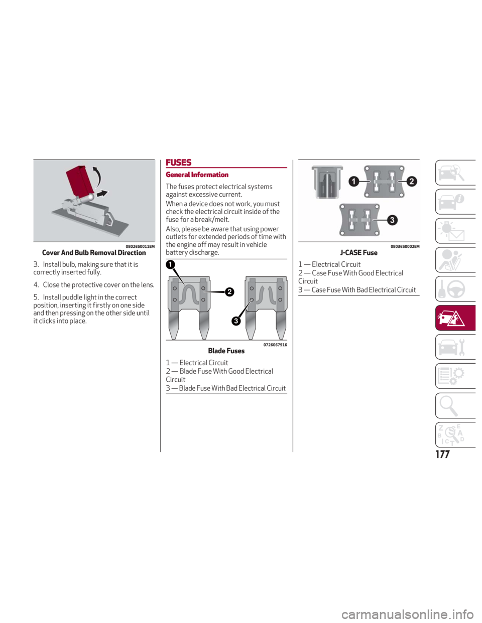
3. Install bulb, making sure that it is
correctly inserted fully.
4. Close the protective cover on the lens.
5. Install puddle light in the correct
position, inserting it firstly on one side
and then pressing on the other side until
it clicks into place.
FUSES
General Information
The fuses protect electrical systems
against excessive current.
When a device does not work, you must
check the electrical circuit inside of the
fuse for a break/melt.
Also, please be aware that using power
outlets for extended periods of time with
the engine off may result in vehicle
battery discharge.
08026S0011EMCover And Bulb Removal Direction
2
3
1
0726067916Blade Fuses
1 — Electrical Circuit
2 — Blade Fuse With Good Electrical
Circuit
3
— Blade Fuse With Bad Electrical Circuit
08036S0002EMJ-CASE Fuse
1 — Electrical Circuit
2 — Case Fuse With Good Electrical
Circuit
3
— Case Fuse With Bad Electrical Circuit
177
Page 180 of 260
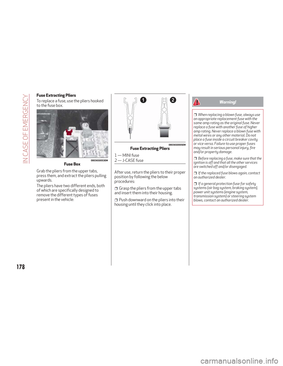
Fuse Extracting Pliers
To replace a fuse, use the pliers hooked
to the fuse box.
Grab the pliers from the upper tabs,
press them, and extract the pliers pulling
upwards.
The pliers have two different ends, both
of which are specifically designed to
remove the different types of fuses
present in the vehicle:After use, return the pliers to their proper
position by following the below
procedures:
Grasp the pliers from the upper tabs
and insert them into their housing.
Push downward on the pliers into their
housing until they click into place.
Warning!
When replacing a blown fuse, always use
an appropriate replacement fuse with the
same amp rating as the original fuse. Never
replace a fuse with another fuse of higher
amp rating. Never replace a blown fuse with
metal wires or any other material. Do not
place a fuse inside a circuit breaker cavity
or vice versa. Failure to use proper fuses
may result in serious personal injury, fire
and/or property damage.
Before replacing a fuse, make sure that the
ignition is off and that all the other services
are switched off and/or disengaged.
If the replaced fuse blows again, contact
an authorized dealer.
If a general protection fuse for safety
systems (air bag system, braking system),
power unit systems (engine system,
transmission system) or steering system
blows, contact an authorized dealer.
08036S0053EMFuse Box
08036S0005EMFuse Extracting Pliers
1 — MINI fuse
2 — J-CASE fuse
178
IN CASE OF EMERGENCY