fuel pressure ALFA ROMEO GIULIA 2021 Owners Manual
[x] Cancel search | Manufacturer: ALFA ROMEO, Model Year: 2021, Model line: GIULIA, Model: ALFA ROMEO GIULIA 2021Pages: 284, PDF Size: 8.87 MB
Page 15 of 284
13
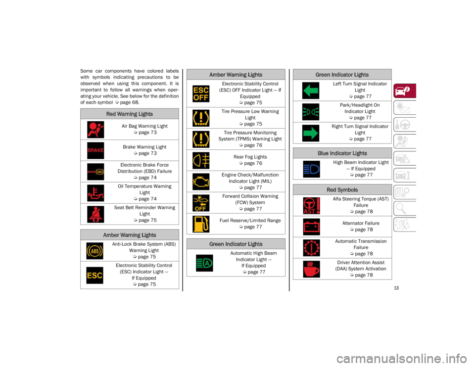
Some car components have colored labels
with symbols indicating precautions to be
observed when using this component. It is
important to follow all warnings when oper-
ating your vehicle. See below for the definition
of each symbol
Ú
page 68.
Red Warning Lights
Air Bag Warning Light
Ú
page 73
Brake Warning Light
Ú
page 73
Electronic Brake Force
Distribution (EBD) Failure
Ú
page 74
Oil Temperature Warning Light
Ú
page 74
Seat Belt Reminder Warning Light
Ú
page 75
Amber Warning Lights
Anti-Lock Brake System (ABS)
Warning Light
Ú
page 75
Electronic Stability Control (ESC) Indicator Light — If Equipped
Ú
page 75
Electronic Stability Control
(ESC) OFF Indicator Light — If Equipped
Ú
page 75
Tire Pressure Low Warning Light
Ú
page 75
Tire Pressure Monitoring
System (TPMS) Warning Light
Ú
page 76
Rear Fog Lights
Ú
page 76
Engine Check/Malfunction Indicator Light (MIL)
Ú
page 77
Forward Collision Warning (FCW) System
Ú
page 77
Fuel Reserve/Limited Range
Ú
page 77
Green Indicator Lights
Automatic High Beam
Indicator Light — If Equipped
Ú
page 77
Amber Warning Lights
Left Turn Signal Indicator
Light
Ú
page 77
Park/Headlight On Indicator Light
Ú
page 77
Right Turn Signal Indicator Light
Ú
page 77
Blue Indicator Lights
High Beam Indicator Light
— If Equipped
Ú
page 77
Red Symbols
Alfa Steering Torque (AST)
Failure
Ú
page 78
Alternator Failure
Ú
page 78
Automatic Transmission Failure
Ú
page 78
Driver Attention Assist
(DAA) System Activation
Ú
page 78
Green Indicator Lights
21_GA_OM_EN_USC_t.book Page 13
Page 16 of 284
SYMBOL GLOSSARY
14
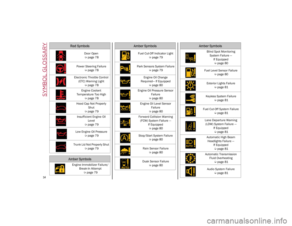
Door Open
Ú
page 78
Power Steering Failure
Ú
page 78
Electronic Throttle Control (ETC) Warning Light
Ú
page 78
Engine Coolant
Temperature Too High
Ú
page 78
Hood Cap Not Properly Shut
Ú
page 79
Insufficient Engine Oil Level
Ú
page 79
Low Engine Oil Pressure
Ú
page 79
Trunk Lid Not Properly Shut
Ú
page 79
Amber Symbols
Engine Immobilizer Failure/
Break-In Attempt
Ú
page 79
Red Symbols
Fuel Cut-Off Indicator Light
Ú
page 79
Park Sensors System Failure
Ú
page 79
Engine Oil Change
Required— If Equipped
Ú
page 80
Engine Oil Pressure Sensor Failure
Ú
page 80
Engine Oil Level Sensor Failure
Ú
page 80
Forward Collision Warning (FCW) System Failure — If Equipped
Ú
page 80
Stop/Start System Failure
Ú
page 80
Rain Sensor Failure
Ú
page 80
Dusk Sensor Failure
Ú
page 80
Amber Symbols
Blind Spot Monitoring
System Failure — If Equipped
Ú
page 80
Fuel Level Sensor Failure
Ú
page 80
Exterior Lights Failure
Ú
page 81
Keyless System Failure
Ú
page 81
Fuel Cut-Off System Failure
Ú
page 81
Lane Departure Warning (LDW) System Failure — If Equipped
Ú
page 81
Automatic High Beam Headlights Failure — If Equipped
Ú
page 81
Automatic Transmission Fluid Overheating
Ú
page 81
Audio System Failure
Ú
page 81
Amber Symbols
21_GA_OM_EN_USC_t.book Page 14
Page 73 of 284
71
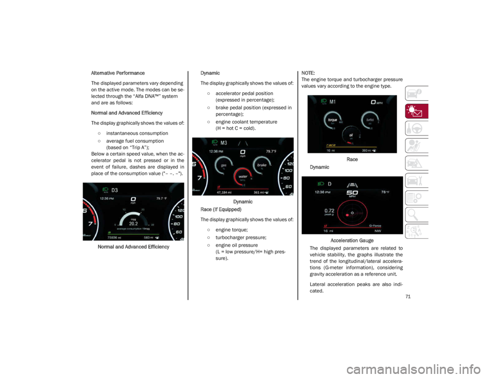
Alternative Performance
The displayed parameters vary depending
on the active mode. The modes can be se-
lected through the “Alfa DNA™” system
and are as follows:
Normal and Advanced Efficiency
The display graphically shows the values of:
○ instantaneous consumption
○ average fuel consumption (based on “Trip A”);
Below a certain speed value, when the ac -
celerator pedal is not pressed or in the
event of failure, dashes are displayed in
place of the consumption value ("– –. –").
Normal and Advanced Efficiency Dynamic
The display graphically shows the values of:
○ accelerator pedal position (expressed in percentage);
○ brake pedal position (expressed in percentage);
○ engine coolant temperature (H = hot C = cold).
Dynamic
Race (If Equipped)
The display graphically shows the values of:
○ engine torque;
○ turbocharger pressure;
○ engine oil pressure (L = low pressure/H= high pres -
sure).
NOTE:
The engine torque and turbocharger pressure
values vary according to the engine type.
Race
Dynamic
Acceleration Gauge
The displayed parameters are related to
vehicle stability, the graphs illustrate the
trend of the longitudinal/lateral accelera -
tions (G-meter information), considering
gravity acceleration as a reference unit.
Lateral acceleration peaks are also indi -
cated.
21_GA_OM_EN_USC_t.book Page 71
Page 77 of 284
75
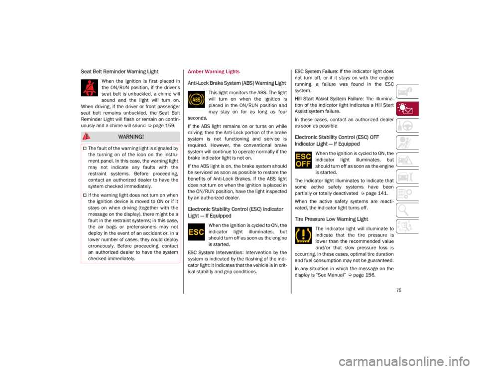
Seat Belt Reminder Warning Light
When the ignition is first placed in
the ON/RUN position, if the driver’s
seat belt is unbuckled, a chime will
sound and the light will turn on.
When driving, if the driver or front passenger
seat belt remains unbuckled, the Seat Belt
Reminder Light will flash or remain on contin -
uously and a chime will sound
Ú
page 159.
Amber Warning Lights
Anti-Lock Brake System (ABS) Warning Light
This light monitors the ABS. The light
will turn on when the ignition is
placed in the ON/RUN position and
may stay on for as long as four
seconds.
If the ABS light remains on or turns on while
driving, then the Anti-Lock portion of the brake
system is not functioning and service is
required. However, the conventional brake
system will continue to operate normally if the
brake indicator light is not on.
If the ABS light is on, the brake system should
be serviced as soon as possible to restore the
benefits of Anti-Lock Brakes. If the ABS light
does not turn on when the ignition is placed in
the ON/RUN position, have the light inspected
by an authorized dealer.
Electronic Stability Control (ESC) Indicator
Light — If Equipped
When the ignition is cycled to ON, the
indicator light illuminates, but
should turn off as soon as the engine
is started.
ESC System Intervention : Intervention by the
system is indicated by the flashing of the indi -
cator light: it indicates that the vehicle is in crit -
ical stability and grip conditions. ESC System Failure
: If the indicator light does
not turn off, or if it stays on with the engine
running, a failure was found in the ESC
system.
Hill Start Assist System Failure : The illumina-
tion of the indicator light indicates a Hill Start
Assist system failure.
In these cases, contact an authorized dealer
as soon as possible.
Electronic Stability Control (ESC) OFF
Indicator Light — If Equipped
When the ignition is cycled to ON, the
indicator light illuminates, but
should turn off as soon as the engine
is started.
The indicator light illuminates to indicate that
some active safety systems have been
partially or totally deactivated
Ú
page 141.
When the active safety systems are reacti -
vated, the indicator light turns off.
Tire Pressure Low Warning Light
The indicator light will illuminate to
indicate that the tire pressure is
lower than the recommended value
and/or that slow pressure loss is
occurring. In these cases, optimal tire duration
and fuel consumption may not be guaranteed.
In any situation in which the message on the
display is “See Manual”
Ú
page 156.
WARNING!
The fault of the warning light is signaled by
the turning on of the icon on the instru -
ment panel. In this case, the warning light
may not indicate any faults with the
restraint systems. Before proceeding,
contact an authorized dealer to have the
system checked immediately.
If the warning light does not turn on when
the ignition device is moved to ON or if it
stays on when driving (together with the
message on the display), there might be a
fault in the restraint systems; in this case,
the air bags or pretensioners may not
deploy in the event of an accident or, in a
lower number of cases, they could deploy
erroneously. Before proceeding, contact
an authorized dealer to have the system
checked immediately.
21_GA_OM_EN_USC_t.book Page 75
Page 78 of 284
GETTING TO KNOW YOUR INSTRUMENT PANEL
76
Tire Pressure Monitoring System (TPMS)
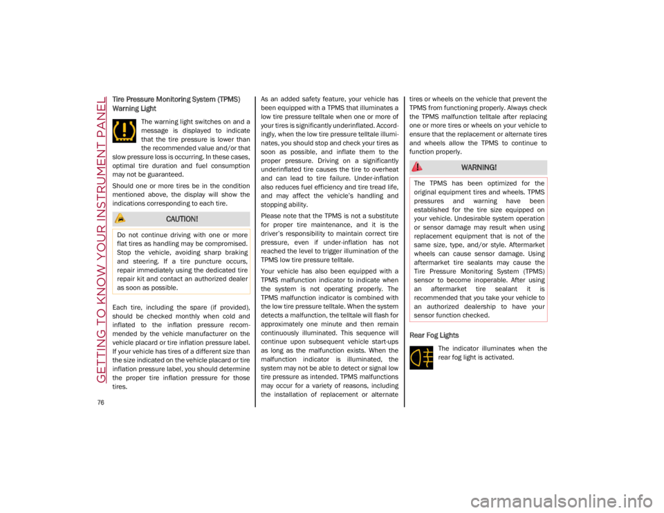
Warning Light
The warning light switches on and a
message is displayed to indicate
that the tire pressure is lower than
the recommended value and/or that
slow pressure loss is occurring. In these cases,
optimal tire duration and fuel consumption
may not be guaranteed.
Should one or more tires be in the condition
mentioned above, the display will show the
indications corresponding to each tire.
Each tire, including the spare (if provided),
should be checked monthly when cold and
inflated to the inflation pressure recom -
mended by the vehicle manufacturer on the
vehicle placard or tire inflation pressure label.
If your vehicle has tires of a different size than
the size indicated on the vehicle placard or tire
inflation pressure label, you should determine
the proper tire inflation pressure for those
tires. As an added safety feature, your vehicle has
been equipped with a TPMS that illuminates a
low tire pressure telltale when one or more of
your tires is significantly underinflated. Accord
-
ingly, when the low tire pressure telltale illumi -
nates, you should stop and check your tires as
soon as possible, and inflate them to the
proper pressure. Driving on a significantly
underinflated tire causes the tire to overheat
and can lead to tire failure. Under-inflation
also reduces fuel efficiency and tire tread life,
and may affect the vehicle’s handling and
stopping ability.
Please note that the TPMS is not a substitute
for proper tire maintenance, and it is the
driver’s responsibility to maintain correct tire
pressure, even if under-inflation has not
reached the level to trigger illumination of the
TPMS low tire pressure telltale.
Your vehicle has also been equipped with a
TPMS malfunction indicator to indicate when
the system is not operating properly. The
TPMS malfunction indicator is combined with
the low tire pressure telltale. When the system
detects a malfunction, the telltale will flash for
approximately one minute and then remain
continuously illuminated. This sequence will
continue upon subsequent vehicle start-ups
as long as the malfunction exists. When the
malfunction indicator is illuminated, the
system may not be able to detect or signal low
tire pressure as intended. TPMS malfunctions
may occur for a variety of reasons, including
the installation of replacement or alternate tires or wheels on the vehicle that prevent the
TPMS from functioning properly. Always check
the TPMS malfunction telltale after replacing
one or more tires or wheels on your vehicle to
ensure that the replacement or alternate tires
and wheels allow the TPMS to continue to
function properly.
Rear Fog Lights
The indicator illuminates when the
rear fog light is activated.
CAUTION!
Do not continue driving with one or more
flat tires as handling may be compromised.
Stop the vehicle, avoiding sharp braking
and steering. If a tire puncture occurs,
repair immediately using the dedicated tire
repair kit and contact an authorized dealer
as soon as possible.
WARNING!
The TPMS has been optimized for the
original equipment tires and wheels. TPMS
pressures and warning have been
established for the tire size equipped on
your vehicle. Undesirable system operation
or sensor damage may result when using
replacement equipment that is not of the
same size, type, and/or style. Aftermarket
wheels can cause sensor damage. Using
aftermarket tire sealants may cause the
Tire Pressure Monitoring System (TPMS)
sensor to become inoperable. After using
an aftermarket tire sealant it is
recommended that you take your vehicle to
an authorized dealership to have your
sensor function checked.
21_GA_OM_EN_USC_t.book Page 76
Page 81 of 284
79
Also check visually for any fluid leaks. Contact
an authorized dealer if the telltale comes on
when the engine is started again.
If the vehicle is used under demanding condi-
tions (e.g. in high-performance driving): slow
down and, if the warning light stays on, stop
the vehicle. Stop for two or three minutes with
the engine running and slightly accelerated to
facilitate better coolant circulation, then turn
the engine off. Check that the coolant level is
correct as described above.
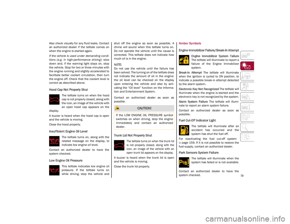
Hood Cap Not Properly Shut
The telltale turns on when the hood
cap is not properly closed, along with
the icon, an image of the vehicle with
an open hood cap appears on the
display.
A buzzer is heard when the hood cap is open
and the vehicle is moving.
Close the hood properly.
Insufficient Engine Oil Level
The telltale turns on, along with the
related message on the display, to
indicate low engine oil level.
Contact an authorized dealer to have the
system checked.
Low Engine Oil Pressure
This telltale indicates low engine oil
pressure. If the telltale turns on
while driving, stop the vehicle and shut off the engine as soon as possible. A
chime will sound when this telltale turns on.
Do not operate the vehicle until the cause is
corrected. This telltale does not indicate how
much oil is in the engine.
NOTE:
Do not use the vehicle until the failure has
been solved. The turning on of the telltale does
not indicate the amount of oil in the engine:
the oil level can be checked on the display
upon entering the vehicle and also by acti
-
vating the “Oil level” function on the Informa -
tion and Entertainment System.
Contact an authorized dealer as soon as
possible.
Trunk Lid Not Properly Shut
The telltale turns on when the trunk lid
is not properly closed, along with the
icon, an image of the vehicle with an
open trunk lid appears on the display.
A buzzer is heard when the trunk lid is open
and the vehicle is moving.
Close the trunk lid properly.
Amber Symbols
Engine Immobilizer Failure/Break-In Attempt
Engine Immobilizer System Failure
The telltale will illuminate to report a
failure of the Engine Immobilizer
system.
Break-In Attempt The telltale will illuminate
when the ignition is cycled to ON position, to
indicate a possible break-in attempt detected
by the alarm system.
Electronic Key Not Recognized The telltale will
illuminate when the engine is started and the
electronic key is not recognized by the system.
Alarm System Failure The telltale will illumi -
nate to report an alarm system failure.
Contact an authorized dealer as soon as
possible.
Fuel Cut-Off Indicator Light
The telltale will illuminate after an
accident has occurred and the
system has shut the fuel off.
For reactivating the fuel cut-off system
Ú
page 159. If it is not possible to restore the
fuel supply, contact an authorized dealer.
Park Sensors System Failure
The telltale will illuminate when the
system has failed or is not available.
Contact an authorized dealer to have the
system checked.
CAUTION!
If the LOW ENGINE OIL PRESSURE symbol
switches on when driving, stop the engine
immediately and contact an authorized
dealer.
21_GA_OM_EN_USC_t.book Page 79
Page 82 of 284
GETTING TO KNOW YOUR INSTRUMENT PANEL
80
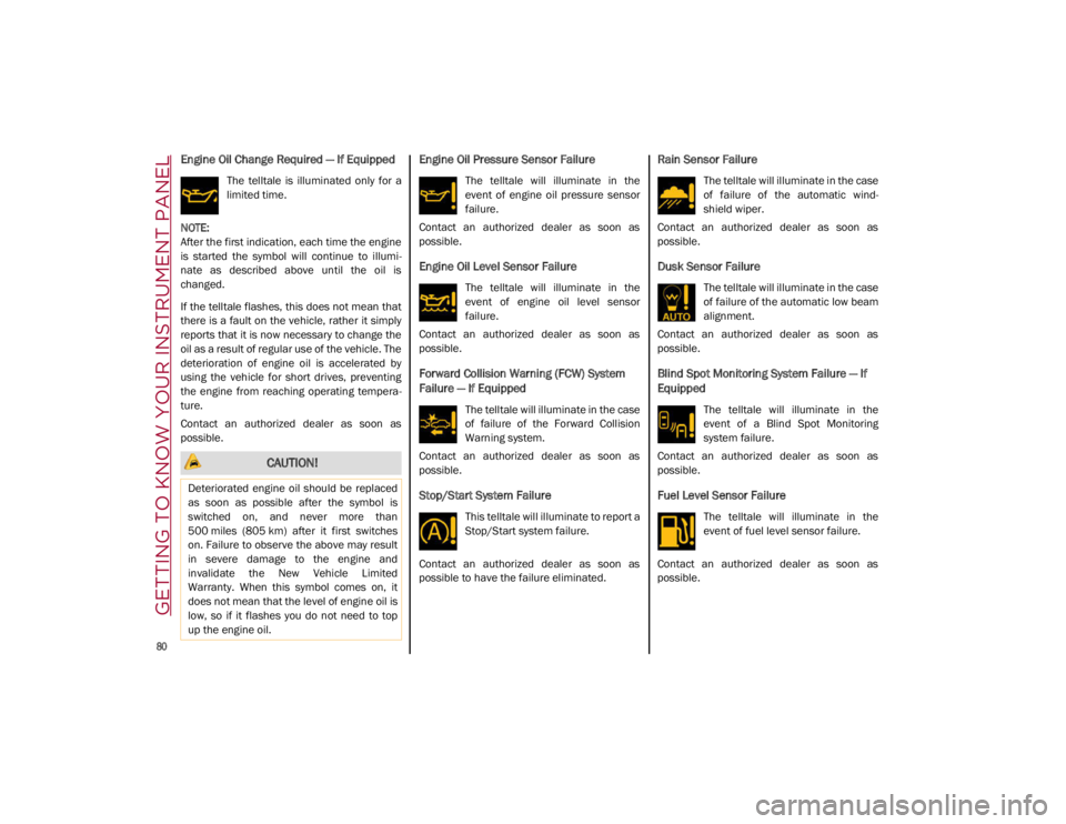
Engine Oil Change Required — If Equipped
The telltale is illuminated only for a
limited time.
NOTE:
After the first indication, each time the engine
is started the symbol will continue to illumi -
nate as described above until the oil is
changed.
If the telltale flashes, this does not mean that
there is a fault on the vehicle, rather it simply
reports that it is now necessary to change the
oil as a result of regular use of the vehicle. The
deterioration of engine oil is accelerated by
using the vehicle for short drives, preventing
the engine from reaching operating tempera -
ture.
Contact an authorized dealer as soon as
possible.
Engine Oil Pressure Sensor Failure
The telltale will illuminate in the
event of engine oil pressure sensor
failure.
Contact an authorized dealer as soon as
possible.
Engine Oil Level Sensor Failure
The telltale will illuminate in the
event of engine oil level sensor
failure.
Contact an authorized dealer as soon as
possible.
Forward Collision Warning (FCW) System
Failure — If Equipped
The telltale will illuminate in the case
of failure of the Forward Collision
Warning system.
Contact an authorized dealer as soon as
possible.
Stop/Start System Failure
This telltale will illuminate to report a
Stop/Start system failure.
Contact an authorized dealer as soon as
possible to have the failure eliminated.
Rain Sensor Failure
The telltale will illuminate in the case
of failure of the automatic wind -
shield wiper.
Contact an authorized dealer as soon as
possible.
Dusk Sensor Failure
The telltale will illuminate in the case
of failure of the automatic low beam
alignment.
Contact an authorized dealer as soon as
possible.
Blind Spot Monitoring System Failure — If
Equipped
The telltale will illuminate in the
event of a Blind Spot Monitoring
system failure.
Contact an authorized dealer as soon as
possible.
Fuel Level Sensor Failure
The telltale will illuminate in the
event of fuel level sensor failure.
Contact an authorized dealer as soon as
possible.
CAUTION!
Deteriorated engine oil should be replaced
as soon as possible after the symbol is
switched on, and never more than
500 miles (805 km) after it first switches
on. Failure to observe the above may result
in severe damage to the engine and
invalidate the New Vehicle Limited
Warranty. When this symbol comes on, it
does not mean that the level of engine oil is
low, so if it flashes you do not need to top
up the engine oil.
21_GA_OM_EN_USC_t.book Page 80
Page 139 of 284
137
Gross Vehicle Weight Rating (GVWR)
The GVWR is the total permissible weight of
your vehicle including driver, passengers,
vehicle, options and cargo. The label also
specifies maximum capacities of front and
rear axle systems (GAWR). Total load must be
limited so GVWR and front and rear GAWR are
not exceeded.
Payload
The payload of a vehicle is defined as the
allowable load weight a truck can carry,
including the weight of the driver, all passen-
gers, options and cargo.
Gross Axle Weight Rating (GAWR)
The GAWR is the maximum permissible load
on the front and rear axles. The load must be
distributed in the cargo area so that the GAWR
of each axle is not exceeded.
Each axle GAWR is determined by the compo -
nents in the system with the lowest load
carrying capacity (axle, springs, tires or
wheels). Heavier axles or suspension compo -
nents sometimes specified by purchasers for
increased durability do not necessarily
increase the vehicle's GVWR.
Tire Size
The tire size on the Vehicle Certification Label
represents the actual tire size on your vehicle.
Replacement tires must be equal to the load
capacity of this tire size.
Rim Size
This is the rim size that is appropriate for the
tire size listed.
Inflation Pressure
This is the cold tire inflation pressure for your
vehicle for all loading conditions up to full
GAWR.
Curb Weight
The curb weight of a vehicle is defined as the
total weight of the vehicle with all fluids,
including vehicle fuel, at full capacity condi -
tions, and with no occupants or cargo loaded
into the vehicle. The front and rear curb weight
values are determined by weighing your
vehicle on a commercial scale before any
occupants or cargo are added.
Loading
The actual total weight and the weight of the
front and rear of your vehicle at the ground can
best be determined by weighing it when it is
loaded and ready for operation. The entire vehicle should first be weighed on a
commercial scale to ensure that the GVWR
has not been exceeded. The weight on the
front and rear of the vehicle should then be
determined separately to be sure that the load
is properly distributed over the front and rear
axle. Weighing the vehicle may show that the
GAWR of either the front or rear axles has
been exceeded but the total load is within the
specified GVWR. If so, weight must be shifted
from front to rear or rear to front as appro
-
priate until the specified weight limitations are
met. Store the heavier items down low and be
sure that the weight is distributed equally.
Stow all loose items securely before driving.
Improper weight distributions can have an
adverse effect on the way your vehicle steers
and handles and the way the brakes operate.
CAUTION!
Do not load your vehicle any heavier than
the GVWR or the maximum front and rear
GAWR. If you do, parts on your vehicle can
break, or it can change the way your vehicle
handles. This could cause you to lose
control. Also overloading can shorten the
life of your vehicle.
21_GA_OM_EN_USC_t.book Page 137
Page 140 of 284

STARTING AND OPERATING
138
TRAILER TOWING
Trailer towing is not recommended for this
vehicle.
SUGGESTIONS FOR DRIVING
Saving Fuel
Below are some suggestions which may help
you save fuel and lower the amount of harmful
emissions released into the atmosphere.
Vehicle Maintenance
Checks and operations should be carried out
in accordance with the Maintenance Plan
Ú
page 204.
Tires
Check the tire pressures at least once every
four weeks: if the pressure is too low,
consumption levels increase as resistance to
rolling is higher.
Unnecessary Loads
Do not travel with an overloaded trunk. The
weight of the vehicle and its arrangement
greatly affect fuel consumption and stability.
Electric Devices
Use electrical systems only for the amount of
time needed. The rear window defroster, addi -
tional headlights, windshield wipers and
heater blower fan require a considerable
amount of energy; increasing the current
uptake increases fuel consumption (by up to
+25% when city driving). Climate Control System
Using the climate control system will increase
consumption: use standard ventilation when
the temperature outside permits.
Devices for Aerodynamic Control
The use of non-certified devices for aerody
-
namic control may adversely affect air drag
and consumption levels.
Driving Style
Starting
Do not warm up the engine at low or high revs
when the vehicle is stationary; this causes the
engine to warm up more slowly, thereby
increasing fuel consumption and emissions. It
is therefore advisable to drive off immediately,
slowly, avoiding high speeds: by doing this the
engine will warm up more quickly.
Unnecessary Actions
Avoid revving up when starting at traffic lights
or before stopping the engine. This action is
unnecessary and causes increased fuel
consumption and pollution.
Gear Selection
Use a high gear when traffic and road condi -
tions allow it. Using a low gear for faster accel -
eration will increase fuel consumption.
Improper use of a high gear increases
consumption, emissions and engine wear. Max. Speed
Fuel consumption considerably increases as
speed increases. Maintain a constant speed,
avoiding unnecessary braking and accelera
-
tion, which cost in terms of both fuel consump -
tion and emissions.
Acceleration
Accelerating violently severely affects consump -
tion and emissions: acceleration should be
gradual and should not exceed the maximum
torque.
Conditions Of Use
Cold Starting
Short trips and frequent cold starts will not
allow the engine to reach optimum operating
temperature. This results in a significant
increase in consumption levels (from +15 to
+30% in city driving) and emissions.
Traffic And Road Conditions
High fuel consumption is caused by heavy
traffic, for instance when traveling in traffic
with frequent use of low gears or in cities with
many traffic lights. Winding mountain roads
and rough road surfaces also adversely affect
consumption.
Stops In Traffic
During prolonged stops (e.g. railway cross -
ings), turn off the engine.
21_GA_OM_EN_USC_t.book Page 138
Page 160 of 284

SAFETY
158
TPMS Temporarily Disabled:
TPMS Check Message
When a system fault is detected, the Tire Pres-
sure Monitoring System Warning Light will
flash on and off for 75 seconds, and then
remain on solid. The system fault will also
sound a chime. If the ignition is cycled, this
sequence will repeat, provided that the system
fault still exists. The Tire Pressure Monitoring
System Warning Light will turn off when the
fault condition no longer exists. A system fault
can occur due to any of the following:
Jamming due to electronic devices or
driving next to facilities emitting the same
radio frequencies as the TPMS sensors.
Installing some form of aftermarket window
tinting that affects radio wave signals.
Packed snow or ice around the wheels or
wheel housings.
Using tire chains on the vehicle.
Using wheels/tires not equipped with TPMS
sensors.
After the punctured tire has been repaired
with the original tire sealant contained in the
Tire Kit, the previous condition must be
restored so that the Warning Light is off
during normal driving. TPMS Deactivation
The TPMS can be deactivated by replacing all
four wheel and tire assemblies (road tires)
with wheel and tire assemblies that do not
have TPMS sensors, such as when installing
winter wheel and tire assemblies on your
vehicle.
To deactivate the TPMS, first replace all four
wheel and tire assemblies (road tires) with
tires not equipped with Tire Pressure Moni
-
toring System sensors. Then, drive the vehicle
for 20 minutes above 15 mph (24 km/h). The
TPMS will chime, the TPMS Warning Light will
flash on and off for 75 seconds and then
remain on. The instrument cluster will display
the “SERVICE TPM SYSTEM” message and
then display dashes (--) in place of the pres -
sure values.
Beginning with the next ignition switch cycle,
the TPMS will no longer chime or display the
“SERVICE TPM SYSTEM” message in the
instrument cluster. Instead, dashes (--) will
remain in place of the pressure values.
To reactivate the TPMS, replace all four wheel
and tire assemblies (road tires) with tires
equipped with TPMS sensors. Then, drive the
vehicle for up to 20 minutes above 15 mph
(24 km/h). The TPMS will chime, the TPMS
Warning Light will flash on and off for 75
seconds and then turn off. The instrument cluster will display the “SERVICE TPM
SYSTEM” message and then display pressure
values in place of the dashes. On the next igni
-
tion switch cycle the "SERVICE TPM SYSTEM"
message will no longer be displayed, as long
as no system fault exists.
NOTE:
The TPMS is not intended to replace normal
tire care and maintenance, or to provide
warning of a tire failure or condition.
The TPMS should not be used as a tire pres -
sure gauge while adjusting your tire pressure.
Driving on a significantly underinflated tire will
cause the tire to overheat, and can lead to tire
failure. Underinflation also reduces fuel effi -
ciency and tire tread life, and may affect the
vehicle’s handling and stopping ability.
The TPMS is not a substitute for proper tire
maintenance, and it is the driver’s responsi -
bility to maintain correct tire pressure using
an accurate tire pressure gauge, even if
underinflation has not reached the level to
trigger illumination of the Tire Pressure
Monitoring System Warning Light.
Seasonal temperature changes will affect
tire pressure, and the TPMS will monitor the
actual tire pressure in the tire
Ú
page 273.
21_GA_OM_EN_USC_t.book Page 158