rear entertainment ALFA ROMEO GIULIA 2021 Owners Manual
[x] Cancel search | Manufacturer: ALFA ROMEO, Model Year: 2021, Model line: GIULIA, Model: ALFA ROMEO GIULIA 2021Pages: 284, PDF Size: 8.87 MB
Page 28 of 284
GETTING TO KNOW YOUR VEHICLE
26
Automatic Door Locks — If Equipped
The auto door lock feature default condition is
enabled. When enabled, the door locks will
lock automatically when the vehicle's speed
exceeds 12 mph (20 km/h). The auto door
lock feature is enabled/disabled through the
radio screen. Refer to the Information and
Entertainment System Owner’s Manual
Supplement for further information.
Child-Protection Door Lock System — Rear
Doors
To provide a safer environment for small chil-
dren riding in the rear seats, the rear doors are
equipped with a Child-Protection Door Lock
system.
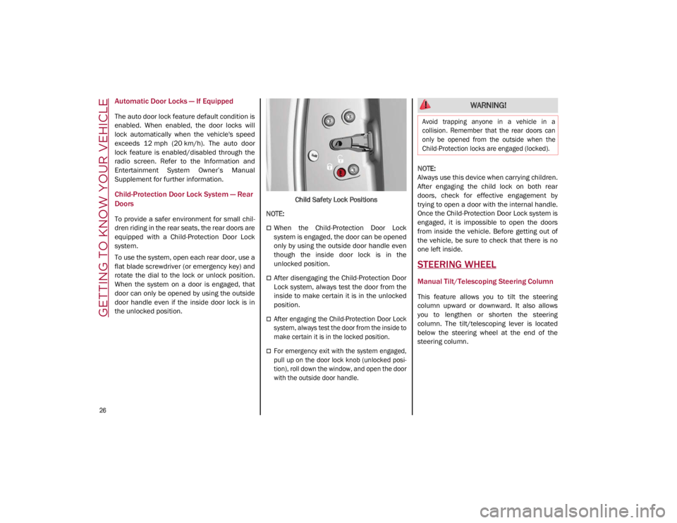
To use the system, open each rear door, use a
flat blade screwdriver (or emergency key) and
rotate the dial to the lock or unlock position.
When the system on a door is engaged, that
door can only be opened by using the outside
door handle even if the inside door lock is in
the unlocked position. Child Safety Lock Positions
NOTE:
When the Child-Protection Door Lock
system is engaged, the door can be opened
only by using the outside door handle even
though the inside door lock is in the
unlocked position.
After disengaging the Child-Protection Door
Lock system, always test the door from the
inside to make certain it is in the unlocked
position.
After engaging the Child-Protection Door Lock
system, always test the door from the inside to
make certain it is in the locked position.
For emergency exit with the system engaged,
pull up on the door lock knob (unlocked posi -
tion), roll down the window, and open the door
with the outside door handle.
NOTE:
Always use this device when carrying children.
After engaging the child lock on both rear
doors, check for effective engagement by
trying to open a door with the internal handle.
Once the Child-Protection Door Lock system is
engaged, it is impossible to open the doors
from inside the vehicle. Before getting out of
the vehicle, be sure to check that there is no
one left inside.
STEERING WHEEL
Manual Tilt/Telescoping Steering Column
This feature allows you to tilt the steering
column upward or downward. It also allows
you to lengthen or shorten the steering
column. The tilt/telescoping lever is located
below the steering wheel at the end of the
steering column.
WARNING!
Avoid trapping anyone in a vehicle in a
collision. Remember that the rear doors can
only be opened from the outside when the
Child-Protection locks are engaged (locked).
21_GA_OM_EN_USC_t.book Page 26
Page 35 of 284
33
Power Lumbar
The power lumbar switch is located on the
outboard side of the power seat. Push the
switch forward or rearward to increase or
decrease the lumbar support. Push the switch
upward or downward to raise or lower the
lumbar support.
Seat Cushion Extension — If Equipped
Lift the adjustment lever and push the front of
the cushion forward or rearward to extend the
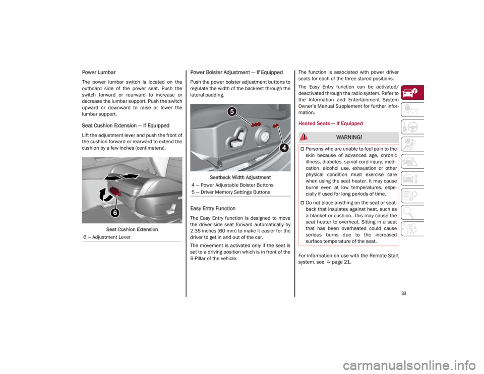
cushion by a few inches (centimeters).Seat Cushion Extension
Power Bolster Adjustment — If Equipped
Push the power bolster adjustment buttons to
regulate the width of the backrest through the
lateral padding.
Seatback Width Adjustment
Easy Entry Function
The Easy Entry function is designed to move
the driver side seat forward automatically by
2.36 inches (60 mm) to make it easier for the
driver to get in and out of the car.
The movement is activated only if the seat is
set to a driving position which is in front of the
B-Pillar of the vehicle. The function is associated with power driver
seats for each of the three stored positions.
The Easy Entry function can be activated/
deactivated through the radio system. Refer to
the Information and Entertainment System
Owner’s Manual Supplement for further infor
-
mation.
Heated Seats — If Equipped
For information on use with the Remote Start
system, see
Ú
page 21.
6 — Adjustment Lever
4 — Power Adjustable Bolster Buttons
5 — Driver Memory Settings Buttons
WARNING!
Persons who are unable to feel pain to the
skin because of advanced age, chronic
illness, diabetes, spinal cord injury, medi
-
cation, alcohol use, exhaustion or other
physical condition must exercise care
when using the seat heater. It may cause
burns even at low temperatures, espe -
cially if used for long periods of time.
Do not place anything on the seat or seat -
back that insulates against heat, such as
a blanket or cushion. This may cause the
seat heater to overheat. Sitting in a seat
that has been overheated could cause
serious burns due to the increased
surface temperature of the seat.
21_GA_OM_EN_USC_t.book Page 33
Page 36 of 284
GETTING TO KNOW YOUR VEHICLE
34
Front Heated Seats — If Equipped
NOTE:
Quadrifoglio vehicles equipped with Sparco
Racing Seats will not be equipped with the
heated seat feature.
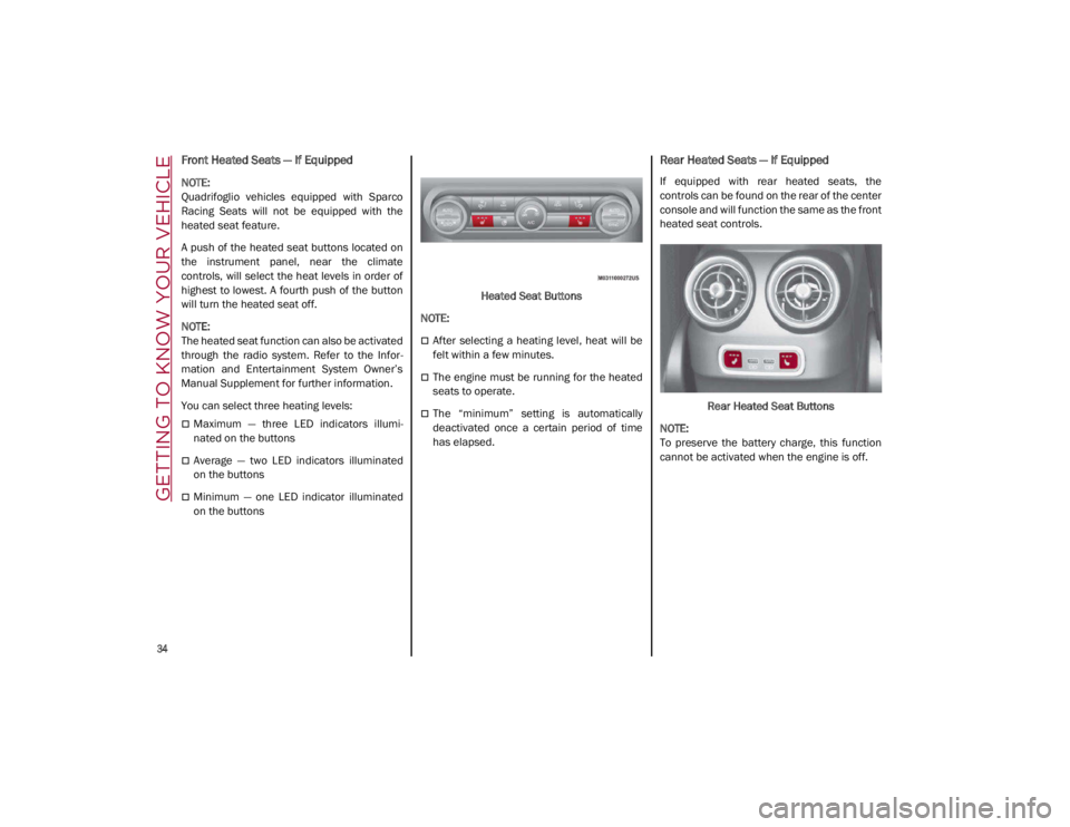
A push of the heated seat buttons located on
the instrument panel, near the climate
controls, will select the heat levels in order of
highest to lowest. A fourth push of the button
will turn the heated seat off.
NOTE:
The heated seat function can also be activated
through the radio system. Refer to the Infor-
mation and Entertainment System Owner’s
Manual Supplement for further information.
You can select three heating levels:
Maximum — three LED indicators illumi -
nated on the buttons
Average — two LED indicators illuminated
on the buttons
Minimum — one LED indicator illuminated
on the buttons Heated Seat Buttons
NOTE:
After selecting a heating level, heat will be
felt within a few minutes.
The engine must be running for the heated
seats to operate.
The “minimum” setting is automatically
deactivated once a certain period of time
has elapsed.
Rear Heated Seats — If Equipped
If equipped with rear heated seats, the
controls can be found on the rear of the center
console and will function the same as the front
heated seat controls.
Rear Heated Seat Buttons
NOTE:
To preserve the battery charge, this function
cannot be activated when the engine is off.
21_GA_OM_EN_USC_t.book Page 34
Page 60 of 284
GETTING TO KNOW YOUR VEHICLE
58
NOTE:
Do not place the key fob or any other type of
metal/magnetized object inside the mobile
phone housing or near the wireless
charging pad.
Be sure to place the mobile device correctly
(display facing upward) on the wireless
charging pad.
The ignition must be in the ON/RUN position
in order for the phone to charge.
To avoid interference with the key fob
search, the wireless charging pad will stop
charging when any door is opened.The following messages will display in the
radio system:
“Your Phone Is Being Charged” — The phone
has begun to charge.
“Phone Fully Charged” — The phone has
completed charging its battery.
“Foreign Object Detected” — The phone is
not enabled for wireless charging or an
object that is not permitted has been placed
on the wireless charging pad.
“Unavailable System” — There is a malfunc
-
tion with the wireless charging pad.
The driver can deactivate these messages
through the radio system. Refer to the Infor -
mation and Entertainment System Owner’s
Manual Supplement for further information.
POWER WINDOWS
Power Window Controls
The power window switches work with the igni -
tion in the ACC or ON/RUN position and for
three minutes after the ignition has been
placed in the OFF position. When one of the
front doors is opened, this operation is
disabled.
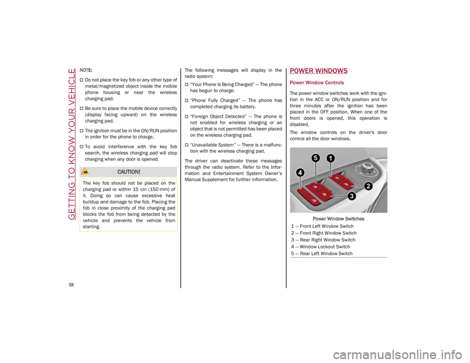
The window controls on the driver's door
control all the door windows.
Power Window Switches
CAUTION!
The key fob should not be placed on the
charging pad or within 15 cm (150 mm) of
it. Doing so can cause excessive heat
buildup and damage to the fob. Placing the
fob in close proximity of the charging pad
blocks the fob from being detected by the
vehicle and prevents the vehicle from
starting.
1 — Front Left Window Switch
2 — Front Right Window Switch
3 — Rear Right Window Switch
4 — Window Lockout Switch
5 — Rear Left Window Switch
21_GA_OM_EN_USC_t.book Page 58
Page 92 of 284
STARTING AND OPERATING
90
100 to 300 miles (160 to 483 km):
Press the accelerator pedal slowly and not
more than halfway to avoid rapid accelera-
tion in lower gears (FIRST to THIRD gears).
Avoid aggressive braking.
Drive with the engine speed less than
5,000 RPM.
Maintain vehicle speed below 70 mph
(112 km/h) and observe local speed limits.
300 to 500 miles (483 to 805 km):
Exercise the full engine RPM range, shifting
manually (paddles or gear shift) at higher
RPM when possible.
Do not perform sustained operation with
the accelerator pedal at wide open throttle.
Maintain vehicle speed below 85 mph
(136 km/h) and observe local speed limits.
For the first 1,500 miles (2,414 km):
Do not participate in track events, sport
driving schools, or similar activities during
the first 1,500 miles (2,414 km).
NOTE:
Monitor engine oil with every refueling and add
if necessary. Oil and fuel consumption may be
higher through the first oil change interval.
ELECTRIC PARK BRAKE (EPB)
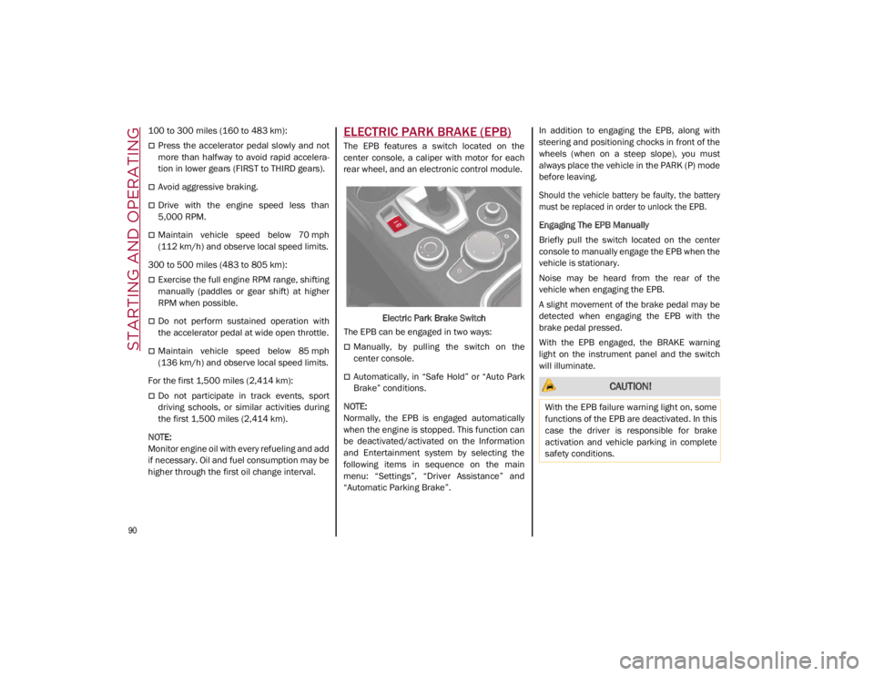
The EPB features a switch located on the
center console, a caliper with motor for each
rear wheel, and an electronic control module.
Electric Park Brake Switch
The EPB can be engaged in two ways:
Manually, by pulling the switch on the
center console.
Automatically, in “Safe Hold” or “Auto Park
Brake” conditions.
NOTE:
Normally, the EPB is engaged automatically
when the engine is stopped. This function can
be deactivated/activated on the Information
and Entertainment system by selecting the
following items in sequence on the main
menu: “Settings”, “Driver Assistance” and
“Automatic Parking Brake”. In addition to engaging the EPB, along with
steering and positioning chocks in front of the
wheels (when on a steep slope), you must
always place the vehicle in the PARK (P) mode
before leaving.
Should the vehicle battery be faulty, the battery
must be replaced in order to unlock the EPB.
Engaging The EPB Manually
Briefly pull the switch located on the center
console to manually engage the EPB when the
vehicle is stationary.
Noise may be heard from the rear of the
vehicle when engaging the EPB.
A slight movement of the brake pedal may be
detected when engaging the EPB with the
brake pedal pressed.
With the EPB engaged, the BRAKE warning
light on the instrument panel and the switch
will illuminate. CAUTION!
With the EPB failure warning light on, some
functions of the EPB are deactivated. In this
case the driver is responsible for brake
activation and vehicle parking in complete
safety conditions.
21_GA_OM_EN_USC_t.book Page 90
Page 152 of 284

SAFETY
150
Rear Cross Path Detection (RCP) System
The Rear Cross Path Detection (RCP) system
assists the driver during reverse maneuvers in
the case of reduced visibility.
When the ABSA system is active, the RCP
system monitors the rear detection areas on
both sides of the vehicle to detect objects
moving towards the sides of the vehicle at a
minimum speed between 0.6 mph and 2 mph
(1 km/h and 3km/h) to objects moving at a
maximum speed of 22 mph (35 km/h).
These are generally occurrences that happen
in parking areas.
The system activation is signaled to the driver
by means of a visual and audible warning.
NOTE:
If the sensors are covered by objects or vehi-
cles, the system may not work as intended.
Changing the system sensitivity
To change the sensitivity and the strength of
the torque intervention on the steering wheel,
refer to the Information and Entertainment
System Owner’s Manual Supplement.Driver Attention Assist (DAA) System — If
Equipped
The Driver Attention Assist (DAA) system
detects when the driver is feeling fatigued and
warns the driver to pull over and take a break.
To Activate/Deactivate
The DAA system can be activated and deacti -
vated through the radio system by selecting
the following in order:
1. “Driver Assistance”
2. “Driver Attention Assist”
System Intervention
Using information from the front camera, the
system implements two operating logics:
The first operating logic takes the driving style
into account, observing the road and
detecting to what extent the driver can
continue driving with few lane crossing events.
The second operating logic measures the time
spent behind the wheel with the vehicle speed
above 40 mph (60 km/h) and below 110 mph
(180 km/h). If the “Standard” option is
selected, in these conditions, the “Dozy
Driver” message may appear after three hours
of driving. If the “Early” option is selected and
these conditions occur, the “Dozy Driver”
message will be displayed after two hours of
driving.
NOTE:
If the conditions described above are not
detected continuously during the entire driving
period, the “Dozy Driver” message may be
displayed later than two or three hours. If the
driving style indicates that the driver is unable
to follow the road trajectory and respect the
horizontal lane markings, the red symbol will
appear on the instrument cluster display to
suggest that the driver should stop for a break.
An audible signal will also sound.
If the driver accepts the suggestion provided
by the system by pushing the MENU button on
the multifunction lever, the message will
disappear from the display and the symbol will
be displayed in the dedicated area of the
instrument cluster display until the next
engine shutdown.
If the driver ignores the warning provided by
the system and does not stop, the message
will continue to remain on the display, along
with the symbol.
WARNING!
The DAA System is an aid for driving and does
not relieve the driver of the responsibility of
driving the vehicle. If you experience fatigue
while driving, pull over safely for a break
without waiting for the DAA to intervene. Only
return to the road when you are in the right
physical and mental condition to prevent
endangering yourself and other drivers.
21_GA_OM_EN_USC_t.book Page 150
Page 228 of 284
SERVICING AND MAINTENANCE
226
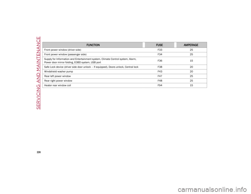
FUNCTIONFUSEAMPERAGE
Front power window (driver side)F3325
Front power window (passenger side) F3425
Supply for Information and Entertainment system, Climate Control system, Alarm,
Power door mirror folding, EOBD system, USB port F36
15
Safe Lock device (driver side door unlock – if equipped), Doors unlock, Central lock F3820
Windshield washer pump F4320
Rear left power window F4725
Rear right power window F4825
Heater rear window coil F9415
21_GA_OM_EN_USC_t.book Page 226