tire pressure ALFA ROMEO GIULIA 2021 Owners Manual
[x] Cancel search | Manufacturer: ALFA ROMEO, Model Year: 2021, Model line: GIULIA, Model: ALFA ROMEO GIULIA 2021Pages: 284, PDF Size: 8.87 MB
Page 13 of 284

11
SAFETY
ACTIVE SAFETY SYSTEMS ..................... 141
Anti-Lock Brake System (ABS) ........... 141
Active Torque Vectoring (ATV) —
If Equipped ...........................................142 Dynamic Steering Torque (DST) .........142
Drive Train Control (DTC) System —
If Equipped ...........................................142 Electronic Stability Control (ESC) ........142
Hill Start Assist (HSA)...........................143
Panic Brake Assist (PBA) .....................143
Traction Control System (TCS) ............144
AUXILIARY DRIVING SYSTEMS .............. 144
Blind Spot Monitoring (BSM) System —
If Equipped ..........................................145 Active Blind Spot Assist (ABSA) System —
If Equipped ..........................................147 Driver Attention Assist (DAA) System —
If Equipped ...........................................150 Forward Collision Warning (FCW)
System ..................................................151 Tire Pressure Monitoring
System (TPMS) ..................................... 156
OCCUPANT RESTRAINT SYSTEMS ....... 159
Occupant Restraint Systems
Features ..............................................159 Important Safety Precautions .............159
Seat Belt Systems ............................... 159
Supplemental Restraint
Systems (SRS)...................................... 165 Child Restraints....................................174
SAFETY TIPS .......................................... 187
Transporting Passengers .................... 187
Transporting Pets ............................... 187
Safety Checks You Should Make
Inside The Vehicle .............................. 187 Periodic Safety Checks You Should
Make Outside The Vehicle .................. 188 Exhaust Gas ......................................... 189
Carbon Monoxide Warnings................ 189
IN CASE OF EMERGENCY
HAZARD WARNING FLASHERS ............. 190SOS - EMERGENCY CALL ...................... 190
TIRE SERVICE KIT .................................. 194
Description ........................................... 194
Inflation Procedure .............................. 195
Checking And Restoring Tire
Pressure ............................................... 197 Sealant Cartridge Replacement ......... 197
JUMP STARTING .................................... 198
Remote Battery Connection Posts ..... 198
Jump Starting....................................... 199
Bump Starting...................................... 200
IF YOUR ENGINE OVERHEATS ............... 200
MANUAL PARK RELEASE ....................... 201
TOWING A DISABLED VEHICLE ............. 201
Rear Wheel Drive (RWD) Models........ 202
All Wheel Drive (AWD) Models ............ 202
TOW EYES............................................... 202ENHANCED ACCIDENT
RESPONSE SYSTEM (EARS) .................. 203EVENT DATA RECORDER (EDR) ............ 203 SERVICING AND MAINTENANCE
SCHEDULED SERVICING ....................... 204
Periodic Checks................................... 204
Heavy Usage Of The Vehicle............... 204
Maintenance Plan — 2.0L Engine ...... 205
Maintenance Plan — 2.9L Engine ...... 208
ENGINE COMPARTMENT....................... 211
Checking Levels — 2.0L Engine ......... 211
Checking Levels — 2.9L Engine ........ 212
Engine Oil............................................. 213
Engine Coolant .................................... 214
Washer Fluid For Windshield/
Headlights............................................ 214 Brake Fluid .......................................... 214
Automatic Transmission Activation
System Oil ............................................ 214 Useful Advice For Extending
The Life Of Your Battery ...................... 214 Battery ................................................. 215
Pressure Washing ............................... 215
BATTERY RECHARGING......................... 215
Important Notes .................................. 215
VEHICLE MAINTENANCE ....................... 217
Engine Oil............................................. 217
Engine Oil Filter ................................... 217
Engine Air Cleaner............................... 217
Air Conditioning System
Maintenance ....................................... 217 Lubricating Moving Parts Of
The Bodywork ...................................... 218 Windshield Wiper ................................ 218
21_GA_OM_EN_USC_t.book Page 11
Page 15 of 284
13
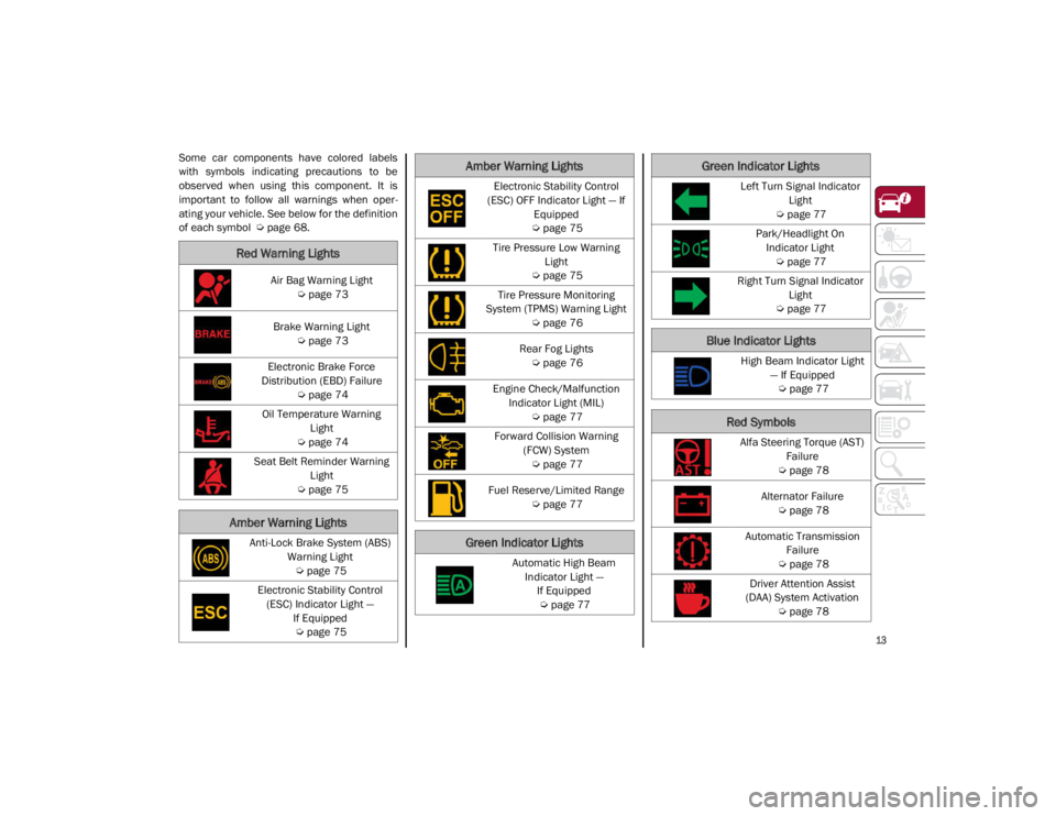
Some car components have colored labels
with symbols indicating precautions to be
observed when using this component. It is
important to follow all warnings when oper-
ating your vehicle. See below for the definition
of each symbol
Ú
page 68.
Red Warning Lights
Air Bag Warning Light
Ú
page 73
Brake Warning Light
Ú
page 73
Electronic Brake Force
Distribution (EBD) Failure
Ú
page 74
Oil Temperature Warning Light
Ú
page 74
Seat Belt Reminder Warning Light
Ú
page 75
Amber Warning Lights
Anti-Lock Brake System (ABS)
Warning Light
Ú
page 75
Electronic Stability Control (ESC) Indicator Light — If Equipped
Ú
page 75
Electronic Stability Control
(ESC) OFF Indicator Light — If Equipped
Ú
page 75
Tire Pressure Low Warning Light
Ú
page 75
Tire Pressure Monitoring
System (TPMS) Warning Light
Ú
page 76
Rear Fog Lights
Ú
page 76
Engine Check/Malfunction Indicator Light (MIL)
Ú
page 77
Forward Collision Warning (FCW) System
Ú
page 77
Fuel Reserve/Limited Range
Ú
page 77
Green Indicator Lights
Automatic High Beam
Indicator Light — If Equipped
Ú
page 77
Amber Warning Lights
Left Turn Signal Indicator
Light
Ú
page 77
Park/Headlight On Indicator Light
Ú
page 77
Right Turn Signal Indicator Light
Ú
page 77
Blue Indicator Lights
High Beam Indicator Light
— If Equipped
Ú
page 77
Red Symbols
Alfa Steering Torque (AST)
Failure
Ú
page 78
Alternator Failure
Ú
page 78
Automatic Transmission Failure
Ú
page 78
Driver Attention Assist
(DAA) System Activation
Ú
page 78
Green Indicator Lights
21_GA_OM_EN_USC_t.book Page 13
Page 77 of 284
75
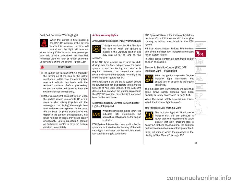
Seat Belt Reminder Warning Light
When the ignition is first placed in
the ON/RUN position, if the driver’s
seat belt is unbuckled, a chime will
sound and the light will turn on.
When driving, if the driver or front passenger
seat belt remains unbuckled, the Seat Belt
Reminder Light will flash or remain on contin -
uously and a chime will sound
Ú
page 159.
Amber Warning Lights
Anti-Lock Brake System (ABS) Warning Light
This light monitors the ABS. The light
will turn on when the ignition is
placed in the ON/RUN position and
may stay on for as long as four
seconds.
If the ABS light remains on or turns on while
driving, then the Anti-Lock portion of the brake
system is not functioning and service is
required. However, the conventional brake
system will continue to operate normally if the
brake indicator light is not on.
If the ABS light is on, the brake system should
be serviced as soon as possible to restore the
benefits of Anti-Lock Brakes. If the ABS light
does not turn on when the ignition is placed in
the ON/RUN position, have the light inspected
by an authorized dealer.
Electronic Stability Control (ESC) Indicator
Light — If Equipped
When the ignition is cycled to ON, the
indicator light illuminates, but
should turn off as soon as the engine
is started.
ESC System Intervention : Intervention by the
system is indicated by the flashing of the indi -
cator light: it indicates that the vehicle is in crit -
ical stability and grip conditions. ESC System Failure
: If the indicator light does
not turn off, or if it stays on with the engine
running, a failure was found in the ESC
system.
Hill Start Assist System Failure : The illumina-
tion of the indicator light indicates a Hill Start
Assist system failure.
In these cases, contact an authorized dealer
as soon as possible.
Electronic Stability Control (ESC) OFF
Indicator Light — If Equipped
When the ignition is cycled to ON, the
indicator light illuminates, but
should turn off as soon as the engine
is started.
The indicator light illuminates to indicate that
some active safety systems have been
partially or totally deactivated
Ú
page 141.
When the active safety systems are reacti -
vated, the indicator light turns off.
Tire Pressure Low Warning Light
The indicator light will illuminate to
indicate that the tire pressure is
lower than the recommended value
and/or that slow pressure loss is
occurring. In these cases, optimal tire duration
and fuel consumption may not be guaranteed.
In any situation in which the message on the
display is “See Manual”
Ú
page 156.
WARNING!
The fault of the warning light is signaled by
the turning on of the icon on the instru -
ment panel. In this case, the warning light
may not indicate any faults with the
restraint systems. Before proceeding,
contact an authorized dealer to have the
system checked immediately.
If the warning light does not turn on when
the ignition device is moved to ON or if it
stays on when driving (together with the
message on the display), there might be a
fault in the restraint systems; in this case,
the air bags or pretensioners may not
deploy in the event of an accident or, in a
lower number of cases, they could deploy
erroneously. Before proceeding, contact
an authorized dealer to have the system
checked immediately.
21_GA_OM_EN_USC_t.book Page 75
Page 78 of 284
GETTING TO KNOW YOUR INSTRUMENT PANEL
76
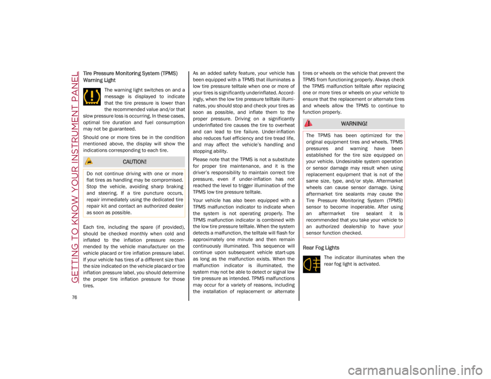
Tire Pressure Monitoring System (TPMS)
Warning Light
The warning light switches on and a
message is displayed to indicate
that the tire pressure is lower than
the recommended value and/or that
slow pressure loss is occurring. In these cases,
optimal tire duration and fuel consumption
may not be guaranteed.
Should one or more tires be in the condition
mentioned above, the display will show the
indications corresponding to each tire.
Each tire, including the spare (if provided),
should be checked monthly when cold and
inflated to the inflation pressure recom -
mended by the vehicle manufacturer on the
vehicle placard or tire inflation pressure label.
If your vehicle has tires of a different size than
the size indicated on the vehicle placard or tire
inflation pressure label, you should determine
the proper tire inflation pressure for those
tires. As an added safety feature, your vehicle has
been equipped with a TPMS that illuminates a
low tire pressure telltale when one or more of
your tires is significantly underinflated. Accord
-
ingly, when the low tire pressure telltale illumi -
nates, you should stop and check your tires as
soon as possible, and inflate them to the
proper pressure. Driving on a significantly
underinflated tire causes the tire to overheat
and can lead to tire failure. Under-inflation
also reduces fuel efficiency and tire tread life,
and may affect the vehicle’s handling and
stopping ability.
Please note that the TPMS is not a substitute
for proper tire maintenance, and it is the
driver’s responsibility to maintain correct tire
pressure, even if under-inflation has not
reached the level to trigger illumination of the
TPMS low tire pressure telltale.
Your vehicle has also been equipped with a
TPMS malfunction indicator to indicate when
the system is not operating properly. The
TPMS malfunction indicator is combined with
the low tire pressure telltale. When the system
detects a malfunction, the telltale will flash for
approximately one minute and then remain
continuously illuminated. This sequence will
continue upon subsequent vehicle start-ups
as long as the malfunction exists. When the
malfunction indicator is illuminated, the
system may not be able to detect or signal low
tire pressure as intended. TPMS malfunctions
may occur for a variety of reasons, including
the installation of replacement or alternate tires or wheels on the vehicle that prevent the
TPMS from functioning properly. Always check
the TPMS malfunction telltale after replacing
one or more tires or wheels on your vehicle to
ensure that the replacement or alternate tires
and wheels allow the TPMS to continue to
function properly.
Rear Fog Lights
The indicator illuminates when the
rear fog light is activated.
CAUTION!
Do not continue driving with one or more
flat tires as handling may be compromised.
Stop the vehicle, avoiding sharp braking
and steering. If a tire puncture occurs,
repair immediately using the dedicated tire
repair kit and contact an authorized dealer
as soon as possible.
WARNING!
The TPMS has been optimized for the
original equipment tires and wheels. TPMS
pressures and warning have been
established for the tire size equipped on
your vehicle. Undesirable system operation
or sensor damage may result when using
replacement equipment that is not of the
same size, type, and/or style. Aftermarket
wheels can cause sensor damage. Using
aftermarket tire sealants may cause the
Tire Pressure Monitoring System (TPMS)
sensor to become inoperable. After using
an aftermarket tire sealant it is
recommended that you take your vehicle to
an authorized dealership to have your
sensor function checked.
21_GA_OM_EN_USC_t.book Page 76
Page 139 of 284
137
Gross Vehicle Weight Rating (GVWR)
The GVWR is the total permissible weight of
your vehicle including driver, passengers,
vehicle, options and cargo. The label also
specifies maximum capacities of front and
rear axle systems (GAWR). Total load must be
limited so GVWR and front and rear GAWR are
not exceeded.
Payload
The payload of a vehicle is defined as the
allowable load weight a truck can carry,
including the weight of the driver, all passen-
gers, options and cargo.
Gross Axle Weight Rating (GAWR)
The GAWR is the maximum permissible load
on the front and rear axles. The load must be
distributed in the cargo area so that the GAWR
of each axle is not exceeded.
Each axle GAWR is determined by the compo -
nents in the system with the lowest load
carrying capacity (axle, springs, tires or
wheels). Heavier axles or suspension compo -
nents sometimes specified by purchasers for
increased durability do not necessarily
increase the vehicle's GVWR.
Tire Size
The tire size on the Vehicle Certification Label
represents the actual tire size on your vehicle.
Replacement tires must be equal to the load
capacity of this tire size.
Rim Size
This is the rim size that is appropriate for the
tire size listed.
Inflation Pressure
This is the cold tire inflation pressure for your
vehicle for all loading conditions up to full
GAWR.
Curb Weight
The curb weight of a vehicle is defined as the
total weight of the vehicle with all fluids,
including vehicle fuel, at full capacity condi -
tions, and with no occupants or cargo loaded
into the vehicle. The front and rear curb weight
values are determined by weighing your
vehicle on a commercial scale before any
occupants or cargo are added.
Loading
The actual total weight and the weight of the
front and rear of your vehicle at the ground can
best be determined by weighing it when it is
loaded and ready for operation. The entire vehicle should first be weighed on a
commercial scale to ensure that the GVWR
has not been exceeded. The weight on the
front and rear of the vehicle should then be
determined separately to be sure that the load
is properly distributed over the front and rear
axle. Weighing the vehicle may show that the
GAWR of either the front or rear axles has
been exceeded but the total load is within the
specified GVWR. If so, weight must be shifted
from front to rear or rear to front as appro
-
priate until the specified weight limitations are
met. Store the heavier items down low and be
sure that the weight is distributed equally.
Stow all loose items securely before driving.
Improper weight distributions can have an
adverse effect on the way your vehicle steers
and handles and the way the brakes operate.
CAUTION!
Do not load your vehicle any heavier than
the GVWR or the maximum front and rear
GAWR. If you do, parts on your vehicle can
break, or it can change the way your vehicle
handles. This could cause you to lose
control. Also overloading can shorten the
life of your vehicle.
21_GA_OM_EN_USC_t.book Page 137
Page 140 of 284
STARTING AND OPERATING
138
TRAILER TOWING
Trailer towing is not recommended for this
vehicle.
SUGGESTIONS FOR DRIVING
Saving Fuel
Below are some suggestions which may help
you save fuel and lower the amount of harmful
emissions released into the atmosphere.
Vehicle Maintenance
Checks and operations should be carried out
in accordance with the Maintenance Plan
Ú
page 204.
Tires
Check the tire pressures at least once every
four weeks: if the pressure is too low,
consumption levels increase as resistance to
rolling is higher.
Unnecessary Loads
Do not travel with an overloaded trunk. The
weight of the vehicle and its arrangement
greatly affect fuel consumption and stability.
Electric Devices
Use electrical systems only for the amount of
time needed. The rear window defroster, addi -
tional headlights, windshield wipers and
heater blower fan require a considerable
amount of energy; increasing the current
uptake increases fuel consumption (by up to
+25% when city driving). Climate Control System
Using the climate control system will increase
consumption: use standard ventilation when
the temperature outside permits.
Devices for Aerodynamic Control
The use of non-certified devices for aerody
-
namic control may adversely affect air drag
and consumption levels.
Driving Style
Starting
Do not warm up the engine at low or high revs
when the vehicle is stationary; this causes the
engine to warm up more slowly, thereby
increasing fuel consumption and emissions. It
is therefore advisable to drive off immediately,
slowly, avoiding high speeds: by doing this the
engine will warm up more quickly.
Unnecessary Actions
Avoid revving up when starting at traffic lights
or before stopping the engine. This action is
unnecessary and causes increased fuel
consumption and pollution.
Gear Selection
Use a high gear when traffic and road condi -
tions allow it. Using a low gear for faster accel -
eration will increase fuel consumption.
Improper use of a high gear increases
consumption, emissions and engine wear. Max. Speed
Fuel consumption considerably increases as
speed increases. Maintain a constant speed,
avoiding unnecessary braking and accelera
-
tion, which cost in terms of both fuel consump -
tion and emissions.
Acceleration
Accelerating violently severely affects consump -
tion and emissions: acceleration should be
gradual and should not exceed the maximum
torque.
Conditions Of Use
Cold Starting
Short trips and frequent cold starts will not
allow the engine to reach optimum operating
temperature. This results in a significant
increase in consumption levels (from +15 to
+30% in city driving) and emissions.
Traffic And Road Conditions
High fuel consumption is caused by heavy
traffic, for instance when traveling in traffic
with frequent use of low gears or in cities with
many traffic lights. Winding mountain roads
and rough road surfaces also adversely affect
consumption.
Stops In Traffic
During prolonged stops (e.g. railway cross -
ings), turn off the engine.
21_GA_OM_EN_USC_t.book Page 138
Page 145 of 284
143
Hill Start Assist (HSA)
This is an integral part of the ESC system and
facilitates starting on slopes, activating auto-
matically in the following cases:
Uphill: vehicle stationary on a road with a
gradient higher than 5%, engine running,
brake pressed and transmission in
NEUTRAL (N) or gear other than REVERSE
(R) engaged.
Downhill: vehicle stationary on a road with a
gradient higher than 5%, engine running,
brake pressed and REVERSE gear engaged.
When starting to move forward from a
complete stop, the ESC system control unit
maintains the braking pressure on the wheels
until the engine torque necessary for starting
is reached, or in any case for a maximum of
two seconds, allowing your right foot to be
moved easily from the brake pedal to the
accelerator.
The system will automatically deactivate after
two seconds without starting, gradually
releasing the braking pressure. During this
release stage, it is possible to hear a typical
mechanical brake release noise, indicating
the imminent movement of the vehicle.
Panic Brake Assist (PBA)
The PBA system is designed to improve the
vehicle’s braking capacity during emergency
braking.
The system detects emergency braking by
monitoring the speed and force with which the
brake pedal is pressed, and consequently
applies the optimal brake pressure. This can
reduce the braking distance: the PBA system
therefore complements the ABS.
WARNING!
Electronic Stability Control (ESC) cannot
prevent the natural laws of physics from
acting on the vehicle, nor can it increase
the traction afforded by prevailing road
conditions. ESC cannot prevent accidents,
including those resulting from excessive
speed in turns, driving on very slippery
surfaces, or hydroplaning. ESC also
cannot prevent accidents resulting from
loss of vehicle control due to inappro -
priate driver input for the conditions. Only
a safe, attentive, and skillful driver can
prevent accidents. The capabilities of an
ESC equipped vehicle must never be
exploited in a reckless or dangerous
manner which could jeopardize the user’s
safety or the safety of others.
Vehicle modifications, or failure to prop -
erly maintain your vehicle, may change
the handling characteristics of your
vehicle, and may negatively affect the
performance of the ESC system. Changes
to the steering system, suspension,
braking system, tire type and size or wheel
size may adversely affect ESC perfor-
mance. Improperly inflated and unevenly
worn tires may also degrade ESC perfor -
mance. Any vehicle modification or poor
vehicle maintenance that reduces the
effectiveness of the ESC system can
increase the risk of loss of vehicle control,
vehicle rollover, personal injury and death.
WARNING!
There may be situations where the Hill Start
Assist (HSA) will not activate and slight
rolling may occur, such as on minor hills or
with a loaded vehicle, or while pulling a
trailer. HSA is not a substitute for active
driving involvement. It is always the driver’s
responsibility to be attentive to distance to
other vehicles, people, and objects, and
most importantly brake operation to ensure
safe operation of the vehicle under all road
conditions. Your complete attention is
always required while driving to maintain
safe control of your vehicle. Failure to follow
these warnings can result in a collision or
serious personal injury.
21_GA_OM_EN_USC_t.book Page 143
Page 146 of 284
SAFETY
144
Maximum assistance from the PBA system is
obtained by pressing the brake pedal very
quickly. In addition, the brake pedal should be
pressed continuously during braking, avoiding
intermittent presses, to get the most out of the
system. Do not reduce pressure on the brake
pedal until braking is no longer necessary.
The PBA system is deactivated when the brake
pedal is released.
Traction Control System (TCS)
The TCS automatically operates in the event of
slipping, loss of grip on wet roads (hydro-
planing), and acceleration on one or both drive
wheels on roads that are slippery, snowy, icy, etc. Depending on the slipping conditions, two
different control systems are activated:
If the slipping involves both drive wheels,
the system intervenes, reducing the power
transmitted by the engine.
If the slipping only involves one of the drive
wheels, the Brake Limited Differential (BLD)
function is activated, automatically braking
the wheel which is slipping (the behavior of
a self-locking differential is simulated). This
will increase the engine torque transferred
to the wheel which isn't slipping.
System Intervention
The intervention of the system is indicated by
the flashing of the ESC warning light on the
instrument panel, to inform the driver that the
vehicle stability and grip are critical.
AUXILIARY DRIVING SYSTEMS
The following auxiliary driving systems are
available in this vehicle:
Forward Collision Warning (FCW)
Tire Pressure Monitoring System (TPMS)
Driver Attention Assist (DAA) The vehicle may also be fitted with the
following driving assistance systems:
Blind Spot Monitoring (BSM) — If Equipped
Lane Departure Warning (LDW)
Lane Keeping Assist (LKA)
Highway Assist System (HAS)
Traffic Jam Assist (TJA)
Adaptive Cruise Control (ACC)
Intelligent Speed Control (ISC)
Traffic Sign Recognition (TSR)
For the operation of the LDW, LKA, HAS, TJA,
ACC, ISC, or TSR systems, see
Ú
page 86.
NOTE:
When driving on two-way roads where there is
no lane dividing center line (e.g. on unpaved
roads), the use of the Active Blind Spot Assist
(ABSA), HAS, TJA, and LKA systems is strongly
discouraged as the system could detect the
entire road as single-lane dividing lines.
NOTE:
The driving assistance systems are designed
to aid in driving the car. The driver must always
maintain a sufficient level of attention to the
traffic and road conditions and control the
trajectory of the car.
WARNING!
The Panic Brake Assist (PBA) cannot
prevent the natural laws of physics from
acting on the vehicle, nor can it increase
the traction afforded by prevailing road
conditions. PBA cannot prevent collisions,
including those resulting from excessive
speed in turns, driving on very slippery
surfaces, or hydroplaning. The capabilities
of a PBA-equipped vehicle must never be
exploited in a reckless or dangerous
manner, which could jeopardize the user's
safety or the safety of others.
21_GA_OM_EN_USC_t.book Page 144
Page 158 of 284

SAFETY
156
(Continued)
Vehicles Traveling At Right Angles To The
Vehicle
The system may temporarily react to a vehicle
that is passing through the radar sensor’s
operating range at right angles.Other Vehicle Passing Through Radar RangeTire Pressure Monitoring System (TPMS)
The vehicle is equipped with a TPMS that
sends the inflation pressure information of
each tire to the control unit, and will signal the
driver in the event of insufficient tire pressure.
The TPMS uses wireless technology with wheel
rim mounted electronic sensors to monitor tire
pressure levels. Sensors, mounted to each
wheel as part of the valve stem, transmit tire
pressure readings to the receiver module.
Tire pressure will vary with temperature by
approximately 1 psi (7 kPa) for every 12°F
(6.5°C). This means that when the outside
temperature decreases, the tire pressure will
also decrease. Tire pressure should always be
set based on cold inflation tire pressure. This
is defined as the tire pressure after the vehicle
has not been driven for at least three hours, or
driven less than 1 mile (1.6 km) after a three
hour period. The cold tire inflation pressure
must not exceed the maximum inflation pres -
sure molded into the tire sidewall. The tire
pressure will also increase as the vehicle is
driven. This is normal, and there should be no
adjustment for this increased pressure. See
Ú
page 234 for information on how to properly
inflate the vehicle’s tires.
The TPMS will signal the driver if pressure falls
below the warning limit for any reason,
including the effects of low temperature and
normal loss of pressure from the tire.
WARNING!
The system has not been designed to
prevent impacts and cannot detect
possible conditions leading to an accident
in advance. Failure to take into account
this warning may lead to serious or fatal
injuries.
The system may activate, assessing the
trajectory of the vehicle, for the presence
of reflecting metal objects different from
other vehicles, such as safety barriers,
road signs, barriers before parking lots,
tollgates, level crossings, gates, railways,
objects near road constructions sites or
higher than the vehicle (e.g. a fly-over). In
the same way, the system may intervene
inside multi-story parking lots or tunnels,
or due to a glare on the road surface.
These possible activations are a conse -
quence of the real driving scenario
coverage by the system and must not be
regarded as faults.
The system has been designed for road
use only. If the vehicle is driven on a track,
the system must be deactivated to avoid
unnecessary warnings. Automatic deacti -
vation is signaled by the dedicated
warning light/symbol switching on in the
instrument panel
Ú
page 73.
WARNING! (Continued)
21_GA_OM_EN_USC_t.book Page 156
Page 159 of 284

157
The TPMS will stop indicating insufficient tire
pressure when pressure is equal to or greater
than the prescribed cold inflation level. There-
fore, if insufficient tire pressure is indicated by
the ( ) warning light displaying in the instru -
ment cluster, increase the inflation pressure
up to the prescribed cold inflation value.
The system will automatically update, and the
Tire Pressure Monitoring System Warning
Light will turn off once the system receives the
updated tire pressures. The vehicle may need
to be driven for up to 20 minutes above
15 mph (24 km/h) in order for the TPMS to
receive this information.
NOTE:
The TPMS cannot indicate sudden tire pres -
sure drops (e.g. if a tire bursts). In this case,
proceed with caution and avoid abrupt
steering.
Operating Example
For example, your vehicle may have a
recommended cold (parked for more than three
hours) placard pressure of 33 psi (227 kPa). If the
ambient temperature is 68°F (20°C), and the
measured tire pressure is 28 psi (193 kPa), a
temperature drop to 20°F (-7°C) will decrease the
tire pressure to approximately 24 psi (165 kPa).
This tire pressure is low enough to turn on the Tire
Pressure Monitoring System Warning Light. Driving
the vehicle may cause the tire pressure to rise to
approximately 28 psi (193 kPa), but the Tire
Pressure Monitoring System Warning Light will still
be on. In this situation, the Tire Pressure Monitoring System Warning Light will turn off only after the tires
are inflated to the vehicle’s recommended cold
placard pressure value.
Insufficient Tire Pressure Indication
If an insufficient pressure value is detected on
one or more tires, the Warning Light in the
instrument cluster will display alongside the
dedicated messages, the system will highlight
the tire or tires with insufficient pressure
graphically, and an acoustic signal will be
emitted.
In this case, stop the vehicle, check the infla
-
tion pressure of each tire, and inflate the
necessary tire or tires to the correct cold infla -
tion pressure value, shown on the display or in
the dedicated TPMS menu.
CAUTION!
The TPMS has been optimized for the orig -
inal equipment tires and wheels. TPMS
pressures and warning have been estab -
lished for the tire size equipped on your
vehicle. Undesirable system operation or
sensor damage may result when using
replacement equipment that is not of the
same size, type, and/or style. The TPMS
sensor is not designed for use on after -
market wheels and may contribute to a
poor overall system performance or
sensor damage. Customers are encour -
aged to use Original Equipment Manufac -
turer (OEM) wheels to assure proper TPMS
feature operation.
Using aftermarket tire sealants may cause
the Tire Pressure Monitoring System
(TPMS) sensor to become inoperable.
After using an aftermarket tire sealant it is
recommended that you take your vehicle
to an authorized dealer to have your
sensor function checked.
After inspecting or adjusting the tire pres -
sure always reinstall the valve stem cap.
This will prevent moisture and dirt from
entering the valve stem, which could
damage the TPMS sensor.
21_GA_OM_EN_USC_t.book Page 157