ALFA ROMEO GIULIA 2023 Owners Manual
Manufacturer: ALFA ROMEO, Model Year: 2023, Model line: GIULIA, Model: ALFA ROMEO GIULIA 2023Pages: 248, PDF Size: 9.62 MB
Page 171 of 248
169
Have a flat tire or a burnt-out bulb?
At times, a problem such as these may interfere
with your driving experience.
The section on emergencies can help you to deal
with critical situations independently.
HAZARD WARNING
FLASHERS
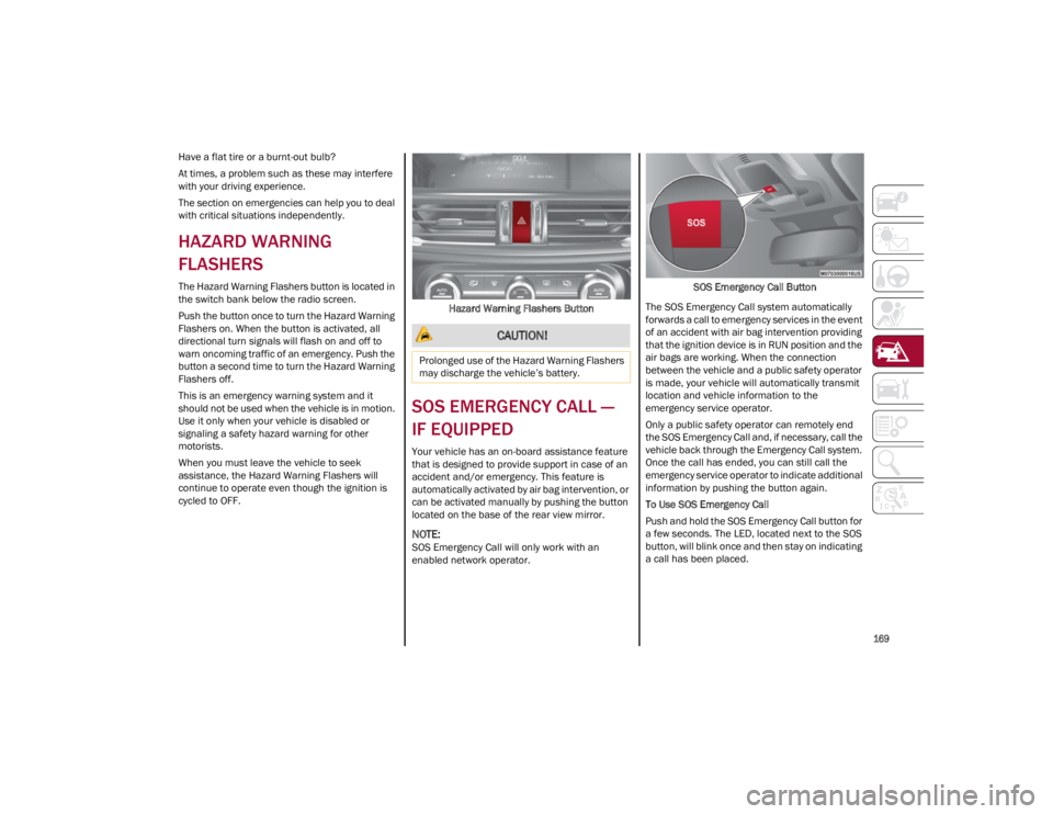
The Hazard Warning Flashers button is located in
the switch bank below the radio screen.
Push the button once to turn the Hazard Warning
Flashers on. When the button is activated, all
directional turn signals will flash on and off to
warn oncoming traffic of an emergency. Push the
button a second time to turn the Hazard Warning
Flashers off.
This is an emergency warning system and it
should not be used when the vehicle is in motion.
Use it only when your vehicle is disabled or
signaling a safety hazard warning for other
motorists.
When you must leave the vehicle to seek
assistance, the Hazard Warning Flashers will
continue to operate even though the ignition is
cycled to OFF.Hazard Warning Flashers Button
SOS EMERGENCY CALL —
IF EQUIPPED
Your vehicle has an on-board assistance feature
that is designed to provide support in case of an
accident and/or emergency. This feature is
automatically activated by air bag intervention, or
can be activated manually by pushing the button
located on the base of the rear view mirror.
NOTE:
SOS Emergency Call will only work with an
enabled network operator. SOS Emergency Call Button
The SOS Emergency Call system automatically
forwards a call to emergency services in the event
of an accident with air bag intervention providing
that the ignition device is in RUN position and the
air bags are working. When the connection
between the vehicle and a public safety operator
is made, your vehicle will automatically transmit
location and vehicle information to the
emergency service operator.
Only a public safety operator can remotely end
the SOS Emergency Call and, if necessary, call the
vehicle back through the Emergency Call system.
Once the call has ended, you can still call the
emergency service operator to indicate additional
information by pushing the button again.
To Use SOS Emergency Call
Push and hold the SOS Emergency Call button for
a few seconds. The LED, located next to the SOS
button, will blink once and then stay on indicating
a call has been placed.
CAUTION!
Prolonged use of the Hazard Warning Flashers
may discharge the vehicle’s battery.
23_GA_OM_EN_USC_t.book Page 169
Page 172 of 248
IN CASE OF EMERGENCY
170
NOTE:
If the SOS EmergencySOS Emergency Call button
is accidentally pushed, there is a 10 second delay
before the call is placed. The system will issue a
verbal alert that a call is about to be made. To
cancel the call connection, push the SOS Emer-
gency Call button again.
Once a connection between the vehicle and an
emergency service operator is made, the SOS
Emergency Call system will transmit the following
important vehicle information to the operator:
Indication that the occupant placed an SOS
Emergency Call.
The Vehicle Identification Number (VIN).
The last known GPS coordinates of the vehicle.
You will then be able to speak with the emergency
service operator to determine if additional help is
needed.
The SOS Emergency Call has priority over other
audio sources, which will be muted. If you have a
phone connected via Bluetooth®, it is discon -
nected and reconnected at the end of the SOS
Emergency Call. Voice prompts will guide you
during the SOS Emergency Call. If a connection is
made between an emergency service operator
and your vehicle, emergency service operators
may record conversations and sounds within your
vehicle once a connection is made, and by using
the service you consent to having this information
shared.
NOTE:
If you have not subscribed to the SOS service or if
the service is not available or has expired, the
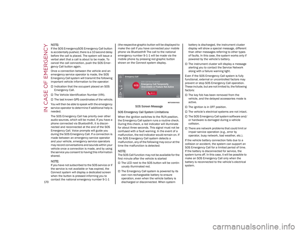
Connect system will display a dedicated screen
when the button is pressed informing you to
contact the national emergency number 9-1-1 (the respective graphic button will be displayed to
make the call if you have connected your mobile
phone via Bluetooth® The call to the national
emergency number 9-1-1 will be made via the
mobile phone by pressing red graphic button
shown on the Connect system display.
SOS Screen Message
SOS Emergency Call System Limitations
When the ignition switches to the RUN position,
the Emergency Call system runs a routine check.
During this check, a red indicator will illuminate
for about three seconds. This signal must not be
confused with a fault warning. In the event of a
malfunction, the red indicator would remain on. If
the SOS Emergency Call system detects a
malfunction, any of the following may occur at the
time the malfunction is detected:
NOTE:
The SOS Call function may not be available for the
first minute after the vehicle is started
The LED next to the SOS button will be contin -
uously illuminated red.
The Emergency Call system is powered by its
own non-rechargeable battery to ensure
operation, even when the vehicle battery is
discharged or disconnected. When system battery is discharged, the instrument cluster
display will show a special message, different
than other messages referring to other types
of faults. In this case, the system works only if
powered by the vehicle’s battery.
The instrument cluster will display a message
alerting you to contact the Service Network
along with a failure warning light.
Even if the SOS Emergency Call system is fully
functional, external or uncontrolled factors may
prevent or stop SOS Emergency Call operation.
These include, but are not limited to, the following
factors:
The key fob has been removed from the
vehicle, and the delayed accessories mode is
active.
The ignition is in OFF position.
The vehicle’s electrical systems are not intact.
The SOS Emergency Call system software and/
or hardware is damaged during a vehicle
collision.
There are network problems that could limit or
impair service operation (e.g., error by
operator, busy network, bad weather, etc.).
If the vehicle battery connection fails due to a
collision or accident, the system can support an
SOS Emergency Call for a limited period of time.
If the battery is disconnected for service, the
system turns off. In this case, it will be possible to
make an SOS Emergency Call only when the
battery is reconnected to the vehicle’s electrical
system.
23_GA_OM_EN_USC_t.book Page 170
Page 173 of 248
171
(Continued)
System Requirements
Vehicle must have an operable 4G network
connection.
Vehicle must be powered with a properly
functioning electrical system.
The ignition must be in the RUN or ACC
position.
Frequently Asked Questions:
What happens if I accidentally push the SOS
Emergency Call Button? You have 10 seconds
after pushing the emergency button to cancel the
call. To cancel the call, push the button again. What type of information is sent when I make an
SOS Emergency Call from my vehicle?
Certain
vehicle information, such as the VIN, is
transmitted along with last known GPS location.
Also note that emergency service operators may
record conversations and sounds within your
vehicle once a connection is made, and by using
the service you consent to having this information
shared.
When can I use the SOS Emergency Call
button? You can ONLY Use the SOS
Emergency Call button to make a call if
you or someone else needs emergency
assistance.
TIRE SERVICE KIT
DESCRIPTION
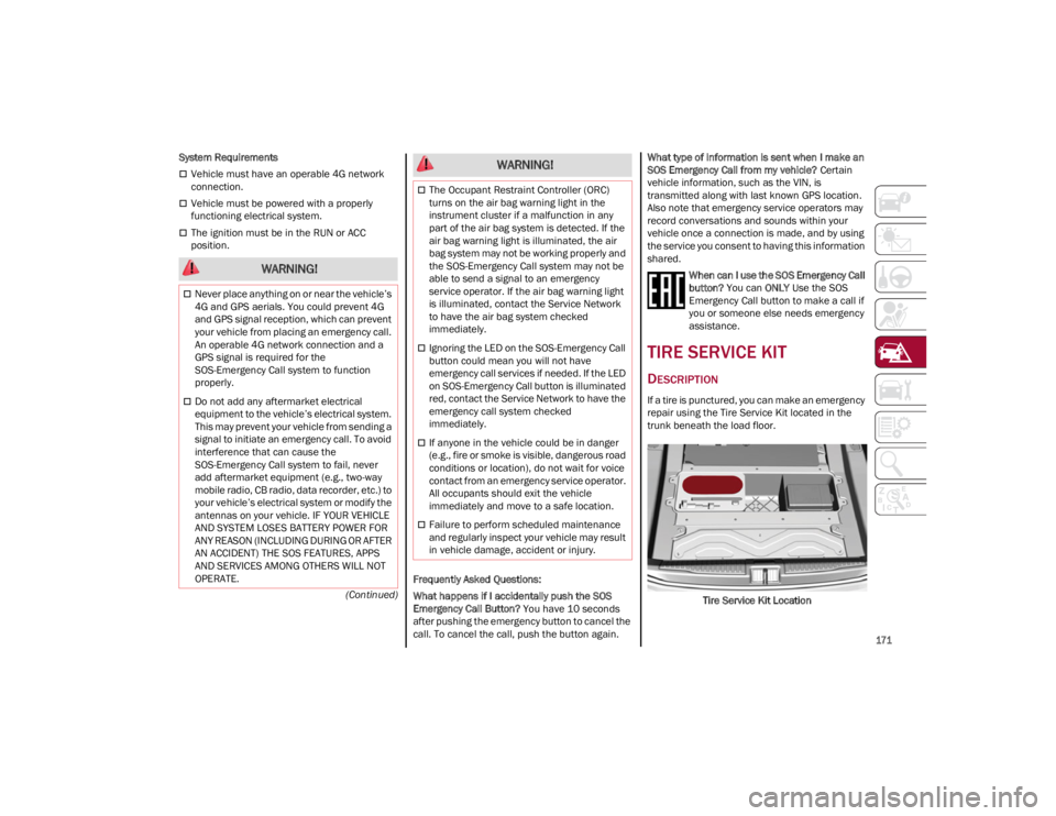
If a tire is punctured, you can make an emergency
repair using the Tire Service Kit located in the
trunk beneath the load floor.
Tire Service Kit Location
WARNING!
Never place anything on or near the vehicle’s
4G and GPS aerials. You could prevent 4G
and GPS signal reception, which can prevent
your vehicle from placing an emergency call.
An operable 4G network connection and a
GPS signal is required for the
SOS-Emergency Call system to function
properly.
Do not add any aftermarket electrical
equipment to the vehicle’s electrical system.
This may prevent your vehicle from sending a
signal to initiate an emergency call. To avoid
interference that can cause the
SOS-Emergency Call system to fail, never
add aftermarket equipment (e.g., two-way
mobile radio, CB radio, data recorder, etc.) to
your vehicle’s electrical system or modify the
antennas on your vehicle. IF YOUR VEHICLE
AND SYSTEM LOSES BATTERY POWER FOR
ANY REASON (INCLUDING DURING OR AFTER
AN ACCIDENT) THE SOS FEATURES, APPS
AND SERVICES AMONG OTHERS WILL NOT
OPERATE.
The Occupant Restraint Controller (ORC)
turns on the air bag warning light in the
instrument cluster if a malfunction in any
part of the air bag system is detected. If the
air bag warning light is illuminated, the air
bag system may not be working properly and
the SOS-Emergency Call system may not be
able to send a signal to an emergency
service operator. If the air bag warning light
is illuminated, contact the Service Network
to have the air bag system checked
immediately.
Ignoring the LED on the SOS-Emergency Call
button could mean you will not have
emergency call services if needed. If the LED
on SOS-Emergency Call button is illuminated
red, contact the Service Network to have the
emergency call system checked
immediately.
If anyone in the vehicle could be in danger
(e.g., fire or smoke is visible, dangerous road
conditions or location), do not wait for voice
contact from an emergency service operator.
All occupants should exit the vehicle
immediately and move to a safe location.
Failure to perform scheduled maintenance
and regularly inspect your vehicle may result
in vehicle damage, accident or injury.
WARNING!
23_GA_OM_EN_USC_t.book Page 171
Page 174 of 248
IN CASE OF EMERGENCY
172
(Continued)
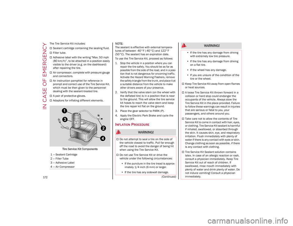
The Tire Service Kit includes:
Sealant cartridge containing the sealing fluid.
Filler tube.
Adhesive label with the writing "Max. 50 mph
(80 km/h)”, to be attached in a position easily
visible to the driver (e.g. on the dashboard)
after repairing the tire.
Air compressor, complete with pressure gauge
and connectors.
An instruction pamphlet for reference in
prompt and correct use of the Tire Service Kit,
which must be then given to the personnel
dealing with the sealant-treated tire.
A pair of protective gloves.
Adaptors for inflating different elements.
Tire Service Kit Components
NOTE:
The sealant is effective with external tempera -
tures of between -40°F (-40°C) and 122°F
(50°C). The sealant has an expiration date.
To use the Tire Service Kit, proceed as follows:
1. Stop the vehicle in a position where you can repair the tire safely. You should be as far as
possible from the side of the road, and in a posi -
tion that is not dangerous for oncoming traffic.
Activate the Hazard Warning Flashers, remove
the safety triangle from the trunk, and place it at
a suitable distance from the vehicle to make
other drivers aware of your presence.
2. Verify that the valve stem (on the wheel with the deflated tire) is in a position that is near
to the ground. This will allow the tire service
kit hoses to reach the valve stem and keep
the tire repair kit flat on the ground.
3. Place the gear selector to PARK (P).
4. Apply the Electric Park Brake and cycle the engine OFF.
INFLATION PROCEDURE
1 — Sealant Cartridge
2 — Filler Tube
3 — Adhesive Label
4 — Air Compressor
WARNING!
Do not attempt to seal a tire on the side of
the vehicle closest to traffic. Pull far enough
off the road to avoid the danger of being hit
when using the Tire Service Kit.
Do not use Tire Service Kit or drive the
vehicle under the following circumstances:
• If the puncture in the tire tread is approx-
imately 1/4 inch (6 mm) or larger.
• If the tire has any sidewall damage.
•If the tire has any damage from driving
with extremely low tire pressure.
• If the tire has any damage from driving
on a flat tire.
• If the wheel has any damage.
• If you are unsure of the condition of the
tire or the wheel.
Keep Tire Service Kit away from open flames
or heat sources.
A loose Tire Service Kit thrown forward in a
collision or hard stop could endanger the
occupants of the vehicle. Always stow the
Tire Service Kit in the place provided. Failure
to follow these warnings can result in injuries
that are serious or fatal to you, your
passengers, and others around you.
Take care not to allow the contents of Tire
Service Kit to come in contact with hair, eyes,
or clothing. Tire Service Kit sealant is harmful
if inhaled, swallowed, or absorbed through
the skin. It causes skin, eye, and respiratory
irritation. Flush immediately with plenty of
water if there is any contact with eyes or skin.
Change clothing as soon as possible, if there
is any contact with clothing.
Tire Service Kit Sealant solution contains
latex. In case of an allergic reaction or rash,
consult a physician immediately. Keep Tire
Service Kit out of reach of children. If
swallowed, rinse mouth immediately with
plenty of water and drink plenty of water. Do
not induce vomiting! Consult a physician
immediately.
WARNING!
23_GA_OM_EN_USC_t.book Page 172
Page 175 of 248
173
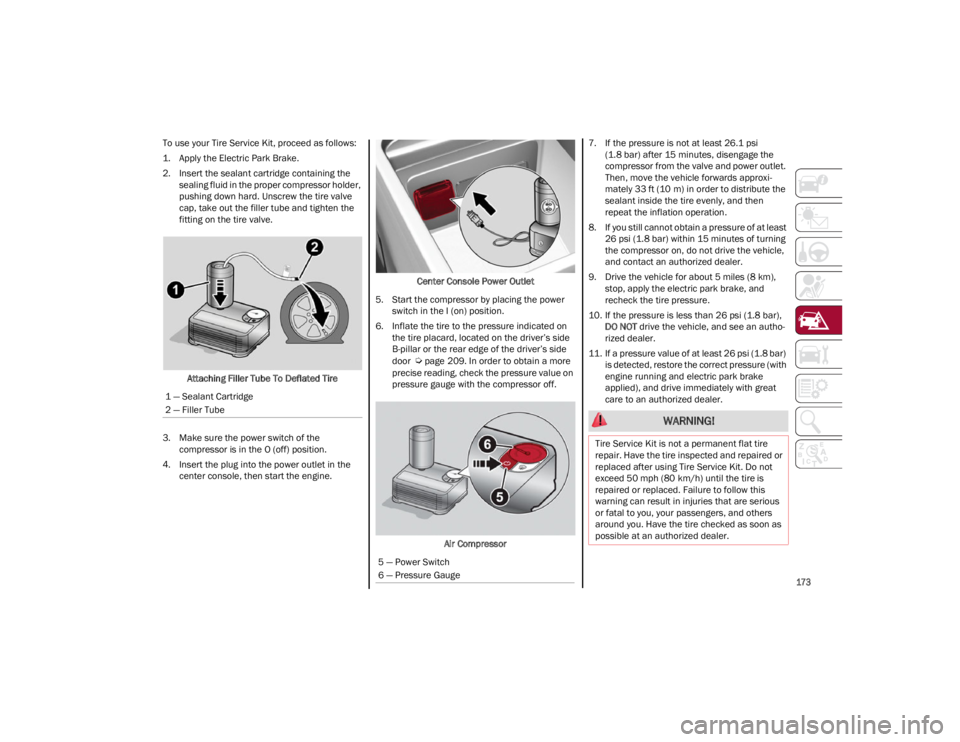
To use your Tire Service Kit, proceed as follows:
1. Apply the Electric Park Brake.
2. Insert the sealant cartridge containing the sealing fluid in the proper compressor holder,
pushing down hard. Unscrew the tire valve
cap, take out the filler tube and tighten the
fitting on the tire valve.
Attaching Filler Tube To Deflated Tire
3. Make sure the power switch of the compressor is in the O (off) position.
4. Insert the plug into the power outlet in the center console, then start the engine. Center Console Power Outlet
5. Start the compressor by placing the power switch in the I (on) position.
6. Inflate the tire to the pressure indicated on the tire placard, located on the driver’s side
B-pillar or the rear edge of the driver’s side
door
Ú
page 209. In order to obtain a more
precise reading, check the pressure value on
pressure gauge with the compressor off.
Air Compressor 7. If the pressure is not at least 26.1 psi
(1.8 bar) after 15 minutes, disengage the
compressor from the valve and power outlet.
Then, move the vehicle forwards approxi -
mately 33 ft (10 m) in order to distribute the sealant inside the tire evenly, and then
repeat the inflation operation.
8. If you still cannot obtain a pressure of at least 26 psi (1.8 bar) within 15 minutes of turning
the compressor on, do not drive the vehicle,
and contact an authorized dealer.
9. Drive the vehicle for about 5 miles (8 km), stop, apply the electric park brake, and
recheck the tire pressure.
10. If the pressure is less than 26 psi (1.8 bar), DO NOT drive the vehicle, and see an autho -
rized dealer.
11. If a pressure value of at least 26 psi (1.8 bar) is detected, restore the correct pressure (with
engine running and electric park brake
applied), and drive immediately with great
care to an authorized dealer.
1 — Sealant Cartridge
2 — Filler Tube
5 — Power Switch
6 — Pressure Gauge
WARNING!
Tire Service Kit is not a permanent flat tire
repair. Have the tire inspected and repaired or
replaced after using Tire Service Kit. Do not
exceed 50 mph (80 km/h) until the tire is
repaired or replaced. Failure to follow this
warning can result in injuries that are serious
or fatal to you, your passengers, and others
around you. Have the tire checked as soon as
possible at an authorized dealer.
23_GA_OM_EN_USC_t.book Page 173
Page 176 of 248
IN CASE OF EMERGENCY
174
12. Apply the adhesive label from the sealant bottle where it can be easily seen by the
driver as a reminder that the tire has been
treated with a Tire Service Kit, as well as not
to exceed the speed restriction for the
treated tire.
CHECKING AND RESTORING TIRE
P
RESSURE
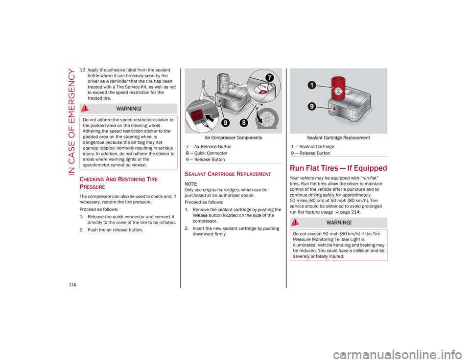
The compressor can also be used to check and, if
necessary, restore the tire pressure.
Proceed as follows:
1. Release the quick connector and connect it
directly to the valve of the tire to be inflated.
2. Push the air release button. Air Compressor Components
SEALANT CARTRIDGE REPLACEMENT
NOTE:
Only use original cartridges, which can be
purchased at an authorized dealer.
Proceed as follows:
1. Remove the sealant cartridge by pushing the
release button located on the side of the
compressor.
2. Insert the new sealant cartridge by pushing downward firmly. Sealant Cartridge Replacement
Run Flat Tires — If Equipped
Your vehicle may be equipped with “run flat”
tires. Run flat tires allow the driver to maintain
control of the vehicle after a puncture and to
continue driving safely for approximately
50 miles (80 km) at 50 mph (80 km/h). Tire
service should be obtained to avoid prolonged
run flat feature usage
Ú
page 214.
WARNING!
Do not adhere the speed restriction sticker to
the padded area on the steering wheel.
Adhering the speed restriction sticker to the
padded area on the steering wheel is
dangerous because the air bag may not
operate (deploy) normally resulting in serious
injury. In addition, do not adhere the sticker to
areas where warning lights or the
speedometer cannot be viewed.
7 — Air Release Button
8 — Quick Connector
9 — Release Button1 — Sealant Cartridge
9 — Release Button
WARNING!
Do not exceed 50 mph (80 km/h) if the Tire
Pressure Monitoring Telltale Light is
illuminated. Vehicle handling and braking may
be reduced. You could have a collision and be
severely or fatally injured.
23_GA_OM_EN_USC_t.book Page 174
Page 177 of 248
175
JUMP STARTING
If your vehicle has a discharged battery, it can be
jump started from the remote battery
connections by using a set of jumper cables and
a battery in another vehicle, or by using a portable
battery booster pack. Jump starting can be
dangerous if done improperly, so please follow
the procedures in this section carefully.
NOTE:
When using a portable battery booster pack,
follow the manufacturer's operating instructions
and precautions.
REMOTE BATTERY CONNECTION POSTS
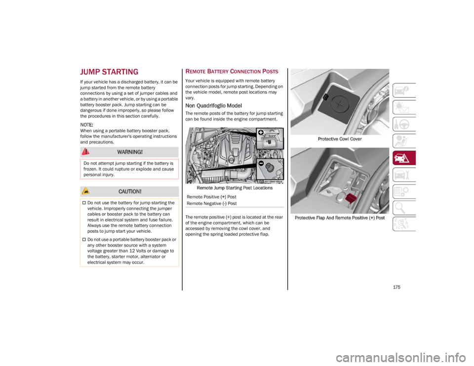
Your vehicle is equipped with remote battery
connection posts for jump starting. Depending on
the vehicle model, remote post locations may
vary.
Non Quadrifoglio Model
The remote posts of the battery for jump starting
can be found inside the engine compartment.Remote Jump Starting Post Locations
The remote positive (+) post is located at the rear
of the engine compartment, which can be
accessed by removing the cowl cover, and
opening the spring loaded protective flap. Protective Cowl Cover
Protective Flap And Remote Positive (+) Post
WARNING!
Do not attempt jump starting if the battery is
frozen. It could rupture or explode and cause
personal injury.
CAUTION!
Do not use the battery for jump starting the
vehicle. Improperly connecting the jumper
cables or booster pack to the battery can
result in electrical system and fuse failure.
Always use the remote battery connection
posts to jump start your vehicle.
Do not use a portable battery booster pack or
any other booster source with a system
voltage greater than 12 Volts or damage to
the battery, starter motor, alternator or
electrical system may occur.
Remote Positive (+) Post
Remote Negative (-) Post
23_GA_OM_EN_USC_t.book Page 175
Page 178 of 248
IN CASE OF EMERGENCY
176
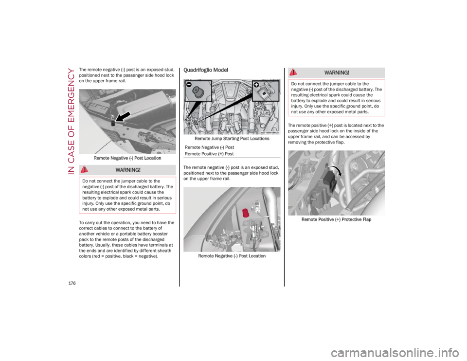
The remote negative (-) post is an exposed stud,
positioned next to the passenger side hood lock
on the upper frame rail.
Remote Negative (-) Post Location
To carry out the operation, you need to have the
correct cables to connect to the battery of
another vehicle or a portable battery booster
pack to the remote posts of the discharged
battery. Usually, these cables have terminals at
the ends and are identified by different sheath
colors (red = positive, black = negative).Quadrifoglio Model
Remote Jump Starting Post Locations
The remote negative (-) post is an exposed stud,
positioned next to the passenger side hood lock
on the upper frame rail.
Remote Negative (-) Post Location The remote positive
(+) post is located next to the
passenger side hood lock on the inside of the
upper frame rail, and can be accessed by
removing the protective flap.
Remote Positive (+) Protective Flap
WARNING!
Do not connect the jumper cable to the
negative (-) post of the discharged battery. The
resulting electrical spark could cause the
battery to explode and could result in serious
injury. Only use the specific ground point, do
not use any other exposed metal parts.
Remote Negative (-) Post
Remote Positive (+) Post
WARNING!
Do not connect the jumper cable to the
negative (-) post of the discharged battery. The
resulting electrical spark could cause the
battery to explode and could result in serious
injury. Only use the specific ground point, do
not use any other exposed metal parts.
23_GA_OM_EN_USC_t.book Page 176
Page 179 of 248
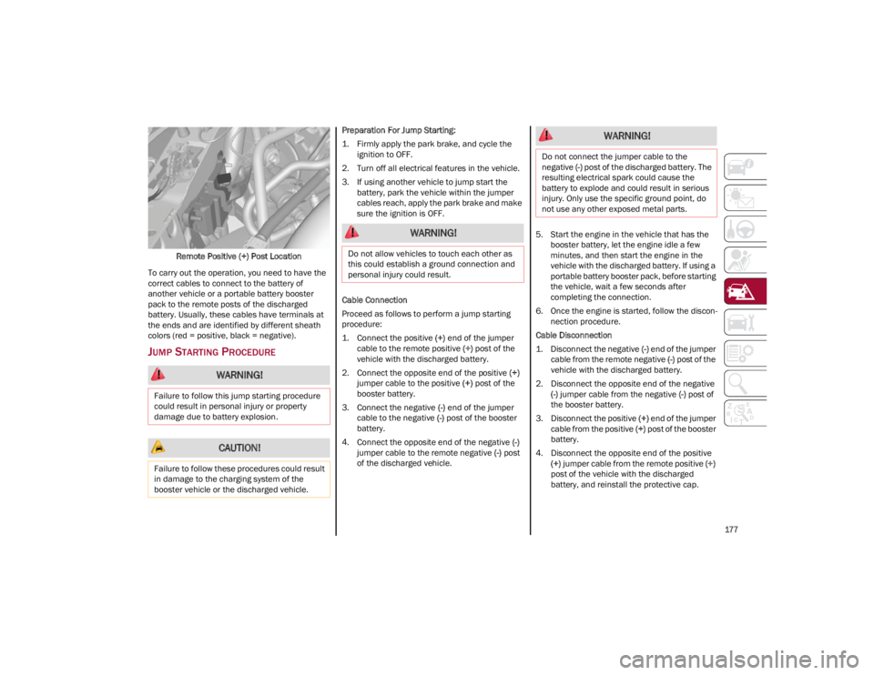
177
Remote Positive (+) Post Location
To carry out the operation, you need to have the
correct cables to connect to the battery of
another vehicle or a portable battery booster
pack to the remote posts of the discharged
battery. Usually, these cables have terminals at
the ends and are identified by different sheath
colors (red = positive, black = negative).
JUMP STARTING PROCEDURE
Preparation For Jump Starting:
1. Firmly apply the park brake, and cycle the ignition to OFF.
2. Turn off all electrical features in the vehicle.
3. If using another vehicle to jump start the battery, park the vehicle within the jumper
cables reach, apply the park brake and make
sure the ignition is OFF.
Cable Connection
Proceed as follows to perform a jump starting
procedure:
1. Connect the positive (+) end of the jumper
cable to the remote positive (+) post of the
vehicle with the discharged battery.
2. Connect the opposite end of the positive (+)
jumper cable to the positive (+) post of the
booster battery.
3. Connect the negative (-) end of the jumper
cable to the negative (-) post of the booster
battery.
4. Connect the opposite end of the negative (-)
jumper cable to the remote negative (-) post
of the discharged vehicle. 5. Start the engine in the vehicle that has the
booster battery, let the engine idle a few
minutes, and then start the engine in the
vehicle with the discharged battery. If using a
portable battery booster pack, before starting
the vehicle, wait a few seconds after
completing the connection.
6. Once the engine is started, follow the discon -
nection procedure.
Cable Disconnection
1. Disconnect the negative (-) end of the jumper
cable from the remote negative (-) post of the
vehicle with the discharged battery.
2. Disconnect the opposite end of the negative (-) jumper cable from the negative (-) post of
the booster battery.
3. Disconnect the positive (+) end of the jumper
cable from the positive (+) post of the booster
battery.
4. Disconnect the opposite end of the positive (+) jumper cable from the remote positive (+)
post of the vehicle with the discharged
battery, and reinstall the protective cap.
WARNING!
Failure to follow this jump starting procedure
could result in personal injury or property
damage due to battery explosion.
CAUTION!
Failure to follow these procedures could result
in damage to the charging system of the
booster vehicle or the discharged vehicle.
WARNING!
Do not allow vehicles to touch each other as
this could establish a ground connection and
personal injury could result.
WARNING!
Do not connect the jumper cable to the
negative (-) post of the discharged battery. The
resulting electrical spark could cause the
battery to explode and could result in serious
injury. Only use the specific ground point, do
not use any other exposed metal parts.
23_GA_OM_EN_USC_t.book Page 177
Page 180 of 248
IN CASE OF EMERGENCY
178
If frequent jump starting is required to start your
vehicle, you should have the battery and charging
system inspected at an authorized dealer.
BUMP STARTING
Never jump start the engine by pushing, towing or
coasting downhill.
NOTE:
You cannot start a vehicle with an automatic
transmission by pushing it.
IF YOUR ENGINE
OVERHEATS
Engine overheating may occur in situations of
extreme environmental temperatures, frequent
engine stops/starts, or driving in heavy traffic. If
the engine becomes overheated, the Engine
Temperature Warning Light in the instrument
cluster will illuminate along with a dedicated
message
Ú
page 70.If the vehicle is overheating, it will need to be
serviced by an authorized dealer.
In any of the following situations, you can reduce
the potential for overheating by taking the
appropriate action.
On the highways — slow down.
In city traffic — while stopped, place the
transmission in NEUTRAL, but do not increase
engine idle speed.
NOTE:
There are steps that you can take to slow down
an impending overheat condition:
If your Air Conditioner (A/C) is on, turn it off.
The A/C system adds heat to the engine
cooling system and turning the A/C off can
help remove this heat.
You can also turn the temperature control to
maximum heat, the mode control to floor and
the blower control to high. This allows the
heater core to act as a supplement to the
radiator and aids in removing heat from the
engine cooling system.
If Steam Is Coming From The Engine
Compartment
Do not go near the front of the vehicle. Stop the
engine. Wait until the steam dissipates. Then,
open the hood and start the engine.
If Neither Coolant Nor Steam Is Escaping
Open the hood and idle the engine until it cools.
NOTE:
If the cooling fan does not operate while the
engine is running, the engine temperature will
increase. Stop the engine and contact an
authorized dealer.
If the engine continues to overheat or
frequently overheats, have the cooling system
inspected. The engine could be seriously
damaged unless repairs are made. Contact an
authorized dealer.
CAUTION!
Accessories plugged into the vehicle power
outlets draw power from the vehicle’s battery,
even when not in use (i.e., cellular phones,
etc.). Eventually, if plugged in long enough
without engine operation, the vehicle’s battery
will discharge sufficiently to degrade battery
life and/or prevent the engine from starting.
WARNING!
You or others can be badly burned by hot
engine coolant (antifreeze) or steam from your
radiator. If you see or hear steam coming from
under the hood, do not open the hood until
the radiator has had time to cool. Never try to
open a cooling system pressure cap when the
radiator or coolant bottle is hot.
CAUTION!
Driving with a hot cooling system could
damage your vehicle. If temperature gauge
reads “H”, pull over and stop the vehicle. Idle
the vehicle with the air conditioner turned off
until the pointer drops back into the normal
range. If the pointer remains on the “H”, turn
the engine off immediately, and call for
service.
23_GA_OM_EN_USC_t.book Page 178