Alfa Romeo Giulietta 2014 Owner's Manual
Manufacturer: ALFA ROMEO, Model Year: 2014, Model line: Giulietta, Model: Alfa Romeo Giulietta 2014Pages: 280, PDF Size: 6.65 MB
Page 171 of 280
SNOW TYRESUse snow tyres of the same size as the
normal tyres provided with the car:
the Alfa Romeo Dealership will be able
to advise you on the most appropriate
tyre to use.
Only use these tyres in the event of ice
or snow on the roads.
110)
For the type of tyre to be used, inflation
pressures and the specifications of
snow tyres, follow the instructions given
in the "Wheels" paragraph in the
"Technical specifications" chapter.
The winter performance of these tyres
is considerably reduced when the tread
thickness is less than 4 mm. Replace
them in this case.
Due to the specific characteristics of
snow tyres, in normal weather
conditions or on long motorway
journeys, the performance of these
tyres is lower than that of standard
tyres. Their usage should therefore be
restricted in accordance with their
type approval.
All four tyres should be the same (brand
and track) to ensure greater safety
when driving and braking as well as
making the car more responsive. It is
inadvisable to change the rotation
direction of tyres.
WARNING
110) The maximum speed for snow
tyres marked “Q” is 160 km/h,
while it is 190 km/h for “T” tyres
and 210 km/h for "H" tyres. The
highway code speed limits must
however always be complied with.
SNOW CHAINSThe use of snow chains should be in
compliance with local regulations.
Snow chains can be fitted to the tyres
of the front wheels (drive wheels) only.
Check the tension of the snow chains
after the first few metres have been
driven.
Use low-clearance snow chains: on all
versions, for 195/55 R16", 205/55 R16"
and 225/45 R17" size tyres use
low-clearance snow chains with a
maximum projection beyond the tyre
profile of 9 mm.
23)
IMPORTANT The space-saver wheel
cannot be fitted with snow chains. If a
front (drive) wheel is punctured and
snow chains must be used, you must
remove a normal wheel from the rear
axle and replace it with the space-saver
wheel. In this way, with two normal
drive wheels, it is possible to use snow
chains.
167
Page 172 of 280
IMPORTANT
23) Keep your speed down when
snow chains are fitted; do not
exceed 50 km/h. Avoid potholes,
steps and pavements and avoid
driving for long distances on
roads not covered with snow to
prevent damaging the car and the
road surface.
STORING THE CARIf the car is to be left inactive for longer
than a month, the following precautions
should be noted:
❒park the car in covered, dry and if
possible well-ventilated premises and
slightly open the windows;
❒check that the handbrake is not
engaged;
❒disconnect the negative battery
terminal and check the battery
charge. Repeat this check once
every three months during storage;
❒if the battery is not disconnected
from the electrical system, checks its
state of charge every thirty days;
❒clean and protect the painted parts
using protective wax;
❒clean and protect the shiny metal
parts using special compounds
available commercially;
❒sprinkle talcum powder on the
windscreen and rear window wiper
rubber blades and lift them off the
glasses;
❒slightly open the windows;❒cover the car with a cloth or
perforated plastic sheet. Do not use
compact plastic sheets which do
not allow humidity to evaporate from
the surface of the car.
❒inflate tyres to +0.5 bar above the
standard prescribed pressure and
check it periodically;
❒do not drain the engine cooling
system;
❒Any time the car is left inactive for
two weeks or more, operate the
air conditioning system with engine
idling for at least 5 minutes, setting
external air and with fan at maximum
speed. This operation will ensure a
suitable lubrication to minimise
possibility of damage to the
compressor when the system is
operated again.
IMPORTANT After turning the ignition
key to STOP, wait at least 1 minute
before disconnecting the electrical
supply to the battery.
168
STARTING AND DRIVING
Page 173 of 280
IN AN EMERGENCY
A punctured tyre or a burnt-out bulb?
At times, a problem may interfere
with our journey.
The pages on emergencies can help
you to deal with critical situations
independently and with calm.
In an emergency we recommend that
you call the freephone number found in
the Warranty Booklet.
It is also possible to call the 00 800
2532 4200 freephone number to
search the nearest Alfa Romeo
Authorised Network.STARTING THE ENGINE .................1
REPLACING A WHEEL ...................171
"FIX&GO AUTOMATIC" KIT .............17
CHANGING A BULB .......................179
REPLACING EXTERIOR BULBS......183
INTERIOR BULB REPLACEMENT ...186
REPLACING FUSES........................187
BATTERY RECHARGING ................196
RAISING THE CAR..........................197
TOWING THE CAR .........................19
169
70
6
7
Page 174 of 280
STARTING THE
ENGINEContact the Alfa Romeo Dealership
immediately if the warning light
stays on constantly on the
instrument panel.
JUMP STARTING
If the battery is flat, start the engine
using an auxiliary battery with the same
capacity or a little higher than the flat
one.
24) 25)
111)
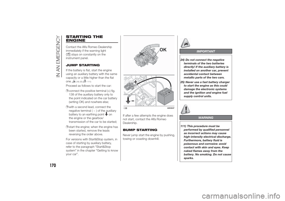
Proceed as follows to start the car:
❒connect the positive terminal (+) fig.
138 of the auxiliary battery only to
the point indicated on the car battery
(writing OK) and nowhere else;
❒with a second lead, connect the
negative terminal(−)oftheauxiliary
battery to an earthing point
on
the engine or the gearbox/
transmission of the car to be started;
❒start the engine; when the engine has
been started, remove the leads
reversing the order above.
For versions with Start&Stop system, in
case of starting by auxiliary battery,
refer to the paragraph “Start&Stop
system” in the chapter “Getting to know
your car”.If after a few attempts the engine does
not start, contact the Alfa Romeo
Dealership.
BUMP STARTING
Never jump start the engine by pushing,
towing or coasting downhill.
IMPORTANT
24) Do not connect the negative
terminals of the two batteries
directly! If the auxiliary battery is
installed on another car, prevent
accidental contact between
metallic parts of the two cars.
25) Never use a fast battery charger
to start the engine as this could
damage the electronic systems
and the ignition and engine fuel
supply control units.
WARNING
111) This procedure must be
performed by qualified personnel
as incorrect actions may cause
high-intensity electrical discharge.
Furthermore, battery fluid is
poisonous and corrosive: avoid
contact with skin and eyes. Keep
naked flames away from the
battery. No smoking. Do not cause
sparks.
138
A0K0247
170
IN AN EMERGENCY
Page 175 of 280
REPLACING A
WHEELGENERAL
INSTRUCTIONS
The car is equipped with the “Fix&Go
Automatic Kit”: see the paragraph
“Fix&Go Automatic Kit” for how to use
this device.
As an alternative to the “Fix&Go
Automatic Kit” the car may be
requested with a space-saver wheel:
see the instructions on the following
pages for changing the wheel.
112) 113) 114) 115) 116)
JACK
Please note that:
❒the jack weight is 1.76 kg;
❒the jack requires no adjustment;
❒the jack cannot be repaired and in
the event of a fault it must be
replaced by another original one;
❒no tool other than its cranking device
may be fitted on the jack.
To change a wheel, proceed as follows:❒stop the car in a position that is not
dangerous for oncoming traffic
where you can change the wheel
safely. The ground should be flat
if possible, and sufficiently firm;
❒switch off the engine, pull up the
handbrake and engage the 1
stgear
or reverse. Wear the reflective safety
jacket (compulsory by law) before
getting out of the car;
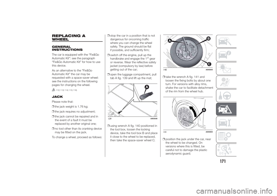
❒open the luggage compartment, pull
tab A fig. 139 and lift up the mat;
❒using wrench A fig. 140 positioned in
the tool box, loosen the locking
device, take the tool box B and place
it close to the wheel to be replaced,
then take the space-saver wheel C;❒take the wrench A fig. 141 and
loosen the fixing bolts by about one
turn. For versions with alloy rims,
shake the car to facilitate detachment
of the rim from the wheel hub.
❒position the jack under the car, near
the wheel to be changed. On
versions where this is fitted, be
careful not to damage the plastic
aerodynamic guard;
139
A0K0648
140
A0K0649
141
A0K0650
171
Page 176 of 280
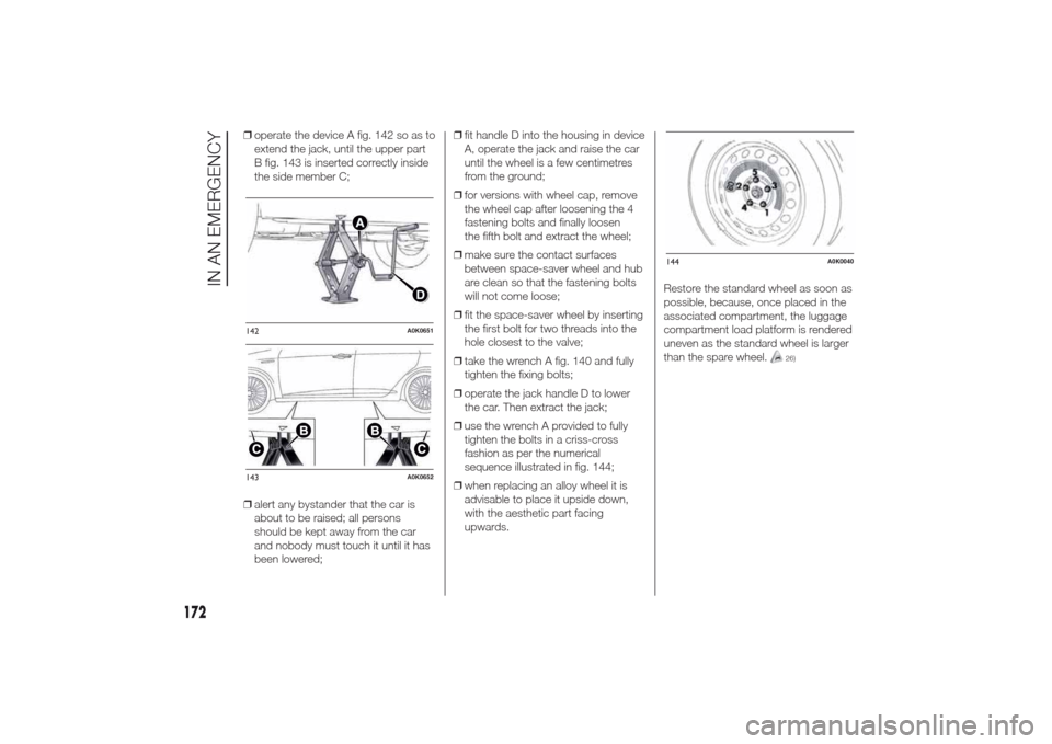
❒operate the device A fig. 142 so as to
extend the jack, until the upper part
B fig. 143 is inserted correctly inside
the side member C;
❒alert any bystander that the car is
about to be raised; all persons
should be kept away from the car
and nobody must touch it until it has
been lowered;❒fit handle D into the housing in device
A, operate the jack and raise the car
until the wheel is a few centimetres
from the ground;
❒for versions with wheel cap, remove
the wheel cap after loosening the 4
fastening bolts and finally loosen
the fifth bolt and extract the wheel;
❒make sure the contact surfaces
between space-saver wheel and hub
are clean so that the fastening bolts
will not come loose;
❒fit the space-saver wheel by inserting
the first bolt for two threads into the
hole closest to the valve;
❒take the wrench A fig. 140 and fully
tighten the fixing bolts;
❒operate the jack handle D to lower
the car. Then extract the jack;
❒use the wrench A provided to fully
tighten the bolts in a criss-cross
fashion as per the numerical
sequence illustrated in fig. 144;
❒when replacing an alloy wheel it is
advisable to place it upside down,
with the aesthetic part facing
upwards.Restore the standard wheel as soon as
possible, because, once placed in the
associated compartment, the luggage
compartment load platform is rendered
uneven as the standard wheel is larger
than the spare wheel.
26)
142
A0K0651
143
A0K0652
144
A0K0040
172
IN AN EMERGENCY
Page 177 of 280
REMOVING THE
SUBWOOFER (versions
with Bose HI-FI system)
(for versions/markets, where provided)
IMPORTANT The following procedure
only applies to cars equipped with
Bose HI-FI systems with subwoofer (for
versions/markets, where provided).
Subwoofer and
space-saver spare
wheel
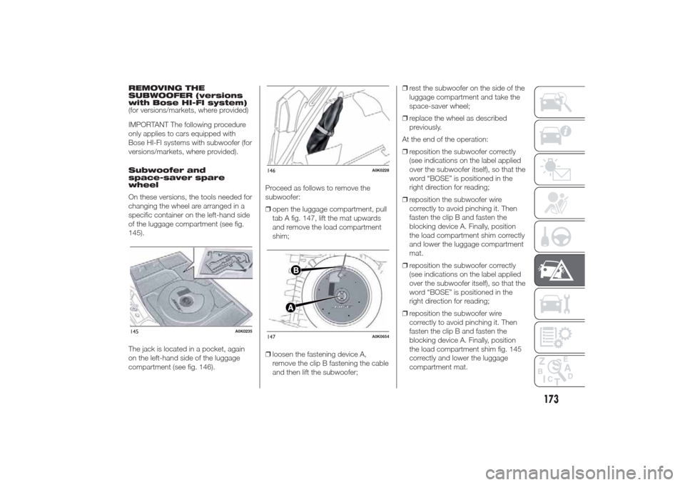
On these versions, the tools needed for
changing the wheel are arranged in a
specific container on the left-hand side
of the luggage compartment (see fig.
145).
The jack is located in a pocket, again
on the left-hand side of the luggage
compartment (see fig. 146).Proceed as follows to remove the
subwoofer:
❒open the luggage compartment, pull
tab A fig. 147, lift the mat upwards
and remove the load compartment
shim;
❒loosen the fastening device A,
remove the clip B fastening the cable
and then lift the subwoofer;❒rest the subwoofer on the side of the
luggage compartment and take the
space-saver wheel;
❒replace the wheel as described
previously.
At the end of the operation:
❒reposition the subwoofer correctly
(see indications on the label applied
over the subwoofer itself), so that the
word “BOSE” is positioned in the
right direction for reading;
❒reposition the subwoofer wire
correctly to avoid pinching it. Then
fasten the clip B and fasten the
blocking device A. Finally, position
the load compartment shim correctly
and lower the luggage compartment
mat.
❒reposition the subwoofer correctly
(see indications on the label applied
over the subwoofer itself), so that the
word “BOSE” is positioned in the
right direction for reading;
❒reposition the subwoofer wire
correctly to avoid pinching it. Then
fasten the clip B and fasten the
blocking device A. Finally, position
the load compartment shim fig. 145
correctly and lower the luggage
compartment mat.145
A0K0235
146
A0K0228
147
A0K0654
173
Page 178 of 280
Subwoofer and "Fix&Go
Automatic Kit"
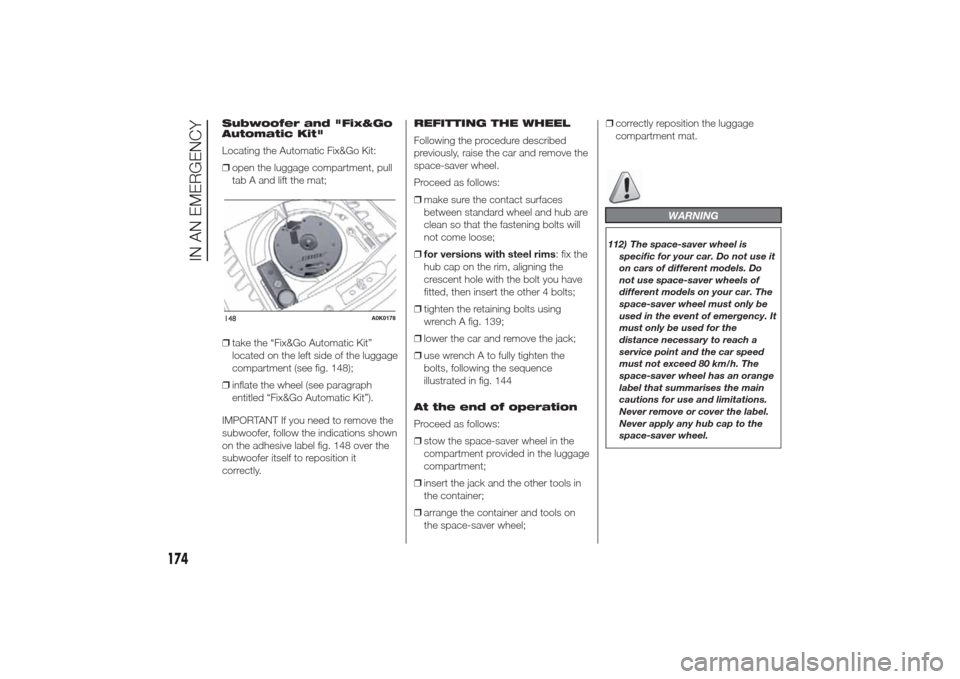
Locating the Automatic Fix&Go Kit:
❒open the luggage compartment, pull
tab A and lift the mat;
❒take the “Fix&Go Automatic Kit”
located on the left side of the luggage
compartment (see fig. 148);
❒inflate the wheel (see paragraph
entitled “Fix&Go Automatic Kit”).
IMPORTANT If you need to remove the
subwoofer, follow the indications shown
on the adhesive label fig. 148 over the
subwoofer itself to reposition it
correctly.REFITTING THE WHEEL
Following the procedure described
previously, raise the car and remove the
space-saver wheel.
Proceed as follows:
❒make sure the contact surfaces
between standard wheel and hub are
clean so that the fastening bolts will
not come loose;
❒for versions with steel rims: fix the
hub cap on the rim, aligning the
crescent hole with the bolt you have
fitted, then insert the other 4 bolts;
❒tighten the retaining bolts using
wrench A fig. 139;
❒lower the car and remove the jack;
❒use wrench A to fully tighten the
bolts, following the sequence
illustrated in fig. 144
At the end of operation
Proceed as follows:
❒stow the space-saver wheel in the
compartment provided in the luggage
compartment;
❒insert the jack and the other tools in
the container;
❒arrange the container and tools on
the space-saver wheel;❒correctly reposition the luggage
compartment mat.
WARNING
112) The space-saver wheel is
specific for your car. Do not use it
on cars of different models. Do
not use space-saver wheels of
different models on your car. The
space-saver wheel must only be
used in the event of emergency. It
must only be used for the
distance necessary to reach a
service point and the car speed
must not exceed 80 km/h. The
space-saver wheel has an orange
label that summarises the main
cautions for use and limitations.
Never remove or cover the label.
Never apply any hub cap to the
space-saver wheel.
148
A0K0178
174
IN AN EMERGENCY
Page 179 of 280
113) Use your hazard lights, warning
triangle, etc to show that your car
is stationary. Passengers should
get out of the car, particularly if it
is heavily loaded, and wait for
the wheel to be changed away
from the traffic. In the event of a
wheel change on a slope or on
unsurfaced roads, chock the
wheels.
114) Car handling is modified with
the space-saver wheel fitted.
Avoid violent acceleration and
braking, abrupt steering and fast
cornering. The overall duration
of the space-saver wheel is of
about 3000 km, after which the
relevant tyre must be replaced
with another one of the same
type. Never install a traditional
tyre on a rim designed to be used
as a space-saver wheel. Have
the wheel repaired and refitted as
soon as possible. Using two or
more space-saver wheels at the
same time is forbidden. Do not
grease the bolt threads before you
fit them, because they could
suddenly come loose.115) Use the jack only to replace
wheels on the car with which it
is supplied or on other cars of the
same model. Never use the jack
for other purposes, such as lifting
other car models. Never use it
for repair operations under the
car. Incorrect positioning of the
jack may cause the car to fall. Do
not use the jack for loads higher
than those shown on the label.
Never install snow chains on the
space-saver wheel; if a front tyre
(driving wheel) is punctured and
you need to use snow chains, use
a standard wheel from the rear
axle and install the space-saver
wheel on the rear axle. In this
way, with two normal front drive
wheels, it is possible to use snow
chains.
116) Incorrect hub cap assembly
may cause it to come off when the
car is moving. Never tamper with
the inflation valve. Never
introduce tools of any kind
between rim and tyre. Regularly
check the inflation pressure of the
tyres and space-saver wheel
(see chapter "Technical
specifications").
IMPORTANT
26) Contact an Alfa Romeo
Dealership as soon as possible to
have the correct tightening of
the wheel bolts checked.
175
Page 180 of 280
"Fix&Go Automatic"
kitThis is located in the luggage
compartment (the kit container may
vary according to version - see fig.
149).
The kit also contains a screwdriver and
a tow hook.
The kit also contains:❒bottle A fig. 150 containing sealant
and fitted with: filling tube B and
adhesive label C with the wording
“max. 80 km/h” to be placed in
a clearly visible position (e.g. on the
dashboard) after repairing the tyre;
❒a compressor D complete with
pressure gauge and connectors;
❒an information leaflet fig. 151,
providing instructions for using the kit
correctly. This booklet should be
given to the persons charged with
handling the tyre treated with this kit;
❒a pair of gloves located in the side
compartment of the compressor;
❒adapters for inflating different
elements.
2)117) 118) 120)
IMPORTANT The sealing liquid is
suitable for use at temperatures in the
range from –20°C to +50°C. The
sealant has an expiry date.
INFLATION PROCEDURE
119) 121) 122) 123) 124) 125)
Proceed as follows:
❒engage the handbrake, unscrew the
tyre valve cap, take out filler hose A
fig. 152 and tighten ring nut B on the
tyre valve;
❒make sure that switch A for the
compressor is in position0(off), start
the engine, insert the plug into the
luggage compartment power socket
(see fig. 154) or on central tunnel
(see fig. 155) and switch on the
compressor by bringing switch A to
positionI(on);
149
A0K0515
150
A0K0516
151
A0K0517
176
IN AN EMERGENCY