lock Alfa Romeo MiTo 2012 Owner handbook (in English)
[x] Cancel search | Manufacturer: ALFA ROMEO, Model Year: 2012, Model line: MiTo, Model: Alfa Romeo MiTo 2012Pages: 262, PDF Size: 6.46 MB
Page 171 of 262
170IN AN EMERGENCY
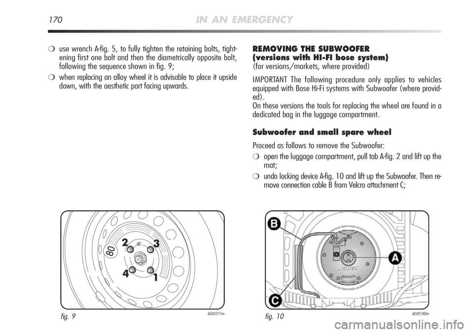
fig. 9A0J0271mfig. 10A0J0180m
❍use wrench A-fig. 5, to fully tighten the retaining bolts, tight-
ening first one bolt and then the diametrically opposite bolt,
following the sequence shown in fig. 9;
❍when replacing an alloy wheel it is advisable to place it upside
down, with the aesthetic part facing upwards.
REMOVING THE SUBWOOFER
(versions with HI-FI bose system)
(for versions/markets, where provided)
IMPORTANT The following procedure only applies to vehicles
equipped with Bose Hi-Fi systems with Subwoofer (where provid-
ed).
On these versions the tools for replacing the wheel are found in a
dedicated bag in the luggage compartment.
Subwoofer and small spare wheel
Proceed as follows to remove the Subwoofer:
❍open the luggage compartment, pull tab A-fig. 2 and lift up the
mat;
❍undo locking device A-fig. 10 and lift up the Subwoofer. Then re-
move connection cable B from Velcro attachment C;
Page 172 of 262
IN AN EMERGENCY171
4
❍rest the Subwoofer to one side in the luggage compartment,
remove the container and take out the small spare wheel;
❍replace the wheel as described previously.
After tyre replacement:
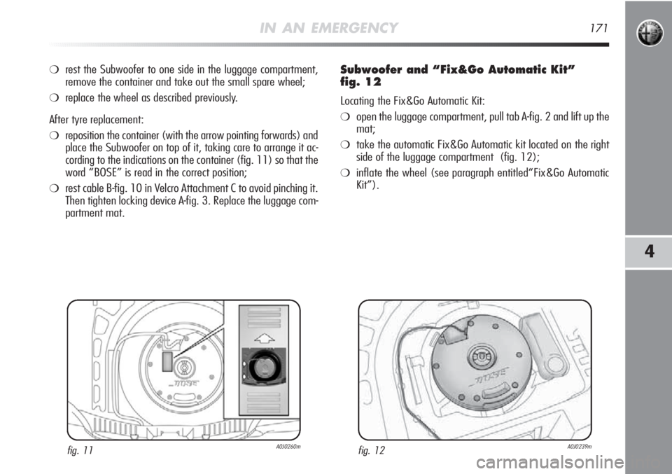
❍reposition the container (with the arrow pointing forwards) and
place the Subwoofer on top of it, taking care to arrange it ac-
cording to the indications on the container (fig. 11) so that the
word “BOSE” is read in the correct position;
❍rest cable B-fig. 10 in Velcro Attachment C to avoid pinching it.
Then tighten locking device A-fig. 3. Replace the luggage com-
partment mat.
Subwoofer and “Fix&Go Automatic Kit”
fig. 12
Locating the Fix&Go Automatic Kit:
❍open the luggage compartment, pull tab A-fig. 2 and lift up the
mat;
❍take the automatic Fix&Go Automatic kit located on the right
side of the luggage compartment (fig. 12);
❍inflate the wheel (see paragraph entitled“Fix&Go Automatic
Kit”).
fig. 11A0J0260mfig. 12A0J0239m
Page 178 of 262
IN AN EMERGENCY177
4
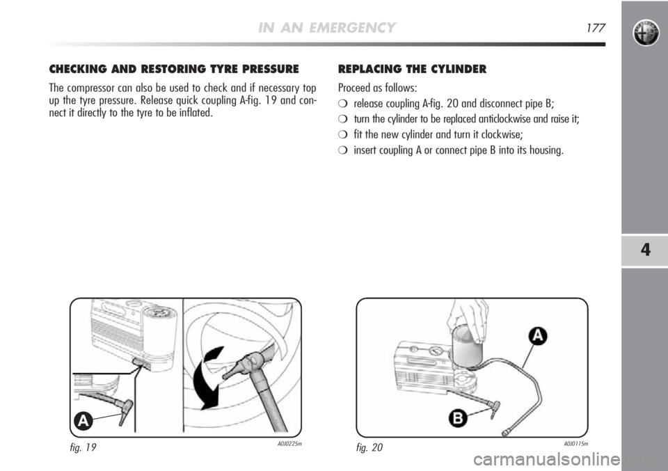
fig. 19A0J0225m
A
CHECKING AND RESTORING TYRE PRESSURE
The compressor can also be used to check and if necessary top
up the tyre pressure. Release quick coupling A-fig. 19 and con-
nect it directly to the tyre to be inflated.
REPLACING THE CYLINDER
Proceed as follows:
❍release coupling A-fig. 20 and disconnect pipe B;
❍turn the cylinder to be replaced anticlockwise and raise it;
❍fit the new cylinder and turn it clockwise;
❍insert coupling A or connect pipe B into its housing.
fig. 20A0J0115m
Page 179 of 262
178IN AN EMERGENCY
CHANGING A BULB
GENERAL INSTRUCTIONS
❍Before changing a bulb check the contacts for oxidation;
❍blown bulbs must be replaced with others of the same type and
power;
❍After replacing a headlight bulb, always check its alignment;
❍When a bulb is not working, check that the corresponding fuse
is intact before replacing it: refer to the “Replacing fuses” para-
graph in this section for the location of fuses.
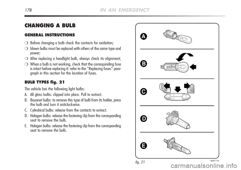
BULB TYPES fig. 21
The vehicle has the following light bulbs:
A. All glass bulbs: clipped into place. Pull to extract.
B. Bayonet bulbs: to remove this type of bulb from its holder, press
the bulb and turn it anticlockwise.
C. Cylindrical bulbs: release from the contacts to extract.
D. Halogen bulbs: release the fastening clip from the corresponding
seat to remove the bulb.
E. Halogen bulbs: release the fastening clip from the corresponding
seat to remove the bulb.
fig. 21A0J0117m
Page 182 of 262
IN AN EMERGENCY181
4
DIPPED BEAM HEADLIGHTS
With incandescent bulb
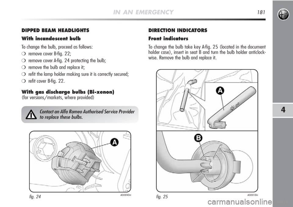
To change the bulb, proceed as follows:
❍remove cover B-fig. 22;
❍remove cover A-fig. 24 protecting the bulb;
❍remove the bulb and replace it;
❍refit the lamp holder making sure it is correctly secured;
❍refit cover B-fig. 22.
With gas discharge bulbs (Bi-xenon)
(for versions/markets, where provided)
DIRECTION INDICATORS
Front indicators
To change the bulb take key A-fig. 25 (located in the document
holder case), insert in seat B and turn the bulb holder anticlock-
wise. Remove the bulb and replace it.
fig. 24A0J0040m
Contact an Alfa Romeo Authorised Service Provider
to replace these bulbs.
fig. 25A0J0018m
Page 183 of 262
182IN AN EMERGENCY
Side indicators
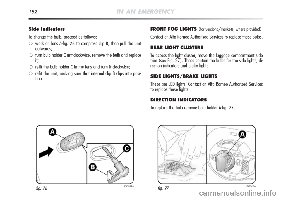
To change the bulb, proceed as follows:
❍work on lens A-fig. 26 to compress clip B, then pull the unit
outwards;
❍turn bulb holder C anticlockwise, remove the bulb and replace
it;
❍refit the bulb holder C in the lens and turn it clockwise;
❍refit the unit, making sure that internal clip B clips into posi-
tion.
FRONT FOG LIGHTS(for versions/markets, where provided)
Contact an Alfa Romeo Authorised Services to replace these bulbs.
REAR LIGHT CLUSTERS
To access the light cluster, move the luggage compartment side
trim (see Fig. 27). These contain the bulbs for the side lights, di-
rection indicators and brake lights.
SIDE LIGHTS/BRAKE LIGHTS
These are LED lights. Contact an Alfa Romeo Authorised Services
to replace these lights.
DIRECTION INDICATORS
To replace the bulb remove bulb holder A-fig. 27.
fig. 26A0J0042mfig. 27A0J0043m
Page 184 of 262
IN AN EMERGENCY183
4
REAR FOG LIGHTS/REVERSING LIGHTS
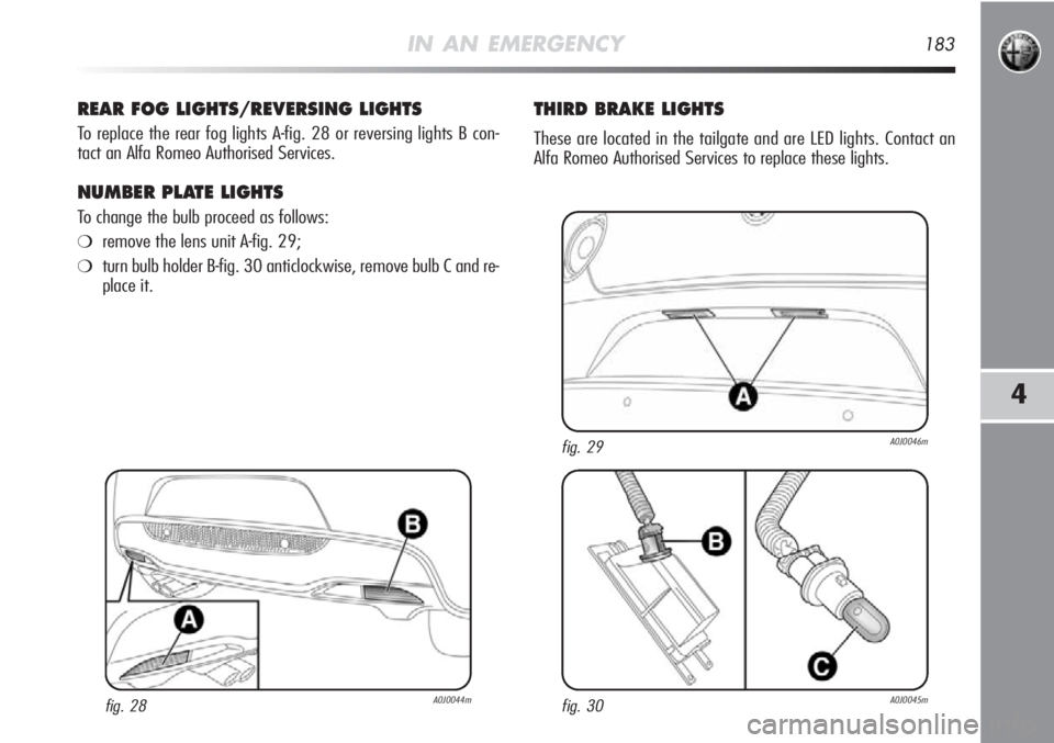
To replace the rear fog lights A-fig. 28 or reversing lights B con-
tact an Alfa Romeo Authorised Services.
NUMBER PLATE LIGHTS
To change the bulb proceed as follows:
❍remove the lens unit A-fig. 29;
❍turn bulb holder B-fig. 30 anticlockwise, remove bulb C and re-
place it.
THIRD BRAKE LIGHTS
These are located in the tailgate and are LED lights. Contact an
Alfa Romeo Authorised Services to replace these lights.
fig. 28A0J0044mfig. 30A0J0045m
fig. 29A0J0046m
Page 187 of 262
186IN AN EMERGENCY
SUN VISOR COURTESY LIGHT
(for versions/markets, where provided)
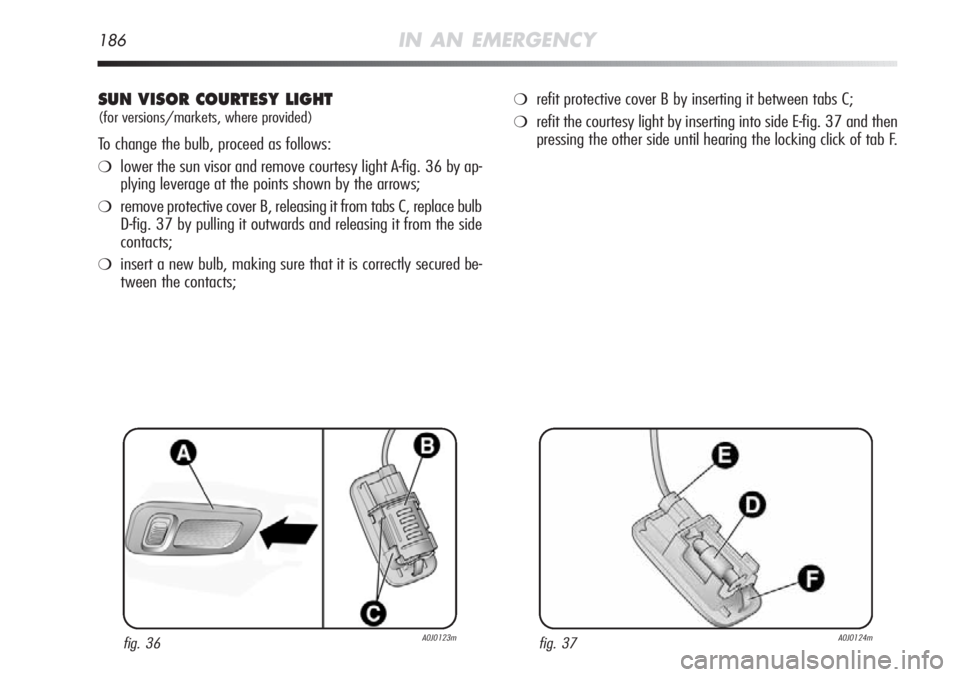
To change the bulb, proceed as follows:
❍lower the sun visor and remove courtesy light A-fig. 36 by ap-
plying leverage at the points shown by the arrows;
❍remove protective cover B, releasing it from tabs C, replace bulb
D-fig. 37 by pulling it outwards and releasing it from the side
contacts;
❍insert a new bulb, making sure that it is correctly secured be-
tween the contacts;
❍refit protective cover B by inserting it between tabs C;
❍refit the courtesy light by inserting into side E-fig. 37 and then
pressing the other side until hearing the locking click of tab F.
fig. 36A0J0123mfig. 37A0J0124m
Page 188 of 262
IN AN EMERGENCY187
4
DOOR LIGHTS
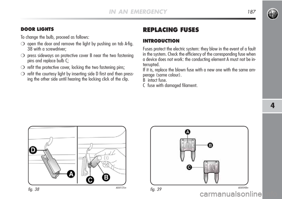
To change the bulb, proceed as follows:
❍open the door and remove the light by pushing on tab A-fig.
38 with a screwdriver;
❍press sideways on protective cover B near the two fastening
pins and replace bulb C;
❍refit the protective cover, locking the two fastening pins;
❍refit the courtesy light by inserting side D first and then press-
ing the other side until hearing the locking click of the clip.
REPLACING FUSES
INTRODUCTION
Fuses protect the electric system: they blow in the event of a fault
in the system. Check the efficiency of the corresponding fuse when
a device does not work: the conducting element A must not be in-
terrupted.
If it is, replace the blown fuse with a new one with the same am-
perage (same colour).
B intact fuse.
C fuse with damaged filament.
fig. 39A0J0048mfig. 38A0J0125m
Page 195 of 262

F38
F43
F47
F48
F4915
20
20
20
543
43
43
43
43
194IN AN EMERGENCY
CONSUMERS FUSE AMPERE FIGURE
Door lock motor on door,
Safe Lock motor on doors,
Tailgate unlocking motor
Windscreen / rearscreen washer pump
Electric window motor complete with
control unit (driver-side door)
Electric window motor complete with
control unit (passenger-side door)
Parking sensors control unit, Tyre pressure
detection control unit, Rain/dusk sensor
on rear-view mirror, Electro-chrome sensor
on rear-view mirror, Seat belts fastened
warning light display on rear-view mirror,
Control panel illumination (Central control
panel, Driver-side control panel, Steering wheel
control panel, Blue&Me
TMcontrol panel),
Front seat heating pad activation switch,
Alarm system volume-sensing sensors control unit,
Electric sunroof control unit,
PND socket on dashboard