dashboard Alfa Romeo MiTo 2013 Owner handbook (in English)
[x] Cancel search | Manufacturer: ALFA ROMEO, Model Year: 2013, Model line: MiTo, Model: Alfa Romeo MiTo 2013Pages: 312, PDF Size: 11.5 MB
Page 7 of 312

GETTING TO KNOW YOUR CAR
DASHBOARDThe presence and position of the controls, instruments and indicators may vary according to the different versions.1. Diffuser for directing air to the side windows 2. Adjustable air vent 3. Exterior light control lever 4. Instrument panel 5. Windscreen wiper/rear
window wiper/trip computer control lever 6. Car radio (for versions/markets, where provided) 7. Adjustable air diffusers 8. Hazard warning lights,
door locking/unlocking button 9. Passenger front airbag 10. Glove compartment 11. Heating/ventilation/climate control system controls 12. Gear
lever 13. "Alfa DNA" system 14. Ignition device 15. Driver side front knee bag (for versions/markets, where provided) 16. Driver front airbag
17. Cruise Control lever (for versions/markets, where provided) 18. Fuse box access flap 19. Panel with various controls.
fig. 1
A0J0330
3GETTING TO
KNOW YOUR CARSAFETY
STARTING AND
DRIVING
IN AN EMERGENCY
SERVICING AND
MAINTENANCE
TECHNICAL
SPECIFICATIONS
INDEX
Page 50 of 312
ALARM(for versions/markets, where provided)ALARM ACTIVATIONThe alarm activates in the following cases:
❒wrongful opening of a door/bonnet/luggage compartment
(perimeter protection);
❒wrongful operation of the ignition switch (key turned to MAR);
❒cutting of the battery cables;
❒movement inside the passenger compartment (volumetric protection);
❒anomalous lifting/tilting of the car (for versions/markets, where
provided).
Operation of the alarm is indicated by an acoustic and visual signal
(flashing of the direction indicators for several seconds). The alarm
activation modes may vary according to the market. There is a
maximum number of acoustic/visual cycles. When this is reached the
system returns to normal operation.
IMPORTANT The engine locking function is guaranteed by the Alfa
Romeo CODE, which is automatically activated when the ignition key
is extracted from the ignition switch.
IMPORTANT The alarm is adapted to meet requirements in various
countries.
SWITCHING ON THE ALARMWith the doors and bonnet closed and the ignition key either turned to
STOP or removed, direct the key with the remote control towards the
car, then press and release the
button. Except for specific markets,
the system emits a visual and acoustic signal and enables door locking.
A self-diagnosis stage precedes the switching on of the alarm: in the
event of faults, the system will generate a further acoustic and/or
visual signal through the LED on the dashboard.
If after the alarm is switched on, a second acoustic signal is emitted
and/or a visual signal via the LED on the dashboard, wait about
4 seconds and switch off the alarm by pressing the
button, check
that the doors, bonnet and luggage compartment are closed correctly
and then reactivate the system by pressing the
button.
If the alarm emits an acoustic signal even when the doors, bonnet and
boot are correctly closed, a fault has occurred in system operation:
in this case, contact Alfa Romeo Authorized Services.
ALARM SELF-ACTIVATION(for versions/markets, where provided)
If the alarm has not been activated using the remote control, once
about 30 seconds have elapsed from when the ignition key was turned
to STOP and a door or the tailgate was last opened and then closed,
the alarm activates automatically.
This is indicated by the LED on the button A fig. 18 lighting up
intermittently and the indications of activation described previously.
To deactivate the alarm, press the
button on the remote control.
The alarm also activates when the doors are closed by turning the
metal insert of the key in the driver side door latch. If the system
self-activates, the doors are not locked.
46GETTING TO
KNOW YOUR CAR
SAFETY
STARTING AND
DRIVING
IN AN EMERGENCY
SERVICING AND
MAINTENANCE
TECHNICAL
SPECIFICATIONS
INDEX
Page 69 of 312
SETTING THE AIR DISTRIBUTIONBy pressing the buttons (
/
/
), it is possible to set one of the 7
possible air distributions manually:
Air flow to the windscreen and front side window diffusers to
demist/defrost them.Air flow at central and side dashboard vents to ventilate the chest
and the face during the hot season.Air flow to the front and rear footwell diffusers. This air
distribution setting heats the passenger compartment most
quickly, giving a prompt sensation of warmth.
Air flow distributed between footwell vents (hotter air) and
central and side dashboard vents (cooler air). This
distribution setting is useful in spring and autumn on sunny
days.Air flow distributed between footwell diffusers and
windscreen and front side window defrosting/demisting
diffusers. This distribution setting allows the passenger
compartment to warm up efficiently and prevents the
windows from misting up.Air flow distribution between windscreen demisting/
defrosting diffusers and side and central dashboard vents.
This allows air to be sent to the windscreen in conditions
of strong sunlight.
Air flow distribution to all vents on the car.
In FULL AUTO mode, the climate control system automatically manages
air distribution (the LEDs on buttons I and M are off). When set
manually, the air distribution is shown by the LEDs on the selected
buttons.In combined function mode, functions are enabled together with those
already set when the relevant button is pressed. If a button whose
function is already active is pressed, the operation is cancelled and the
corresponding LED switches off. To restore automatic control of the
air distribution after a manual selection, press the AUTO button.
When the driver selects air distribution to the windscreen, the air
distribution on the passenger side is also aligned to the windscreen.
The passenger can still select a different air distribution mode by
pressing the corresponding buttons.
ADJUSTING THE FAN SPEEDPress button L to increase/decrease the fan speed. The speed is shown
by the lit bars on the display:
❒maximum fan speed = all bars lit;
❒minimum fan speed = one bar lit.
The fan can only be excluded if the climate control compressor has
been switched off by pressing button B.
IMPORTANT To restore automatic control of the fan speed after a
manual adjustment, press the AUTO button.
65GETTING TO
KNOW YOUR CARSAFETY
STARTING AND
DRIVING
IN AN EMERGENCY
SERVICING AND
MAINTENANCE
TECHNICAL
SPECIFICATIONS
INDEX
Page 73 of 312
ADDITIONAL HEATER(only diesel versions)
(for versions/markets, where provided)
This allows the passenger compartment to be heated more quickly in
cold weather conditions. The additional heater turns off automatically
after the required comfort conditions are achieved.
Automatic dual zone climate control system
(for versions/markets, where provided)
The additional heater activates automatically when the ignition key is
turned to MAR-ON.
Manual heater and manual climate control
The additional heater activates automatically when knob N is turned to
the end of the red section and the fan is set to at least 1
stspeed.
IMPORTANT The heater only works if the outside temperature and
engine coolant temperature are low. The heater will not activate if the
battery voltage is too low.
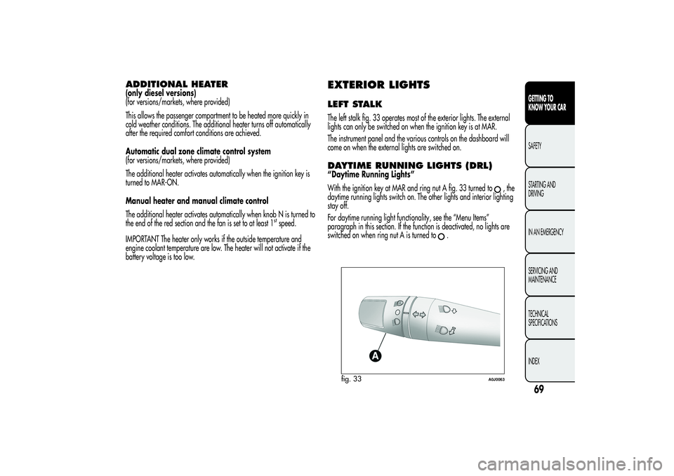
EXTERIOR LIGHTSLEFT STALKThe left stalk fig. 33 operates most of the exterior lights. The external
lights can only be switched on when the ignition key is at MAR.
The instrument panel and the various controls on the dashboard will
come on when the external lights are switched on.DAYTIME RUNNING LIGHTS (DRL)“Daytime Running Lights”
With the ignition key at MAR and ring nut A fig. 33 turned to
,the
daytime running lights switch on. The other lights and interior lighting
stay off.
For daytime running light functionality, see the “Menu Items”
paragraph in this section. If the function is deactivated, no lights are
switched on when ring nut A is turned to
.
fig. 33
A0J0063
69GETTING TO
KNOW YOUR CARSAFETY
STARTING AND
DRIVING
IN AN EMERGENCY
SERVICING AND
MAINTENANCE
TECHNICAL
SPECIFICATIONS
INDEX
Page 78 of 312

The sensitivity of the rain sensor can be adjusted through the Set-up
menu (see paragraph “Menu Items” in this section).
If the engine is stopped with the lever in “automatic” position, when it
is next started no wiping cycle will take place even if it is raining.
This prevents accidental activation of the rain sensor when the engine
is started (e.g. when the windscreen is being washed by hand or
the wipers are stuck to the windscreen when there is ice).
Carry out any of the following manoeuvres to restore automatic
operation of the system:
❒movement of left stalk from the automatic position to any other
position and then back to automatic;
❒sensitivity adjustment (by turning ring nut A to increase or decrease).
When the rain sensor is reactivated using any of the manoeuvres
described above, reactivation is indicated by a single stroke of the
windscreen wipers, regardless of the condition of the windscreen.
If the sensitivity is changed whilst the rain sensor is operating, a
windscreen wiper stroke is carried out to confirm the change.
In the event of malfunction of the rain sensor whilst it is active, the
windscreen wiper operates intermittently at a speed consistent with the
sensitivity setting of the rain sensor, regardless of whether there is
rain on the glass (sensor failure is indicated on the display).
The sensor continues to operate and it is possible to set the windscreen
wiper to continuous mode (1
stor 2
ndspeed). The failure indication
remains for as long as the sensor is active.
REAR WINDOW WASHER/WIPER(for versions/markets, where provided)
Activation
This operates only with the ignition key turned to MAR.
Turn ring nut B fig. 34 from positionOto position
to operate the
rear window wiper as follows:
❒in intermittent mode when the windscreen wiper is not operating;
❒in synchronous mode (at half the speed of the windscreen wiper)
when the windscreen wiper is operating;
❒in continuous mode with reverse gear engaged and the control
active.
With reverse gear engaged and windscreen wiper on, the rear
window wiper is activated in continuous mode. Pushing the stalk
towards the dashboard (unstable position) will activate the rear
window washer jet.
Keep the stalk pushed for more than half a second to activate the rear
window wiper as well. Releasing the stalk will activate the smart
washing function, as described for the windscreen wiper.
74GETTING TO
KNOW YOUR CAR
SAFETY
STARTING AND
DRIVING
IN AN EMERGENCY
SERVICING AND
MAINTENANCE
TECHNICAL
SPECIFICATIONS
INDEX
Page 119 of 312
WIRING FOR RADIO SYSTEM(for versions/markets, where provided)
If no radio was requested with the car, it is provided with a dual
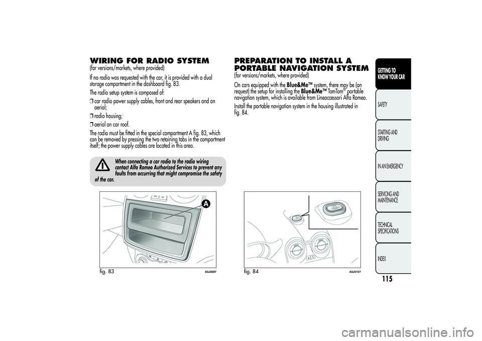
storage compartment in the dashboard fig. 83.
The radio setup system is composed of:
❒car radio power supply cables, front and rear speakers and an
aerial;
❒radio housing;
❒aerial on car roof.
The radio must be fitted in the special compartment A fig. 83, which
can be removed by pressing the two retaining tabs in the compartment
itself; the power supply cables are located in this area.
When connecting a car radio to the radio wiring
contact Alfa Romeo Authorized Services to prevent any
faults from occurring that might compromise the safety
of the car.
PREPARATION TO INSTALL A
PORTABLE NAVIGATION SYSTEM(for versions/markets, where provided)
On cars equipped with theBlue&Me™system, there may be (on
request) the setup for installing theBlue&Me™TomTom
®portable
navigation system, which is available from Lineaccessori Alfa Romeo.
Install the portable navigation system in the housing illustrated in
fig. 84.
fig. 83
A0J0087
fig. 84
A0J0107
115GETTING TO
KNOW YOUR CARSAFETY
STARTING AND
DRIVING
IN AN EMERGENCY
SERVICING AND
MAINTENANCE
TECHNICAL
SPECIFICATIONS
INDEX
Page 134 of 312
CARRYING CHILDREN SAFELYFor optimal protection in the event of a collision, all passengers must
be seated and wearing adequate restraint systems. This is even more
important for children.
This prescription is compulsory in all EC countries according to EC
Directive 2003/20/EC. Compared with adults, a child's head is
proportionally larger and heavier than the rest of the body, while
muscles and bone structure are not fully developed. Therefore, correct
restraint systems are necessary which are different from adult seat
belts.
Over 1.50 m in height, from the point of view of restraint systems,
children are considered as adults and wear the seat belts normally.
The results of research in relation to the best protection for children is
summarised in European Regulation EEC-R44, which divides the
restraint systems into five groups in addition to making their use
compulsory:Group Weight groups
Group0 upto10kg
Group 0+ up to 13 kg
Group 1 9-18 kg
Group 2 15-25 kg
Group 3 22-36 kgAll restraint devices must bear the type-approval data along with the
control mark on a label firmly secured to the child seat which must
never be removed.Lineaccessori Alfa Romeo includes child seats for each weight group.
These devices are recommended having been specifically tested for
Alfa Romeo cars.
Do not arrange cradle child seats facing backwards if
the front passenger side airbag is enabled.
Deployment of the airbag in an accident could cause
fatal injuries to the baby regardless of the severity of the
collision. It is advisable to always carry children in a child seat on
the rear seat, which is the most protected position in the event
of a collision.Should it be absolutely necessary to carry a child on the
front seat in a backwards-facing cradle seat, the
passenger's front and side air bags must be deactivated
through the Setup menu. Deactivation should be verified by
checking the
warning light on the instrument panel.
The passenger seat must also be slid back as far as possible in order
to avoid the child seat from coming into contact with the dashboard.
130GETTING TO KNOW
YOUR CAR
SAFETY
STARTING AND
DRIVING
IN AN EMERGENCY
SERVICING AND
MAINTENANCE
TECHNICAL
SPECIFICATIONS
INDEX
Page 141 of 312
FRONT AIRBAGSThe car is equipped with multi-stage front airbags (“Smart bags”) for
the driver and passenger and knee bags for the driver.“SMART BAG” SYSTEM (MULTISTAGE
FRONT AIRBAGS)The front airbags (driver's and passenger's) and the driver's knee bag
have been designed to protect the occupants in the event of head-on
crashes of medium-high severity, by placing cushions between the
occupant and the steering wheel or dashboard.
Therefore non-deployment in other types of impacts (side impacts, rear
shunts, roll-overs, etc.) does not indicate a system malfunction.Front airbags may not activate in the following situations:
❒frontal impacts against highly deformable objects not involving the
front surface of the car (e.g. wing collision against guard rail);
❒jamming of the car underneath other vehicles or protective barriers
(e.g. underneath a truck or a guard rail); in this case, the bags
would offer no additional protection with respect to the seat belt and
their deployment would be inappropriate. In these cases, non-
deployment does not indicate a system malfunction.
Do not apply stickers or other objects to the steering
wheel, to the passenger's side air bag cover or on the
roof side lining. Do not place objects on the passenger
side of the dashboard because these could interfere with the
correct opening of the passenger airbag and cause injury to
occupants.
137GETTING TO KNOW
YOUR CARSAFETYSTARTING AND
DRIVING
IN AN EMERGENCY
SERVICING AND
MAINTENANCE
TECHNICAL
SPECIFICATIONS
INDEX
The airbags do not replace, but rather complement, the use of seat
belts, which should always be worn. In the event of an impact,
someone not wearing a seat belt could move forward and come into
contact with a bag which is still in the opening phase. The protection
offered by the bag is compromised in these circumstances.
Page 142 of 312
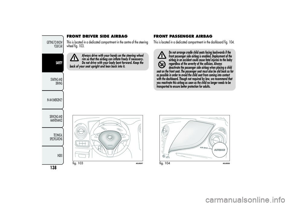
FRONT DRIVER SIDE AIRBAGThis is located in a dedicated compartment in the centre of the steering
wheel fig. 103.
Always drive with your hands on the steering wheel
rim so that the airbag can inflate freely if necessary.
Do not drive with your body bent forward. Keep the
back of your seat upright and lean back into it.
FRONT PASSENGER AIRBAGThis is located in a dedicated compartment in the dashboard fig. 104.
Do not arrange cradle child seats facing backwards if the
front passenger side airbag is enabled. Deployment of the
airbag in an accident could cause fatal injuries to the baby
regardless of the severity of the collision. Always
deactivate the passenger side airbag when placing a child
seat on the front seat. The passenger seat must also be slid back as far
as possible in order to avoid the child seat from coming into contact
with the dashboard. Though not required by law, we recommend that
you reactivate this airbag as soon as the child no longer needs to be
transported to ensure better protection for adults.
fig. 103
A0J0047
fig. 104
A0J0050
138GETTING TO KNOW
YOUR CAR
SAFETY
STARTING AND
DRIVING
IN AN EMERGENCY
SERVICING AND
MAINTENANCE
TECHNICAL
SPECIFICATIONS
INDEX
Page 165 of 312
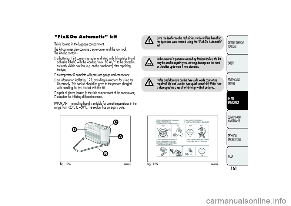
"Fix&Go Automatic" kitThis is located in the luggage compartment.
The kit container also contains a screwdriver and the tow hook.
The kit also contains:
❒a bottle fig. 124 containing sealer and fitted with: filling tube B and
adhesive label C with the wording “max. 80 km/h” to be placed in
a clearly visible position (e.g. on the dashboard) after repairing
the tyre;
❒a compressor D complete with pressure gauge and connectors;
❒an information leaflet fig. 125, providing instructions for using the
kit correctly. This booklet should be given to the persons charged
with handling the tyre treated with this kit;
❒a pair of gloves located in the side compartment of the compressor;
❒adapters for inflating different elements.
IMPORTANT The sealing liquid is suitable for use at temperatures in the
range from –20°C to +50°C. The sealant has an expiry date.
Give the leaflet to the technicians who will be handling
the tyre that was treated using the "Fix&Go Automatic"
kit.In the event of a puncture caused by foreign bodies, the kit
may be used to repair tyres showing damage on the track
or shoulder up to max 4 mm diameter.Holes and damage on the tyre side walls cannot be
repaired. Do not use the tyre quick repair kit if the tyre
is damaged as a result of driving with it deflated.
fig. 124
A0J0112
fig. 125
A0J0113
161GETTING TO KNOW
YOUR CAR
SAFETY
STARTING AND
DRIVINGIN AN
EMERGENCYSERVICING AND
MAINTENANCE
TECHNICAL
SPECIFICATIONS
INDEX