ALFA ROMEO STELVIO 2021 Owner's Guide
Manufacturer: ALFA ROMEO, Model Year: 2021, Model line: STELVIO, Model: ALFA ROMEO STELVIO 2021Pages: 280, PDF Size: 10.02 MB
Page 31 of 280
29
To unlock the steering column, push the tilt/
telescoping control handle down to the open
position. To tilt the steering column, move the
steering wheel upward or downward as
desired. To lengthen or shorten the steering
column, pull the steering wheel outward or
push it inward as desired. To lock the steering
column in position, push the tilt/telescoping
control handle to the closed position.
Heated Steering Wheel — If Equipped
The steering wheel contains a heating element
that helps warm your hands in cold weather.
The heated steering wheel has only one
temperature setting. The heated steering
wheel may not turn on when it is already warm.
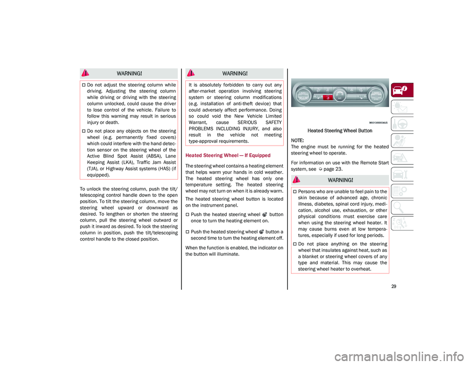
The heated steering wheel button is located
on the instrument panel.
Push the heated steering wheel button
once to turn the heating element on.
Push the heated steering wheel button a
second time to turn the heating element off.
When the function is enabled, the indicator on
the button will illuminate. Heated Steering Wheel Button
NOTE:
The engine must be running for the heated
steering wheel to operate.
For information on use with the Remote Start
system, see
Ú
page 23.
WARNING!
Do not adjust the steering column while
driving. Adjusting the steering column
while driving or driving with the steering
column unlocked, could cause the driver
to lose control of the vehicle. Failure to
follow this warning may result in serious
injury or death.
Do not place any objects on the steering
wheel (e.g. permanently fixed covers)
which could interfere with the hand detec -
tion sensor on the steering wheel of the
Active Blind Spot Assist (ABSA), Lane
Keeping Assist (LKA), Traffic Jam Assist
(TJA), or Highway Assist systems (HAS) (if
equipped).
WARNING!
It is absolutely forbidden to carry out any
after-market operation involving steering
system or steering column modifications
(e.g. installation of anti-theft device) that
could adversely affect performance. Doing
so could void the New Vehicle Limited
Warrant, cause SERIOUS SAFETY
PROBLEMS INCLUDING INJURY, and also
result in the vehicle not meeting
type-approval requirements.
WARNING!
Persons who are unable to feel pain to the
skin because of advanced age, chronic
illness, diabetes, spinal cord injury, medi -
cation, alcohol use, exhaustion, or other
physical conditions must exercise care
when using the steering wheel heater. It
may cause burns even at low tempera -
tures, especially if used for long periods.
Do not place anything on the steering
wheel that insulates against heat, such as
a blanket or steering wheel covers of any
type and material. This may cause the
steering wheel heater to overheat.
21_GU_OM_EN_USC_t.book Page 29
Page 32 of 280
GETTING TO KNOW YOUR VEHICLE
30
DRIVER MEMORY SETTINGS — IF
EQUIPPED
This feature allows the driver to store up to
three different memory profiles for easy recall
through a memory switch. Each memory
profile saves desired position settings for the
following features:
Driver seat
Side mirrors
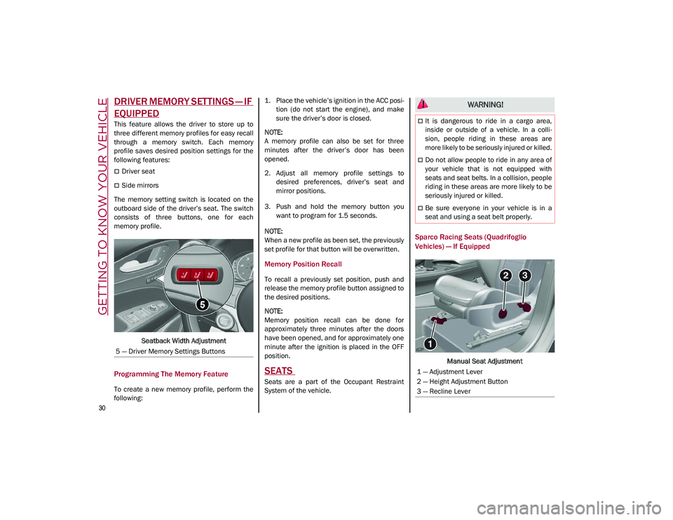
The memory setting switch is located on the
outboard side of the driver’s seat. The switch
consists of three buttons, one for each
memory profile.
Seatback Width Adjustment
Programming The Memory Feature
To create a new memory profile, perform the
following: 1. Place the vehicle’s ignition in the ACC posi
-
tion (do not start the engine), and make
sure the driver’s door is closed.
NOTE:
A memory profile can also be set for three
minutes after the driver’s door has been
opened.
2. Adjust all memory profile settings to desired preferences, driver’s seat and
mirror positions.
3. Push and hold the memory button you want to program for 1.5 seconds.
NOTE:
When a new profile as been set, the previously
set profile for that button will be overwritten.
Memory Position Recall
To recall a previously set position, push and
release the memory profile button assigned to
the desired positions.
NOTE:
Memory position recall can be done for
approximately three minutes after the doors
have been opened, and for approximately one
minute after the ignition is placed in the OFF
position.
SEATS
Seats are a part of the Occupant Restraint
System of the vehicle.
Sparco Racing Seats (Quadrifoglio
Vehicles) — If Equipped
Manual Seat Adjustment
5 — Driver Memory Settings Buttons
WARNING!
It is dangerous to ride in a cargo area,
inside or outside of a vehicle. In a colli
-
sion, people riding in these areas are
more likely to be seriously injured or killed.
Do not allow people to ride in any area of
your vehicle that is not equipped with
seats and seat belts. In a collision, people
riding in these areas are more likely to be
seriously injured or killed.
Be sure everyone in your vehicle is in a
seat and using a seat belt properly.
1 — Adjustment Lever
2 — Height Adjustment Button
3 — Recline Lever
21_GU_OM_EN_USC_t.book Page 30
Page 33 of 280
31
(Continued)
Adjusting The Seat Forward Or Rearward
The adjustment lever is at the front of the seat,
near the floor. Pull the bar upward to move the
seat forward or rearward. Release the bar
once the seat is in the desired position. Using
body pressure, move forward and rearward on
the seat to be sure that the seat adjusters
have latched.
Adjusting The Seat Up Or Down
Push the height adjustment button upward or
downward to obtain your desired height.
Reclining The Seatback
To adjust the seatback, lift the recline lever
located on the outboard side of the seat, lean
back to the desired position and release the
lever. To return the seatback, lift the lever,
lean forward and release the lever.
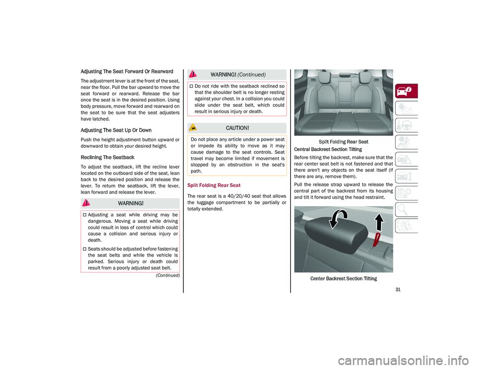
Split Folding Rear Seat
The rear seat is a 40/20/40 seat that allows
the luggage compartment to be partially or
totally extended.Split Folding Rear Seat
Central Backrest Section Tilting
Before tilting the backrest, make sure that the
rear center seat belt is not fastened and that
there aren't any objects on the seat itself (if
there are any, remove them).
Pull the release strap upward to release the
central part of the backrest from its housing
and tilt it forward using the head restraint.
Center Backrest Section Tilting
WARNING!
Adjusting a seat while driving may be
dangerous. Moving a seat while driving
could result in loss of control which could
cause a collision and serious injury or
death.
Seats should be adjusted before fastening
the seat belts and while the vehicle is
parked. Serious injury or death could
result from a poorly adjusted seat belt.
Do not ride with the seatback reclined so
that the shoulder belt is no longer resting
against your chest. In a collision you could
slide under the seat belt, which could
result in serious injury or death.
CAUTION!
Do not place any article under a power seat
or impede its ability to move as it may
cause damage to the seat controls. Seat
travel may become limited if movement is
stopped by an obstruction in the seat's
path.
WARNING! (Continued)
21_GU_OM_EN_USC_t.book Page 31
Page 34 of 280
GETTING TO KNOW YOUR VEHICLE
32
Central Backrest Section Repositioning
Using the head restraint, lift the central portion
upwards, manually guiding it back into place.
Lightly push to make sure that it is properly
latched. Make sure that the armrest is prop-
erly latched by gently trying to move it. If it is
not latched, repeat the operation.
Repositioning The Backrests
Move the seat belts to the side, making sure
that they are correctly extended and not
twisted. Also make sure that they are not
caught on anything behind the backrests of
the seats. Then, lift the backrests by pushing
them rearward until you hear the lock click into
place on both attachment mechanisms.
Extending The Luggage Compartment
The rear seatbacks can be folded forward to
provide an additional storage area.
Extending the right side of the luggage
compartment allows you to carry two passen -
gers on the left part of the rear seat, while
extending the left side allows you to carry one
passenger. Proceed as follows:
1. Completely lower the rear seat head
restraints
Ú
page 35.
2. Place the seat belt so that it doesn't impede the movement of the backrest
while tilting it.
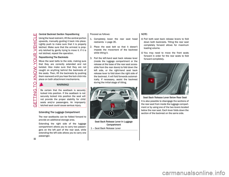
3. Pull the left-hand seat back release lever (inside the luggage compartment or the
release at the base of the rear seat acces -
sible from the rear doors) to fold down the
left side, or the right-hand seat back
release lever to fold down the right side of
the backrest. It will fold forwards automat-
ically. If necessary, assist the backrest
during the initial stage of tilting.
Seat Back Release Lever In Luggage Compartment
NOTE:
Pull both seat back release levers to fold
down both backrests. Tilting the rear seat
completely forward allows for maximum
loading volume.
You may need to move the front seats
forward in order for the rear seats to fold
forward completely.
Seat Back Release Lever Below Rear Seat
It is also possible to disengage the sections of
the rear seat from inside the luggage compart -
ment or by using one of the two levers located
below the rear seat. Each lever folds down the
section of the backrest on the same side.
WARNING!
Be certain that the seatback is securely
locked into position. If the seatback is not
securely locked into position the seat will
not provide the proper stability for child
seats and/or passengers. An improperly
latched seat could cause serious injury.
1 — Seat Back Release Lever
21_GU_OM_EN_USC_t.book Page 32
Page 35 of 280
33
Power Adjustment (Front Seats)
NOTE:
The seat layout may vary according to the
vehicle options.
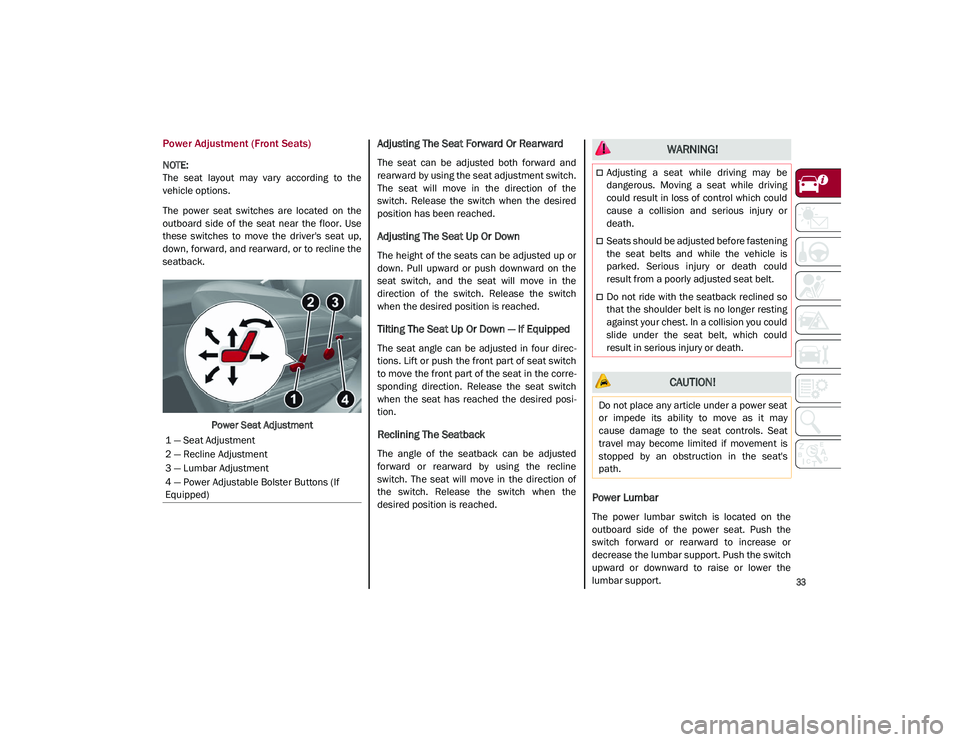
The power seat switches are located on the
outboard side of the seat near the floor. Use
these switches to move the driver's seat up,
down, forward, and rearward, or to recline the
seatback.Power Seat Adjustment
Adjusting The Seat Forward Or Rearward
The seat can be adjusted both forward and
rearward by using the seat adjustment switch.
The seat will move in the direction of the
switch. Release the switch when the desired
position has been reached.
Adjusting The Seat Up Or Down
The height of the seats can be adjusted up or
down. Pull upward or push downward on the
seat switch, and the seat will move in the
direction of the switch. Release the switch
when the desired position is reached.
Tilting The Seat Up Or Down — If Equipped
The seat angle can be adjusted in four direc -
tions. Lift or push the front part of seat switch
to move the front part of the seat in the corre -
sponding direction. Release the seat switch
when the seat has reached the desired posi -
tion.
Reclining The Seatback
The angle of the seatback can be adjusted
forward or rearward by using the recline
switch. The seat will move in the direction of
the switch. Release the switch when the
desired position is reached.
Power Lumbar
The power lumbar switch is located on the
outboard side of the power seat. Push the
switch forward or rearward to increase or
decrease the lumbar support. Push the switch
upward or downward to raise or lower the
lumbar support.
1 — Seat Adjustment
2 — Recline Adjustment
3 — Lumbar Adjustment
4 — Power Adjustable Bolster Buttons (If
Equipped)
WARNING!
Adjusting a seat while driving may be
dangerous. Moving a seat while driving
could result in loss of control which could
cause a collision and serious injury or
death.
Seats should be adjusted before fastening
the seat belts and while the vehicle is
parked. Serious injury or death could
result from a poorly adjusted seat belt.
Do not ride with the seatback reclined so
that the shoulder belt is no longer resting
against your chest. In a collision you could
slide under the seat belt, which could
result in serious injury or death.
CAUTION!
Do not place any article under a power seat
or impede its ability to move as it may
cause damage to the seat controls. Seat
travel may become limited if movement is
stopped by an obstruction in the seat's
path.
21_GU_OM_EN_USC_t.book Page 33
Page 36 of 280

GETTING TO KNOW YOUR VEHICLE
34
Seat Cushion Extension — If Equipped
Lift the adjustment lever and push the front of
the cushion forward or rearward to extend the
cushion by a few inches (centimeters).Seat Cushion Extension
Power Bolster Adjustment — If Equipped
Push the power bolster adjustment buttons to
regulate the width of the backrest through the
lateral padding.
Easy Entry Function
The Easy Entry function is designed to move
the driver side seat forward automatically by
2.36 inches (60 mm) to make it easier for the
driver to get in and out of the car.
The movement is activated only if the seat is
set to a driving position which is in front of the
B-pillar of the vehicle. The function is associated with power driver
seats for each of the three stored positions.
The Easy Entry function can be activated/
deactivated through the radio system. Refer to
the Information and Entertainment System
Owner’s Manual Supplement for further infor
-
mation.
Heated Seats — If Equipped
For information on use with the Remote Start
system, see
Ú
page 23.
Front Heated Seats — If Equipped
NOTE:
Quadrifoglio vehicles equipped with Sparco
Racing Seats will not be equipped with the
heated seat feature.
A push of the heated seat buttons located on
the instrument panel, near the climate
controls, will select the heat levels in order of
highest to lowest. A fourth push of the button
will turn the heated seat off.
NOTE:
The heated seat function can also be activated
through the radio system. Refer to the Infor -
mation and Entertainment System Owner’s
Manual Supplement for further information.
You can select three heating levels:
Maximum — three LED indicators illumi -
nated on the buttons
Average — two LED indicators illuminated
on the buttons
Minimum — one LED indicator illuminated
on the buttons
Heated Seat Buttons
6 — Adjustment Lever
WARNING!
Persons who are unable to feel pain to the
skin because of advanced age, chronic
illness, diabetes, spinal cord injury, medi
-
cation, alcohol use, exhaustion or other
physical condition must exercise care
when using the seat heater. It may cause
burns even at low temperatures, espe -
cially if used for long periods of time.
Do not place anything on the seat or seat -
back that insulates against heat, such as
a blanket or cushion. This may cause the
seat heater to overheat. Sitting in a seat
that has been overheated could cause
serious burns due to the increased
surface temperature of the seat.
21_GU_OM_EN_USC_t.book Page 34
Page 37 of 280
35
NOTE:
After selecting a heating level, heat will be
felt within a few minutes.
The engine must be running for the heated
seats to operate.
The “minimum” setting is automatically
deactivated once a certain period of time
has elapsed.
Rear Heated Seats — If Equipped
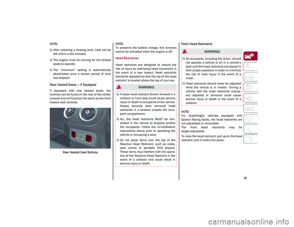
If equipped with rear heated seats, the
controls can be found on the rear of the center
console and will function the same as the front
heated seat controls.Rear Heated Seat Buttons
NOTE:
To preserve the battery charge, this function
cannot be activated when the engine is off.
Head Restraints
Head restraints are designed to reduce the
risk of injury by restricting head movement in
the event of a rear impact. Head restraints
should be adjusted so that the top of the head
restraint is located above the top of your ear.
Front Head Restraints
NOTE:
For Quadrifoglio vehicles equipped with
Sparco Racing Seats, the head restraints are
not adjustable or removable.
The front head restraints may be
height-adjustable.
To raise the head restraint, pull up on the head
restraint until it clicks into place.
WARNING!
A loose head restraint thrown forward in a
collision or hard stop could cause serious
injury or death to occupants of the vehicle.
Always securely stow removed head
restraints in a location outside the occu
-
pant compartment.
ALL the head restraints MUST be rein -
stalled in the vehicle to properly protect
the occupants. Follow the re-installation
instructions above prior to operating the
vehicle or occupying a seat.
Do not place items over the top of the
Reactive Head Restraint, such as coats,
seat covers or portable DVD players.
These items may interfere with the opera -
tion of the Reactive Head Restraint in the
event of a collision and could result in
serious injury or death.
WARNING!
All occupants, including the driver, should
not operate a vehicle or sit in a vehicle’s
seat until the head restraints are placed in
their proper positions in order to minimize
the risk of neck injury in the event of a
crash.
Head restraints should never be adjusted
while the vehicle is in motion. Driving a
vehicle with the head restraints improp -
erly adjusted or removed could cause
serious injury or death in the event of a
collision.
21_GU_OM_EN_USC_t.book Page 35
Page 38 of 280
GETTING TO KNOW YOUR VEHICLE
36
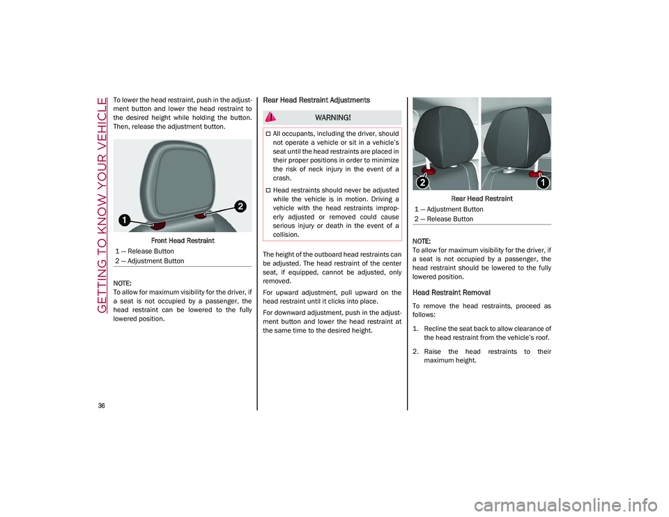
To lower the head restraint, push in the adjust-
ment button and lower the head restraint to
the desired height while holding the button.
Then, release the adjustment button.
Front Head Restraint
NOTE:
To allow for maximum visibility for the driver, if
a seat is not occupied by a passenger, the
head restraint can be lowered to the fully
lowered position.Rear Head Restraint Adjustments
The height of the outboard head restraints can
be adjusted. The head restraint of the center
seat, if equipped, cannot be adjusted, only
removed.
For upward adjustment, pull upward on the
head restraint until it clicks into place.
For downward adjustment, push in the adjust -
ment button and lower the head restraint at
the same time to the desired height. Rear Head Restraint
NOTE:
To allow for maximum visibility for the driver, if
a seat is not occupied by a passenger, the
head restraint should be lowered to the fully
lowered position.
Head Restraint Removal
To remove the head restraints, proceed as
follows:
1. Recline the seat back to allow clearance of the head restraint from the vehicle’s roof.
2. Raise the head restraints to their maximum height.
1 — Release Button
2 — Adjustment Button
WARNING!
All occupants, including the driver, should
not operate a vehicle or sit in a vehicle’s
seat until the head restraints are placed in
their proper positions in order to minimize
the risk of neck injury in the event of a
crash.
Head restraints should never be adjusted
while the vehicle is in motion. Driving a
vehicle with the head restraints improp
-
erly adjusted or removed could cause
serious injury or death in the event of a
collision.
1 — Adjustment Button
2 — Release Button
21_GU_OM_EN_USC_t.book Page 36
Page 39 of 280
37
3. Push the adjustment button and therelease button at the side of the two
supports at the same time.
4. Pull upward on the head restraint to fully remove it.
To reinstall the head restraints, proceed as
follows:
1. Hold down both the adjustment button and release button while placing the head
restraint posts into the holes.
2. Then, reposition the head restraint to the appropriate height for the passengers.
3. Replace the seat back to the appropriate position for passengers.MIRRORS
Automatic Dimming Mirror
The rearview mirror can be adjusted up, down,
left, and right. The mirror should be adjusted
to center on the view through the rear window.
This mirror automatically adjusts for headlight
glare from vehicles behind you.
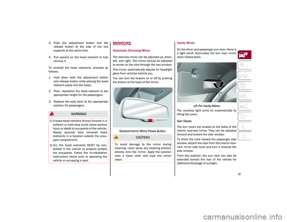
You can turn the feature on or off by pushing
the button at the base of the mirror.
Electrochromic Mirror Power Button
Vanity Mirror
On the driver and passenger sun visor, there is
a light which illuminates the sun visor mirror
when folded down. Lift For Vanity Mirror
The courtesy light turns on automatically by
lifting the cover.
Sun Visors
The sun visors are located at the sides of the
interior rearview mirror. They can be adjusted
forward and toward the side window.
To direct the visor toward the passenger side
window, detach the visor from the interior rear -
view mirror side hook and turn it towards the
side window.
From this position, the sun visor can also be
extended toward the rear of the vehicle for
additional blockage of sunlight.
WARNING!
A loose head restraint thrown forward in a
collision or hard stop could cause serious
injury or death to occupants of the vehicle.
Always securely stow removed head
restraints in a location outside the occu -
pant compartment.
ALL the head restraints MUST be rein -
stalled in the vehicle to properly protect
the occupants. Follow the re-installation
instructions above prior to operating the
vehicle or occupying a seat.
CAUTION!
To avoid damage to the mirror during
cleaning, never spray any cleaning solution
directly onto the mirror. Apply the solution
onto a clean cloth and wipe the mirror
clean.
21_GU_OM_EN_USC_t.book Page 37
Page 40 of 280
GETTING TO KNOW YOUR VEHICLE
38
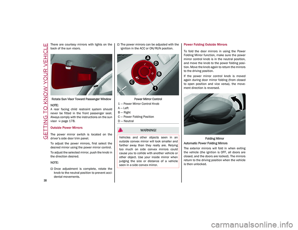
There are courtesy mirrors with lights on the
back of the sun visors.Rotate Sun Visor Toward Passenger Window
NOTE:
A rear facing child restraint system should
never be fitted in the front passenger seat.
Always comply with the instructions on the sun
visor
Ú
page 178.
Outside Power Mirrors
The power mirror switch is located on the
driver’s side door trim panel.
To adjust the power mirrors, first select the
desired mirror using the power mirror control.
To adjust the selected mirror, push the knob in
the direction desired.
NOTE:
Once adjustment is complete, rotate the
knob to the neutral position to prevent acci -
dental movements.
The power mirrors can be adjusted with the
ignition in the ACC or ON/RUN position.
Power Mirror ControlPower Folding Outside Mirrors
To fold the door mirrors in using the Power
Folding Mirror function, make sure the power
mirror control knob is in the neutral position,
and move the knob to the power folding posi -
tion. Move the knob again to return the mirrors
to the driving position.
If the power mirror control knob is moved
again during door mirror folding (from closed
to open position and vice versa), the move -
ment direction is reversed.
Folding Mirror
Automatic Power Folding Mirrors
The exterior mirrors will fold in when exiting
the vehicle (the ignition is OFF, all doors are
closed, and the doors are locked). The mirrors
return to the driving position when the vehicle
is then unlocked.
1 — Power Mirror Control Knob
A — Left
B — Right
C — Power Folding Position
D — Neutral
WARNING!
Vehicles and other objects seen in an
outside convex mirror will look smaller and
farther away than they really are. Relying
too much on side convex mirrors could
cause you to collide with another vehicle or
other object. Use your inside mirror when
judging the size or distance of a vehicle
seen in a side convex mirror.
21_GU_OM_EN_USC_t.book Page 38