manual radio set ALFA ROMEO STELVIO 2022 Owners Manual
[x] Cancel search | Manufacturer: ALFA ROMEO, Model Year: 2022, Model line: STELVIO, Model: ALFA ROMEO STELVIO 2022Pages: 256, PDF Size: 10.17 MB
Page 10 of 256
8
READ THIS CAREFULLY
Refueling..................................................... 2
Starting The Engine .................................... 2
Parking On Flammable Material ............... 2
Respecting The Environment .................... 2
Electrical Accessories ................................ 2
Scheduled Servicing .................................. 2
Rollover Warning ........................................ 3
VEHICLE CHANGES /
ALTERATIONS
Accessories Purchased By The Owner ...... 4
Installing Electrical/Electronic Devices .... 4
Radio Transmitters And Mobile Phones ... 4
HOW TO USE THIS MANUAL
Operating Instructions ............................... 5
Warnings And Cautions.............................. 5
Symbols Key ............................................... 6
Symbols ..................................................... 6
SYMBOL GLOSSARY .................................14
GETTING TO KNOW YOUR
VEHICLE
KEYS..........................................................19
Key Fob................................................... 19
ENGINE IMMOBILIZER SYSTEM ..............21 IGNITION SWITCH .................................... 22
Keyless Push Button Ignition ................ 22
REMOTE START — IF EQUIPPED .............. 23
How To Use Remote Start ..................... 23
To Exit Remote Start Mode ................... 23
Remote Start Comfort Systems —
If Equipped ............................................. 23
VEHICLE SECURITY
SYSTEM — IF EQUIPPED .......................... 24
To Arm The System................................ 24
To Disarm The System .......................... 24
Volumetric/Anti-Lift Protection —
If Equipped ............................................. 24
DOORS ...................................................... 25
Power Door Locks.................................. 25
Locking The Doors With A Depleted
Battery .................................................... 25 Passive Entry System ........................... 26
Power Lock Safety Device..................... 28
Automatic Door Locks — If Equipped .. 28
Child-Protection Door Lock System —
Rear Doors ............................................. 28
STEERING WHEEL.................................... 29
Manual Tilt/Telescoping Steering
Column ................................................... 29 Heated Steering Wheel —
If Equipped ............................................ 30
DRIVER MEMORY SETTINGS —
IF EQUIPPED ............................................ 30
Programming The Memory Feature ..... 30
Memory Position Recall ........................ 31
SEATS .......................................................31
Sparco Racing Seats (Quadrifoglio
Vehicles) — If Equipped .........................31 Split Folding Rear Seat ..........................32
Power Adjustment (Front Seats) ...........33
Heated Seats — If Equipped .................34
Head Restraints .....................................35
MIRRORS .................................................37
Automatic Dimming Mirror ....................37
Vanity Mirror ...........................................37
Outside Power Mirrors ...........................38
Power Folding Outside Mirrors ..............38
Outside Automatic Dimming
Mirrors — If Equipped............................. 38 Heated Mirrors .......................................38
UNIVERSAL GARAGE DOOR OPENER
(HOMELINK®)
S....................................39
Before You Begin Programming
HomeLink® ............................................39 Erasing All The HomeLink® Channels ..39
Identifying Whether You Have A
Rolling Code Or Non-Rolling Code
Device .....................................................39 Programming HomeLink® To A
Garage Door Opener ..............................40 Programming HomeLink® To A
Miscellaneous Device ............................ 40 Reprogramming A Single HomeLink®
Button .....................................................41 Canadian/Gate Operator
Programming .......................................... 41 Security ...................................................41
Troubleshooting Tips..............................41
22_GU_OM_EN_USC_t.book Page 8
Page 21 of 256
19
In this section, you will find important information
to help you become familiar with the features
needed to operate your vehicle, and how they
function.
KEYS
KEY FOB
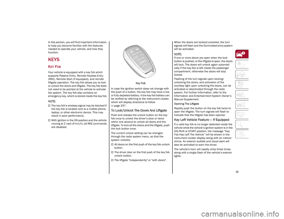
Your vehicle is equipped with a key fob which
supports Passive Entry, Remote Keyless Entry
(RKE), Remote Start (if equipped), and remote
liftgate operation. The key fob allows you to lock
or unlock the doors and liftgate. The key fob does
not need to be pointed at the vehicle to activate
the system. The key fob also contains an
emergency key, which is stored inside the key fob.
NOTE:
The key fob’s wireless signal may be blocked if
the key fob is located next to a mobile phone,
laptop, or other electronic device. This may
result in poor performance.
With ignition in the ON position and the vehicle
moving at 2 mph (4 km/h), all RKE commands
are disabled. Key Fob
In case the ignition switch does not change with
the push of a button, the key fob may have a low
or fully depleted battery. A low key fob battery can
be verified by referring to the instrument cluster,
which will display directions to follow
Ú
page 247.
To Lock/Unlock The Doors And Liftgate
Push and release the unlock button on the key
fob once to unlock the driver’s door or twice
within one second to unlock all doors and the
liftgate. To lock all the doors and the liftgate, push
the lock button once.
The current unlock setting can be changed
through the radio system menu, so that the
system unlocks:
All doors on the first push of the key fob unlock
button.
The driver door on the first push of the key fob
unlock button.
The liftgate "independently" or "with doors". When the doors are locked/unlocked, the turn
signals will flash and the illuminated entry system
will be activated.
NOTE:
If one or more doors are open when the lock
button is pushed, or the liftgate is open, the doors
will lock. The doors will unlock again automati
-
cally if the key fob is left inside the passenger
compartment, otherwise the doors will stay
locked.
Flashing of the turn signals upon locking/
unlocking the doors, and activation of the
courtesy light upon unlocking the doors, can be
activated or deactivated through the radio
system. For further information, refer to the
Information and Entertainment System Owner’s
Manual Supplement.
Opening The Liftgate
Rapidly push the button on the key fob twice to
open the liftgate. The turn signals will flash to
indicate that the liftgate has been opened.
Key Left Vehicle Feature — If Equipped
If a valid key fob is no longer detected inside the
vehicle while the vehicle’s ignition system is in the
ON/RUN or START position, the message “Key
Fob Has Left The Vehicle” will be shown in the
instrument cluster display along with an interior
chime. An exterior audible and visual alert will
also be activated to warn the driver.
The vehicle’s horn will rapidly chirp three times
along with a single flash of the vehicle’s exterior
lights.
22_GU_OM_EN_USC_t.book Page 19
Page 28 of 256
GETTING TO KNOW YOUR VEHICLE
26
2. Turn the manual release lock cylinder clock-
wise for the right door locks or counterclock -
wise for the left door locks.
3. Remove the key/screwdriver from the manual release lock.
Proceed in one of the following ways to realign
the door lock device (only when the battery
charge has been restored):
Push the lock button on the key fob
Push the unlock button on the door panel
Unlock the driver’s door lock with the
emergency key
Operate the internal door handle
NOTE:
For the rear doors, if the Child Safety Locks are
engaged, and the previously described locking
procedure is carried out, operating the internal
handle will not open the door. Instead, it will only
realign the lock release device. To open the door,
the outside handle must be used. The door
central locking/unlocking buttons are not deacti -
vated when the emergency lock is engaged.
PASSIVE ENTRY SYSTEM
The Passive Entry system is an enhancement to
the vehicle’s key fob. This feature allows you to
lock and unlock the vehicle’s door(s) and liftgate
without having to push the key fob lock or unlock
buttons.
NOTE:
Passive Entry may be programmed on/off
through the radio screen. Refer to the
Information and Entertainment System
Owner’s Manual Supplement for Passive Entry
settings.
The key fob may not be able to be detected by
the vehicle Passive Entry system if it is located
next to a mobile phone, laptop, or other
electronic device; these devices may block the
key fob’s wireless signal and prevent the
Passive Entry system from locking/unlocking
the vehicle.
If wearing gloves, or if it has been raining/
snowing on the Passive Entry door handle, the
unlock sensitivity can be affected, resulting in
a slower response time.
If the vehicle is unlocked by Passive Entry and
no door is opened within 60 seconds, the
vehicle will relock and (if equipped) will arm
the Vehicle Security system.
To Unlock From The Driver Or Passenger Side
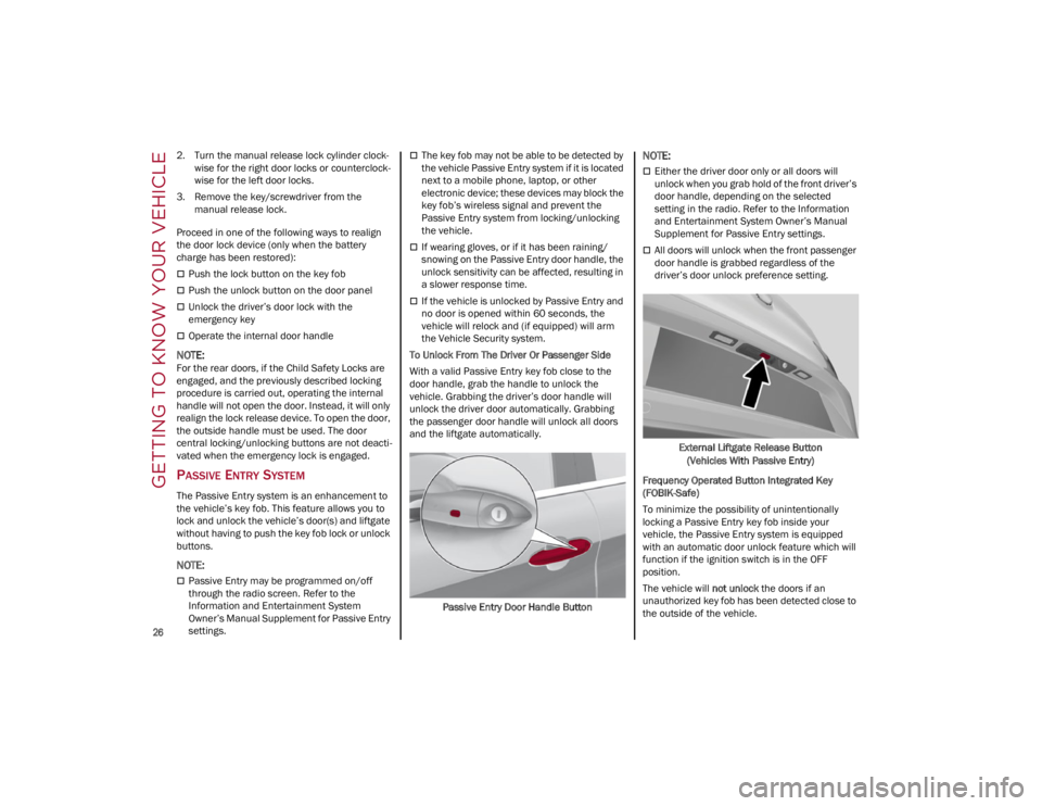
With a valid Passive Entry key fob close to the
door handle, grab the handle to unlock the
vehicle. Grabbing the driver’s door handle will
unlock the driver door automatically. Grabbing
the passenger door handle will unlock all doors
and the liftgate automatically.
Passive Entry Door Handle Button
NOTE:
Either the driver door only or all doors will
unlock when you grab hold of the front driver’s
door handle, depending on the selected
setting in the radio. Refer to the Information
and Entertainment System Owner’s Manual
Supplement for Passive Entry settings.
All doors will unlock when the front passenger
door handle is grabbed regardless of the
driver’s door unlock preference setting.External Liftgate Release Button(Vehicles With Passive Entry)
Frequency Operated Button Integrated Key
(FOBIK-Safe)
To minimize the possibility of unintentionally
locking a Passive Entry key fob inside your
vehicle, the Passive Entry system is equipped
with an automatic door unlock feature which will
function if the ignition switch is in the OFF
position.
The vehicle will not unlock the doors if an
unauthorized key fob has been detected close to
the outside of the vehicle.
22_GU_OM_EN_USC_t.book Page 26
Page 36 of 256
GETTING TO KNOW YOUR VEHICLE
34
Power Lumbar
The power lumbar switch is located on the
outboard side of the power seat. Push the switch
forward or rearward to increase or decrease the
lumbar support. Push the switch upward or
downward to raise or lower the lumbar support.
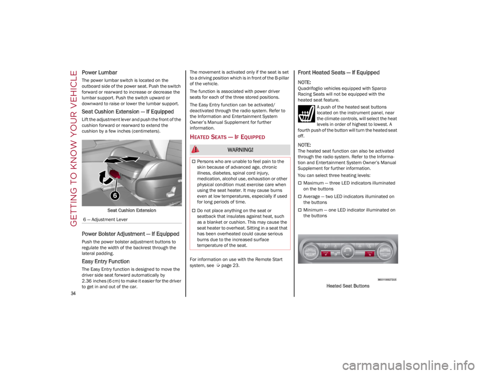
Seat Cushion Extension — If Equipped
Lift the adjustment lever and push the front of the
cushion forward or rearward to extend the
cushion by a few inches (centimeters).Seat Cushion Extension
Power Bolster Adjustment — If Equipped
Push the power bolster adjustment buttons to
regulate the width of the backrest through the
lateral padding.
Easy Entry Function
The Easy Entry function is designed to move the
driver side seat forward automatically by
2.36 inches (6 cm) to make it easier for the driver
to get in and out of the car. The movement is activated only if the seat is set
to a driving position which is in front of the B-pillar
of the vehicle.
The function is associated with power driver
seats for each of the three stored positions.
The Easy Entry function can be activated/
deactivated through the radio system. Refer to
the Information and Entertainment System
Owner’s Manual Supplement for further
information.
HEATED SEATS — IF EQUIPPED
For information on use with the Remote Start
system, see
Ú
page 23.
Front Heated Seats — If Equipped
NOTE:
Quadrifoglio vehicles equipped with Sparco
Racing Seats will not be equipped with the
heated seat feature.
A push of the heated seat buttons
located on the instrument panel, near
the climate controls, will select the heat
levels in order of highest to lowest. A
fourth push of the button will turn the heated seat
off.
NOTE:
The heated seat function can also be activated
through the radio system. Refer to the Informa -
tion and Entertainment System Owner’s Manual
Supplement for further information.
You can select three heating levels:
Maximum — three LED indicators illuminated
on the buttons
Average — two LED indicators illuminated on
the buttons
Minimum — one LED indicator illuminated on
the buttons
Heated Seat Buttons
6 — Adjustment Lever
WARNING!
Persons who are unable to feel pain to the
skin because of advanced age, chronic
illness, diabetes, spinal cord injury,
medication, alcohol use, exhaustion or other
physical condition must exercise care when
using the seat heater. It may cause burns
even at low temperatures, especially if used
for long periods of time.
Do not place anything on the seat or
seatback that insulates against heat, such
as a blanket or cushion. This may cause the
seat heater to overheat. Sitting in a seat that
has been overheated could cause serious
burns due to the increased surface
temperature of the seat.
22_GU_OM_EN_USC_t.book Page 34
Page 53 of 256
51
In automatic operation, air recirculation will be
controlled by the system according to outside
environmental conditions.
NOTE:
With the AQS function active and after the
internal air recirculation system has been
functioning for a set amount of time, the
Climate Control System enables air intake to
cycle the air in the passenger compartment for
a set time. The AQS function is disabled during
the air changes.
The engagement of the recirculation system
makes it possible to reach the required heating
or cooling conditions faster. It is, however,
inadvisable to use it on rainy/cold days as it
can increase the possibility of the windows
fogging. When the outside temperature is low,
recirculation is forced off to prevent the
windows from fogging up.
Front Defrost Air comes from the windshield and side
window demist outlets. Use Defrost
mode with maximum temperature
settings for best windshield and side
window defrosting and defogging.
Rear Defrost
Push the Rear Defrost button to activate
(indicators illuminated) the Rear
Defroster.
The Rear Defrost will turn off after 20 minutes or
once the engine is turned off.
NOTE:
To avoid damage, do not apply stickers over the
interior heating filaments of the Rear Defroster. Front Defrost And MAX-DEF Function
Push the MAX-DEF button (indicator
illuminated) to defrost the windshield
and side windows.
While in MAX-DEF function, the air conditioner
will:
Activate the air conditioner compressor when
the weather allows
Turn air recirculation off
Set the maximum air temperature (HI) on both
the driver and passenger side
Activate a blower speed based on the
temperature of the engine coolant
Adjust the air flow towards the windshield and
front side windows
Activate the Rear Window Defrost
Display the fan speed (indicators illuminated)
and current air distribution setting
NOTE:
The MAX-DEF function remains active for approx -
imately three minutes once the engine coolant
reaches the proper temperature.
When the function is on, AUTO mode will
deactivate. The only manual operations possible
are adjusting blower speed and turning off the
Rear Window Defrost.
Pushing the Air Recirculation button switches
off the MAX-DEF function.
Air Temperature Adjustment
Rotate the driver or passenger Temperature
Adjustment Knob clockwise for warmer
temperatures or counterclockwise for cooler
temperatures. The set temperatures are shown
on the radio system. Push the SYNC button to sync the driver and
passenger air temperatures.
Rotate the passenger Temperature Adjustment
Knob to cancel the SYNC function. This will set a
new passenger side temperature.
Rotate the Temperature Adjustment Knob fully
clockwise to engage the HI (maximum heating)
setting or fully counterclockwise to engage the LO
(maximum cooling) setting. To deactivate these
functions, rotate the Temperature Adjustment
Knob to the desired temperature.
Rear passengers’ temperature is linked to driver
side selection.
AUTO Button
When the AUTO button is pushed (indicator
illuminated), the Climate Control system automat
-
ically adjusts the following settings:
Quantity and distribution of air flow in the
passenger compartment
The air conditioner
Air recirculation
Cancels any manual settings
Selecting the AUTO function illuminates the
indicator on the A/C button.
If air distribution or the fan speed is manually
adjusted, the AUTO button indicator will turn off to
indicate that the Climate Control system is no
longer in AUTO mode.
After a manual adjustment, push the AUTO button
to resume the automatic system.
22_GU_OM_EN_USC_t.book Page 51
Page 63 of 256
61
Customizing The Liftgate Opening Height
To avoid difficulties in tight spaces, you can set
the height at which the liftgate opens to.
To customize the liftgate opening position, follow
the steps below:
1. Open the liftgate manually and move it to theposition that you want the liftgate to open to.
2. Press and hold one of the closing buttons for at least five seconds (successful program -
ming is indicated by the turn signals flashing
three times).
The liftgate is now programmed to open to the set
position.
This function can be selected on the radio
system.
To set the liftgate opening height, refer to the
Information and Entertainment System Owner’s
Manual Supplement for further information.
Hands-Free Liftgate — If Equipped
To operate the Hands-Free Liftgate system:
1. If the doors are locked, the system must detect the key fob near the liftgate.
2. If the doors are unlocked, the system does not have to detect the key fob near the lift -
gate.
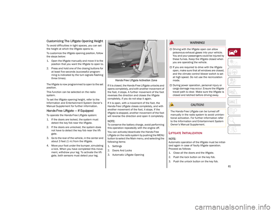
3. Go to the rear of the vehicle, in the center and about 3 feet (1 m) from the liftgate.
4. Move your foot under the bumper, simulating a kick. When you have completed this move -
ment, withdraw your leg. To activate the lift -
gate, both sensors must detect your leg. Hands Free Liftgate Activation Zone
If it is closed, the Hands-Free Liftgate unlocks and
opens completely, and with another movement of
the foot, it stops. A further movement of the foot
reverses the direction and closes the liftgate
completely, if you do not stop it again.
If it is open, with a movement of the foot, the
Hands-Free Liftgate closes completely, and with
another movement of the foot, it stops. If the
liftgate is stopped, another movement of the foot
will reverse the direction and open it completely.
NOTE:
To conserve the battery charge, avoid performing
this operation repeatedly with the engine off.
You can activate/deactivate the Hands-Free
Liftgate on the radio system by pushing the MENU
button to select the Main menu, and selecting the
following items:
1. Settings
2. Doors And Locks
3. Automatic Liftgate Opening
LIFTGATE INITIALIZATION
NOTE:
Automatic operation of the liftgate must be initial -
ized again in case of faulty liftgate operation.
Proceed as follows:
1. Close all the doors and the liftgate.
2. Push the lock button on the key fob.
3. Push the unlock button on the key fob.
WARNING!
Driving with the liftgate open can allow
poisonous exhaust gases into your vehicle.
You and your passengers could be injured by
these fumes. Keep the liftgate closed when
you are operating the vehicle.
If you are required to drive with the liftgate
open, make sure that all windows are closed,
and the climate control blower switch is set
at high speed. Do not use the recirculation
mode.
During power operation, personal injury or
cargo damage may occur. Ensure the liftgate
travel path is clear. Make sure the liftgate is
closed and latched before driving away.
CAUTION!
The Hands-Free Liftgate can be turned off
manually in the radio system to avoid uninten -
tional activation. For further information refer
to the Information and Entertainment System
Owner’s Manual Supplement.
22_GU_OM_EN_USC_t.book Page 61
Page 72 of 256
GETTING TO KNOW YOUR INSTRUMENT PANEL
70
Clock & Date
The following settings can be modified under the
“Clock & Date” menu:
Sync With GPS Time: activates or deactivates
the clock synchronization through the GPS. If
the function is deactivated, the options Set
Time and Set Date are enabled.
Set Time: set the time manually.
Time Format: set the time format to either a
12-hour or a 24-hour clock.
Set Date: set the date manually.
Restore Clock & Date Settings: restores the
factory settings.
To access and change the setting, turn and push
the Rotary Pad or press the desired setting on the
touchscreen.
Cluster
The following settings can be modified under the
“Cluster” menu:
Warning Buzzer Volume: set the volume of the
warning buzzer on seven levels.
Trip B: activate or deactivate the Trip function.
Show Phone Info: activate/deactivate
repetition of the phone function screens also
on the instrument cluster display.
Show Audio Info: activate/deactivate
repetition of the audio function screens (Radio
and Media) also on the instrument cluster
display.
Show Nav Info: activate/deactivate repetition
of the navigator function screens also on the
instrument cluster display.
Digital Speed on all screens: activate/deacti -
vating of digital speed on the instrument
cluster display screens other than the main
screen.
Consumption Bar: activate/deactivate the
consumption baron the display screens of the
instrument panel where it is available.
Performance Pages: choose, for each driving
mode, one of the two alternative contents
displayed in the screen.
Custom Areas: select which content to display
in each of the three customizable areas on the
display of the instrument panel: time, date,
outside temperature, radio information,
compass.
Restore Cluster Settings: deletes the current
settings and restores the factory settings.
To access and the change the setting, turn and
push the Rotary Pad or press the desired setting
on the touchscreen.
WARNING LIGHTS AND
MESSAGES ON THE
INSTRUMENT PANEL
The following pages consist of warning lights and
messages.
NOTE:
The warning light turns on together with a
dedicated message and/or chime when
applicable. These indications are precau -
tionary and as such must not be considered as
exhaustive and/or alternative to the
information contained in the Owner’s Manual, which you are advised to read carefully in all
cases. Always refer to the information in this
section in the event of a failure indication.
The failure indicators appearing on the display
are divided into two categories: very serious
and less serious faults. Serious faults are
indicated by a repeated and prolonged
warning cycle. Less serious faults are
indicated by a warning cycle with a shorter
duration. You can stop the warning cycle in
both cases by pushing the button located on
the windshield wiper stalk. The instrument
panel warning light will stay on until the cause
of the failure is eliminated.
RED WARNING LIGHTS
Air Bag Warning Light
This warning light will illuminate to
indicate a fault with the air bag, and will
turn on for four to eight seconds as a
bulb check when the ignition is placed
in the ON/RUN or ACC/ON/RUN position. This
light will illuminate with a single chime when a
fault with the air bag has been detected, it will
stay on until the fault is cleared. If the light is
either not on during startup, stays on, or turns on
while driving, have the system inspected at an
authorized dealer as soon as possible.
Brake Warning Light
This warning light monitors various
brake functions, including brake fluid
level and parking brake application. If
the brake light turns on it may indicate
that the parking brake is applied, that the brake
fluid level is low, or that there is a problem with
the Anti-Lock Brake System reservoir.
22_GU_OM_EN_USC_t.book Page 70
Page 101 of 256
99
To Set A Desired Speed
To set a desired speed, proceed as follows:
1. Turn the Cruise Control on.
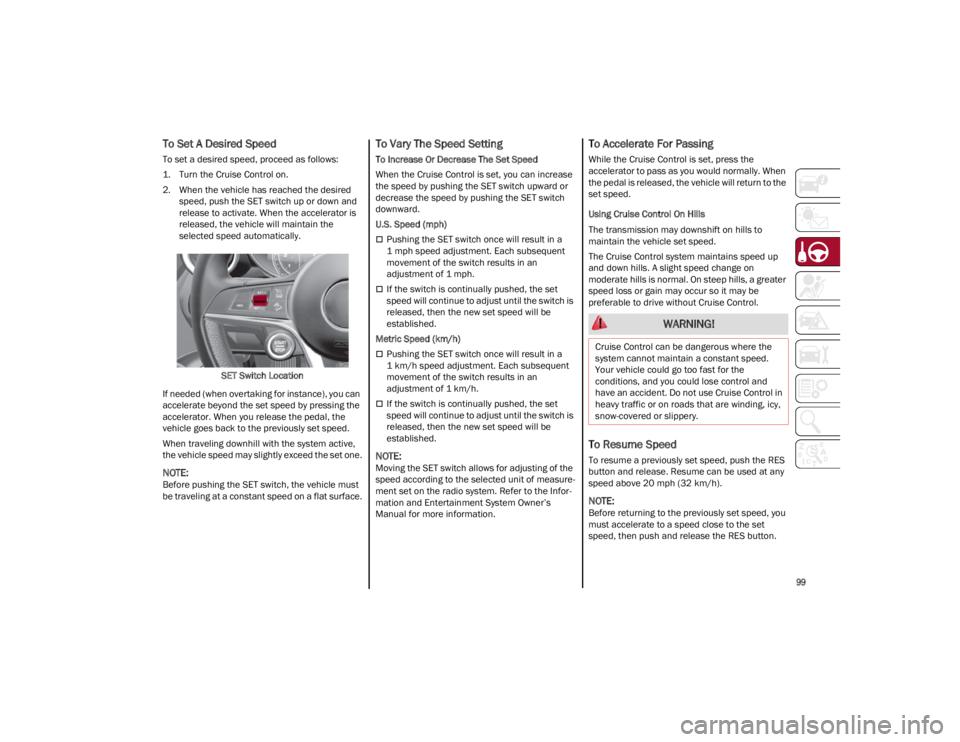
2. When the vehicle has reached the desiredspeed, push the SET switch up or down and
release to activate. When the accelerator is
released, the vehicle will maintain the
selected speed automatically.
SET Switch Location
If needed (when overtaking for instance), you can
accelerate beyond the set speed by pressing the
accelerator. When you release the pedal, the
vehicle goes back to the previously set speed.
When traveling downhill with the system active,
the vehicle speed may slightly exceed the set one.
NOTE:
Before pushing the SET switch, the vehicle must
be traveling at a constant speed on a flat surface.
To Vary The Speed Setting
To Increase Or Decrease The Set Speed
When the Cruise Control is set, you can increase
the speed by pushing the SET switch upward or
decrease the speed by pushing the SET switch
downward.
U.S. Speed (mph)
Pushing the SET switch once will result in a
1 mph speed adjustment. Each subsequent
movement of the switch results in an
adjustment of 1 mph.
If the switch is continually pushed, the set
speed will continue to adjust until the switch is
released, then the new set speed will be
established.
Metric Speed (km/h)
Pushing the SET switch once will result in a
1 km/h speed adjustment. Each subsequent
movement of the switch results in an
adjustment of 1 km/h.
If the switch is continually pushed, the set
speed will continue to adjust until the switch is
released, then the new set speed will be
established.
NOTE:
Moving the SET switch allows for adjusting of the
speed according to the selected unit of measure -
ment set on the radio system. Refer to the Infor -
mation and Entertainment System Owner’s
Manual for more information.
To Accelerate For Passing
While the Cruise Control is set, press the
accelerator to pass as you would normally. When
the pedal is released, the vehicle will return to the
set speed.
Using Cruise Control On Hills
The transmission may downshift on hills to
maintain the vehicle set speed.
The Cruise Control system maintains speed up
and down hills. A slight speed change on
moderate hills is normal. On steep hills, a greater
speed loss or gain may occur so it may be
preferable to drive without Cruise Control.
To Resume Speed
To resume a previously set speed, push the RES
button and release. Resume can be used at any
speed above 20 mph (32 km/h).
NOTE:
Before returning to the previously set speed, you
must accelerate to a speed close to the set
speed, then push and release the RES button.
WARNING!
Cruise Control can be dangerous where the
system cannot maintain a constant speed.
Your vehicle could go too fast for the
conditions, and you could lose control and
have an accident. Do not use Cruise Control in
heavy traffic or on roads that are winding, icy,
snow-covered or slippery.
22_GU_OM_EN_USC_t.book Page 99
Page 104 of 256
STARTING AND OPERATING
102
To Activate
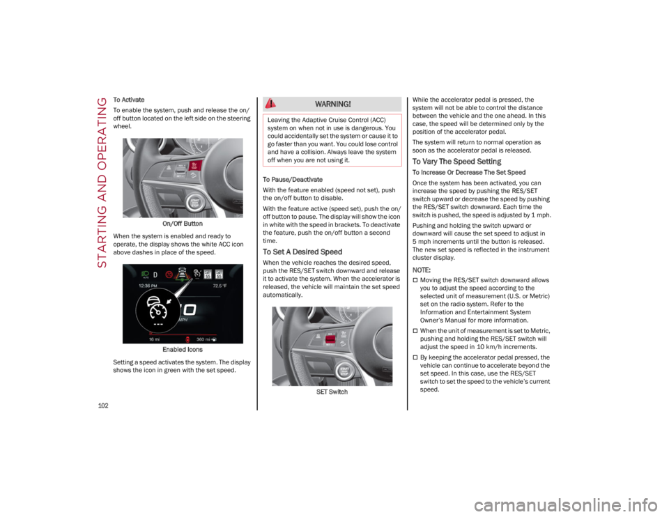
To enable the system, push and release the on/
off button located on the left side on the steering
wheel.On/Off Button
When the system is enabled and ready to
operate, the display shows the white ACC icon
above dashes in place of the speed.
Enabled Icons
Setting a speed activates the system. The display
shows the icon in green with the set speed. To Pause/Deactivate
With the feature enabled (speed not set), push
the on/off button to disable.
With the feature active (speed set), push the on/
off button to pause. The display will show the icon
in white with the speed in brackets. To deactivate
the feature, push the on/off button a second
time.
To Set A Desired Speed
When the vehicle reaches the desired speed,
push the RES/SET switch downward and release
it to activate the system. When the accelerator is
released, the vehicle will maintain the set speed
automatically.
SET Switch While the accelerator pedal is pressed, the
system will not be able to control the distance
between the vehicle and the one ahead. In this
case, the speed will be determined only by the
position of the accelerator pedal.
The system will return to normal operation as
soon as the accelerator pedal is released.
To Vary The Speed Setting
To Increase Or Decrease The Set Speed
Once the system has been activated, you can
increase the speed by pushing the RES/SET
switch upward or decrease the speed by pushing
the RES/SET switch downward. Each time the
switch is pushed, the speed is adjusted by 1 mph.
Pushing and holding the switch upward or
downward will cause the set speed to adjust in
5 mph increments until the button is released.
The new set speed is reflected in the instrument
cluster display.
NOTE:
Moving the RES/SET switch downward allows
you to adjust the speed according to the
selected unit of measurement (U.S. or Metric)
set on the radio system. Refer to the
Information and Entertainment System
Owner’s Manual for more information.
When the unit of measurement is set to Metric,
pushing and holding the RES/SET switch will
adjust the speed in 10 km/h increments.
By keeping the accelerator pedal pressed, the
vehicle can continue to accelerate beyond the
set speed. In this case, use the RES/SET
switch to set the speed to the vehicle’s current
speed.
WARNING!
Leaving the Adaptive Cruise Control (ACC)
system on when not in use is dangerous. You
could accidentally set the system or cause it to
go faster than you want. You could lose control
and have a collision. Always leave the system
off when you are not using it.
22_GU_OM_EN_USC_t.book Page 102
Page 108 of 256
STARTING AND OPERATING
106
IFETEL: RCPBOMR 14-0766
La operación de este equipo está sujeta a las
siguientes dos condiciones:
1. es posible que este equipo o dispositivo no cause interferencia perjudicial y
2. este equipo o dispositivo debe aceptar cual -
quier interferencia, incluyendo la que pueda
causar su operación no deseada.
Changes or modifications made to this
equipment not expressly approved by Robert
BOSCH GmbH may void the FCC authorization to
operate this equipment.
This equipment has been tested and found to
comply with the limits for a Class A digital device,
pursuant to Part 15 of the FCC Rules. These limits
are designed to provide reasonable protection
against harmful interference when the
equipment is operated in a commercial
environment. This equipment generates, uses,
and can radiate radio frequency energy and, if not
installed and used in accordance with the
instruction manual, may cause harmful
interference to radio communications. Operation
of this equipment in a residential area is likely to
cause harmful interference in which case the
user will be required to correct the interference at
his own expense.
Toutes modifications apportées à cet
équipement qui ne sont pas expressément
homologuées par Robert BOSCH GmbH peuvent
annuler l'autorisation de la FCC de faire
fonctionner cet équipement.
Cet appareil a été vérifié et s'est révélé conforme
aux normes applicables aux appareils
numériques de catégorie A, en vertu de la section
15 des règlements de la FCC. Ces normes sont définies pour fournir une protection raisonnable
contre les interférences nuisibles lorsque
l'équipement est utilisé dans les installations
résidentielles. Cet appareil génère, utilise et peut
émettre des ondes radioélectriques et, s'il n'est
pas installé et utilisé conformément au manuel
d’instruction, peut causer un brouillage
radioélectrique nuisible aux communications
radio. Le fonctionnement de cet équipement
dans une zone résidentielle est susceptible de
causer des interférences nuisibles; dans ce cas,
l'usager doit corriger les interférences à ses
propres frais.
Radio Frequency Exposure Information
This equipment complies with FCC radiation
exposure limits set forth for an uncontrolled
environment. This equipment should be installed
and operated with minimum distance of 20 cm
between the radiator and your body.
This transmitter must not be co-located or
operating in conjunction with any other antenna
or transmitter.
Déclaration d’exposition aux radiations
Cet équipement est conforme aux limites
d'exposition aux rayonnements IC établies pour
un environnement non contrôlé. Cet équipement
doit être installé et utilisé avec un minimum de
20 cm de distance entre la source de
rayonnement et votre corps.
Ce transmetteur ne doit pas etre place au meme
endroit ou utilise simultanement avec un autre
transmetteur ou antenne.HIGHWAY ASSIST SYSTEM
(HAS) — IF EQUIPPED
The Highway Assist System (HAS) is a driving
assistance system that is only available when
driving on highways. The system operates up to
speeds of 90 mph (145 km/h) when horizontal
signs are detected.
The system uses information from the front
camera and radar to help keep the vehicle in the
center of the lane and at a constant speed.
HAS combines Adaptive Cruise Control (ACC)
functions with lane centering logic to control the
trajectory of the vehicle. HAS requires the driver’s
hands to remain on the steering wheel.
Once HAS is activated, a dedicated screen will
appear on the instrument cluster display.
TO ACTIVATE/DEACTIVATE
To Activate
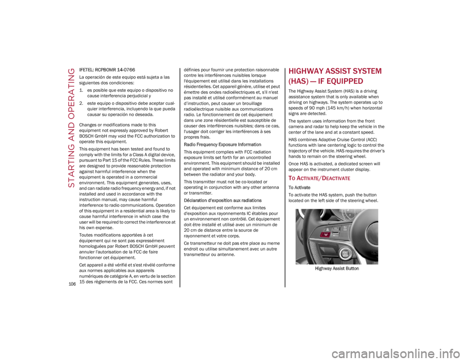
To activate the HAS system, push the button
located on the left side of the steering wheel.
Highway Assist Button
22_GU_OM_EN_USC_t.book Page 106