steering ALFA ROMEO STELVIO 2022 Owners Manual
[x] Cancel search | Manufacturer: ALFA ROMEO, Model Year: 2022, Model line: STELVIO, Model: ALFA ROMEO STELVIO 2022Pages: 256, PDF Size: 10.17 MB
Page 10 of 256
8
READ THIS CAREFULLY
Refueling..................................................... 2
Starting The Engine .................................... 2
Parking On Flammable Material ............... 2
Respecting The Environment .................... 2
Electrical Accessories ................................ 2
Scheduled Servicing .................................. 2
Rollover Warning ........................................ 3
VEHICLE CHANGES /
ALTERATIONS
Accessories Purchased By The Owner ...... 4
Installing Electrical/Electronic Devices .... 4
Radio Transmitters And Mobile Phones ... 4
HOW TO USE THIS MANUAL
Operating Instructions ............................... 5
Warnings And Cautions.............................. 5
Symbols Key ............................................... 6
Symbols ..................................................... 6
SYMBOL GLOSSARY .................................14
GETTING TO KNOW YOUR
VEHICLE
KEYS..........................................................19
Key Fob................................................... 19
ENGINE IMMOBILIZER SYSTEM ..............21 IGNITION SWITCH .................................... 22
Keyless Push Button Ignition ................ 22
REMOTE START — IF EQUIPPED .............. 23
How To Use Remote Start ..................... 23
To Exit Remote Start Mode ................... 23
Remote Start Comfort Systems —
If Equipped ............................................. 23
VEHICLE SECURITY
SYSTEM — IF EQUIPPED .......................... 24
To Arm The System................................ 24
To Disarm The System .......................... 24
Volumetric/Anti-Lift Protection —
If Equipped ............................................. 24
DOORS ...................................................... 25
Power Door Locks.................................. 25
Locking The Doors With A Depleted
Battery .................................................... 25 Passive Entry System ........................... 26
Power Lock Safety Device..................... 28
Automatic Door Locks — If Equipped .. 28
Child-Protection Door Lock System —
Rear Doors ............................................. 28
STEERING WHEEL.................................... 29
Manual Tilt/Telescoping Steering
Column ................................................... 29 Heated Steering Wheel —
If Equipped ............................................ 30
DRIVER MEMORY SETTINGS —
IF EQUIPPED ............................................ 30
Programming The Memory Feature ..... 30
Memory Position Recall ........................ 31
SEATS .......................................................31
Sparco Racing Seats (Quadrifoglio
Vehicles) — If Equipped .........................31 Split Folding Rear Seat ..........................32
Power Adjustment (Front Seats) ...........33
Heated Seats — If Equipped .................34
Head Restraints .....................................35
MIRRORS .................................................37
Automatic Dimming Mirror ....................37
Vanity Mirror ...........................................37
Outside Power Mirrors ...........................38
Power Folding Outside Mirrors ..............38
Outside Automatic Dimming
Mirrors — If Equipped............................. 38 Heated Mirrors .......................................38
UNIVERSAL GARAGE DOOR OPENER
(HOMELINK®)
S....................................39
Before You Begin Programming
HomeLink® ............................................39 Erasing All The HomeLink® Channels ..39
Identifying Whether You Have A
Rolling Code Or Non-Rolling Code
Device .....................................................39 Programming HomeLink® To A
Garage Door Opener ..............................40 Programming HomeLink® To A
Miscellaneous Device ............................ 40 Reprogramming A Single HomeLink®
Button .....................................................41 Canadian/Gate Operator
Programming .......................................... 41 Security ...................................................41
Troubleshooting Tips..............................41
22_GU_OM_EN_USC_t.book Page 8
Page 13 of 256
11
LANE KEEPING ASSIST (LKA) SYSTEM —
IF EQUIPPED .......................................... 119
Turning Lane Keeping Assist On
Or Off .................................................... 120 Lane Keeping Assist Warning
Message ...............................................120
REAR BACK UP CAMERA / DYNAMIC
GRIDLINES ............................................ 122
REFUELING THE VEHICLE ..................... 124
Refueling Capacity ............................... 124
Refueling Procedure ...........................124
VEHICLE LOADING ................................. 126
Certification Label................................ 126
TRAILER TOWING................................... 127
Common Towing Definitions ...............127
Trailer Hitch Classification .................. 128
Trailer Towing Weights (Maximum
Trailer Weight Ratings) ........................ 128 Trailer And Tongue Weight ................. 129
Towing Requirements..........................129
Towing Tips ..........................................131
Installing The Receiver ........................ 131
Connecting The Electrical System ......132
Removing The Receiver ....................... 132
SUGGESTIONS FOR DRIVING................ 132
Saving Fuel ...........................................132
Driving Style .........................................132
Conditions Of Use ................................ 133
Performance — Quadrifoglio ...............133
SAFETY
ACTIVE SAFETY SYSTEMS ..................... 135
Anti-Lock Brake System (ABS) ........... 135
Active Torque Vectoring (ATV)
System — If Equipped ......................... 135 Dynamic Steering Torque (DST)
System ................................................. 136 Drive Train Control (DTC) System....... 136
Electronic Stability Control (ESC)
System ................................................. 136 Hill Descent Control (HDC) System —
If Equipped .......................................... 137 Hill Start Assist (HSA) System ............ 138
Panic Brake Assist (PBA) System ....... 138
Traction Control System (TCS)............ 139
AUXILIARY DRIVING SYSTEMS .............. 139
Blind Spot Monitoring (BSM)
System — If Equipped ......................... 139 Active Blind Spot Assist (ABSA)
System — If Equipped ........................ 141 Driver Attention Assist (DAA)
System — If Equipped ......................... 144 Forward Collision Warning Plus
(FCW+) System — If Equipped ........... 145 Tire Pressure Monitoring System
(TPMS).................................................. 149
OCCUPANT RESTRAINT SYSTEMS ....... 151
Occupant Restraint Systems
Features .............................................. 151 Important Safety Precautions............. 151
Seat Belt Systems .............................. 152
Supplemental Restraint Systems
(SRS)..................................................... 156 Child Restraints ................................... 164
SAFETY TIPS ........................................... 173
Transporting Passengers .................... 173
Transporting Pets ................................ 173
Connected Vehicles ............................. 173
Safety Checks You Should Make
Inside The Vehicle .............................. 173 Periodic Safety Checks You Should
Make Outside The Vehicle .................. 174 Exhaust Gas ........................................ 174
Carbon Monoxide Warnings................ 175
IN CASE OF EMERGENCY
HAZARD WARNING FLASHERS ............ 176
SOS — EMERGENCY CALL ..................... 176JACKING AND TIRE CHANGING ............. 178
General Instructions............................ 179
Jack Information And Usage
Precautions .......................................... 179 Changing Procedure ............................ 179
TIRE SERVICE KIT — IF EQUIPPED ....... 181
Description ........................................... 181
Inflation Procedure .............................. 182
Checking And Restoring Tire
Pressure ............................................... 184
22_GU_OM_EN_USC_t.book Page 11
Page 14 of 256
12
JUMP STARTING ................................... 184
Remote Battery Connection Posts......184
Jump Starting Procedure.....................186
Bump Starting ..................................... 187
ENGINE OVERHEATING ......................... 187 MANUAL PARK RELEASE ...................... 188TOWING A DISABLED VEHICLE ............ 188
Four-Wheel Drive (AWD) Models .........189
TOW EYES ............................................. 189ENHANCED ACCIDENT RESPONSE
SYSTEM (EARS) .................................... 190EVENT DATA RECORDER (EDR) ............ 190
SERVICING AND MAINTENANCE
SCHEDULED SERVICING ....................... 191
Periodic Checks ...................................191
Heavy Usage Of The Vehicle ...............191
Maintenance Plan — 2.0L Engine .......192
Maintenance Plan — 2.9L Engine .......194
ENGINE COMPARTMENT....................... 196
Checking Levels — 2.0L Engine .......... 196
Checking Levels — 2.9L Engine .......... 197
Engine Oil ............................................. 197
Engine Coolant Fluid............................198
Washer Fluid For Windshield/
Headlights ............................................ 198 Brake Fluid ...........................................199
Automatic Transmission Activation
System Oil ............................................ 199 Useful Advice For Extending The
Life Of Your Battery .............................. 199 Battery ..................................................199
Pressure Washing ................................ 200
BATTERY RECHARGING ......................... 200
Important Notes .................................. 200
VEHICLE MAINTENANCE ........................ 201
Engine Oil ............................................. 201
Engine Oil Filter ................................... 201
Engine Air Cleaner Filter ..................... 201
Air Conditioning System
Maintenance........................................ 201 Lubricating Moving Parts Of The
Bodywork ............................................. 202 Windshield Wiper................................. 202
Exhaust System ................................... 204
Cooling System .................................... 204
Braking System.................................... 205
Automatic Transmission ..................... 206
Replacing The Battery ......................... 206
Fuses .................................................... 206
Bulb Replacement ............................... 212
TIRES ..................................................... 216
Tire Safety Information ....................... 216
Tires — General Information ............... 222
Spare Tires — If Equipped ................... 226
Wheel And Wheel Trim Care ............... 227
Tire Types ............................................. 227
Tire Chains and Traction Devices ....... 228
Tire Rotation Recommendations........ 229
DEPARTMENT OF TRANSPORTATION
UNIFORM TIRE QUALITY GRADES ........ 229
Treadwear ............................................ 229
Traction Grades ................................... 229
Temperature Grades ........................... 230
STORING THE VEHICLE ......................... 230
BODYWORK ........................................... 231
Protection Against Atmospheric
Agents .................................................. 231 Corrosion Warranty ............................. 231
Preserving The Bodywork .................. 231
INTERIORS ............................................. 232
Seats And Fabric Parts ....................... 232
Leather Seats ...................................... 232
Plastic And Coated Parts .................... 232
Alcantara Parts — If Equipped ............ 232
Genuine Leather Parts........................ 232
Carbon Fiber Parts .............................. 232
TECHNICAL SPECIFICATIONS
VEHICLE IDENTIFICATION NUMBER
(VIN) ....................................................... 233
Vehicle Identification Number (VIN)
Plate ..................................................... 233
ENGINE .................................................. 233
POWER SUPPLY ..................................... 234 TRANSMISSION ..................................... 235BRAKES.................................................. 235
SUSPENSION ......................................... 235
STEERING .............................................. 235
DIMENSIONS ......................................... 236
Luggage Compartment Volume ......... 238
WEIGHTS ................................................ 238
22_GU_OM_EN_USC_t.book Page 12
Page 17 of 256
15
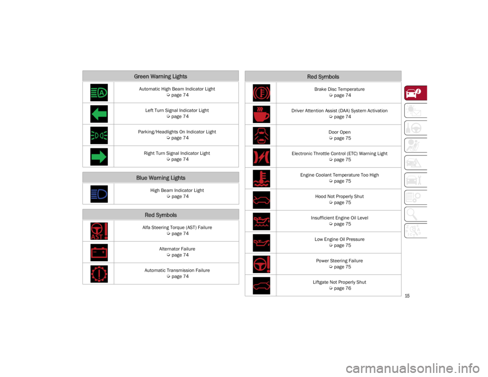
Green Warning Lights
Automatic High Beam Indicator Light
Ú
page 74
Left Turn Signal Indicator Light
Ú
page 74
Parking/Headlights On Indicator Light
Ú
page 74
Right Turn Signal Indicator Light
Ú
page 74
Blue Warning Lights
High Beam Indicator Light
Ú
page 74
Red Symbols
Alfa Steering Torque (AST) Failure
Ú
page 74
Alternator Failure
Ú
page 74
Automatic Transmission Failure
Ú
page 74
Brake Disc Temperature
Ú
page 74
Driver Attention Assist (DAA) System Activation
Ú
page 74
Door Open
Ú
page 75
Electronic Throttle Control (ETC) Warning Light
Ú
page 75
Engine Coolant Temperature Too High
Ú
page 75
Hood Not Properly Shut
Ú
page 75
Insufficient Engine Oil Level
Ú
page 75
Low Engine Oil Pressure
Ú
page 75
Power Steering Failure
Ú
page 75
Liftgate Not Properly Shut
Ú
page 76
Red Symbols
22_GU_OM_EN_USC_t.book Page 15
Page 24 of 256
GETTING TO KNOW YOUR VEHICLE
22
IGNITION SWITCH
KEYLESS PUSH BUTTON IGNITION
This feature allows the driver to operate the
ignition switch with the push of a button as long
as the key fob is in the passenger compartment.
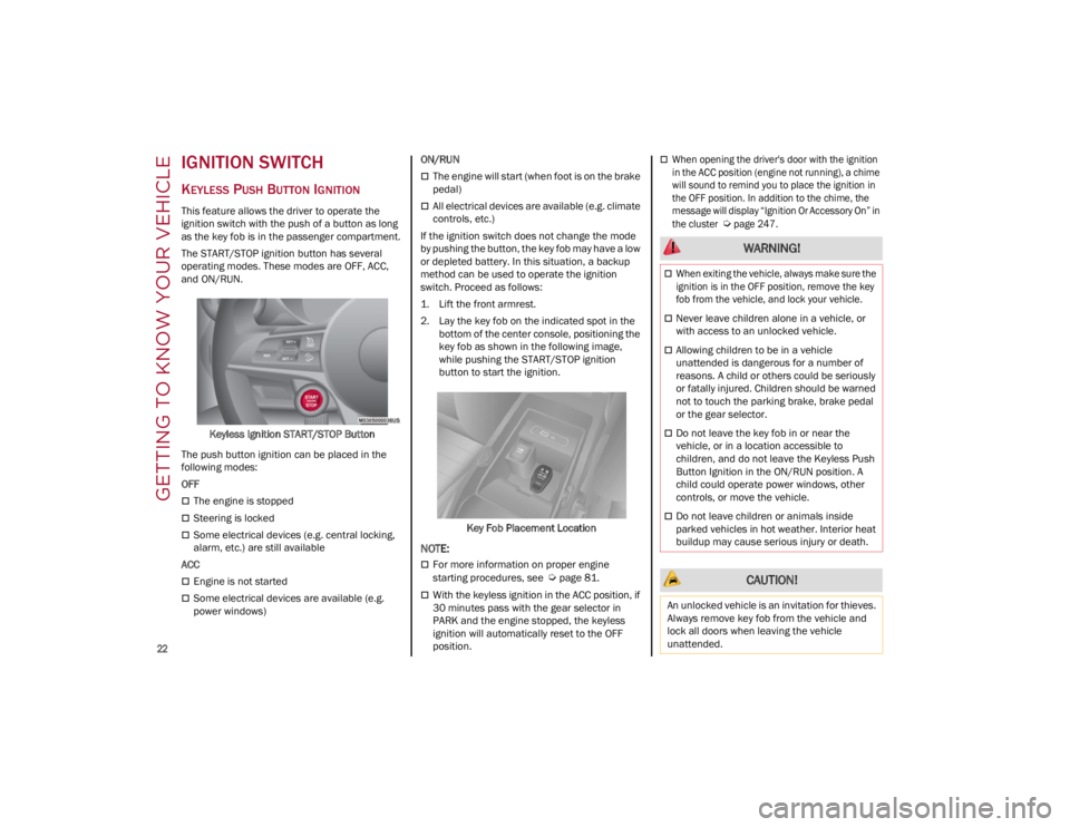
The START/STOP ignition button has several
operating modes. These modes are OFF, ACC,
and ON/RUN.Keyless Ignition START/STOP Button
The push button ignition can be placed in the
following modes:
OFF
The engine is stopped
Steering is locked
Some electrical devices (e.g. central locking,
alarm, etc.) are still available
ACC
Engine is not started
Some electrical devices are available (e.g.
power windows) ON/RUN
The engine will start (when foot is on the brake
pedal)
All electrical devices are available (e.g. climate
controls, etc.)
If the ignition switch does not change the mode
by pushing the button, the key fob may have a low
or depleted battery. In this situation, a backup
method can be used to operate the ignition
switch. Proceed as follows:
1. Lift the front armrest.
2. Lay the key fob on the indicated spot in the bottom of the center console, positioning the
key fob as shown in the following image,
while pushing the START/STOP ignition
button to start the ignition.
Key Fob Placement Location
NOTE:
For more information on proper engine
starting procedures, see
Ú
page 81.
With the keyless ignition in the ACC position, if
30 minutes pass with the gear selector in
PARK and the engine stopped, the keyless
ignition will automatically reset to the OFF
position.
When opening the driver's door with the ignition
in the ACC position (engine not running), a chime
will sound to remind you to place the ignition in
the OFF position. In addition to the chime, the
message will display “Ignition Or Accessory On” in
the cluster
Ú
page 247.
WARNING!
When exiting the vehicle, always make sure the
ignition is in the OFF position, remove the key
fob from the vehicle, and lock your vehicle.
Never leave children alone in a vehicle, or
with access to an unlocked vehicle.
Allowing children to be in a vehicle
unattended is dangerous for a number of
reasons. A child or others could be seriously
or fatally injured. Children should be warned
not to touch the parking brake, brake pedal
or the gear selector.
Do not leave the key fob in or near the
vehicle, or in a location accessible to
children, and do not leave the Keyless Push
Button Ignition in the ON/RUN position. A
child could operate power windows, other
controls, or move the vehicle.
Do not leave children or animals inside
parked vehicles in hot weather. Interior heat
buildup may cause serious injury or death.
CAUTION!
An unlocked vehicle is an invitation for thieves.
Always remove key fob from the vehicle and
lock all doors when leaving the vehicle
unattended.
22_GU_OM_EN_USC_t.book Page 22
Page 25 of 256
23
REMOTE START —
IF EQUIPPED
This system uses the key fob to start the
engine conveniently from outside the
vehicle while still maintaining security.
NOTE:
Obstructions between the vehicle and key fob
may reduce this range
Ú
page 247.
HOW TO USE REMOTE START
Push the Remote Start button on the key fob
twice within five seconds. The vehicle doors will
lock, the turn signals will flash twice, and the horn
will chirp twice. Pushing the Remote Start button
a third time shuts the engine off.
NOTE:
With Remote Start, the engine will only run for
15 minutes.
Remote Start can only be used twice.
If an engine fault is present or fuel level is low,
the vehicle will start and then shut down in 10
seconds.
The parking lights will turn on and remain on
during Remote Start mode.
For security, power window and power sunroof
(if equipped) operation is disabled when the
vehicle is in the Remote Start mode.
The ignition must be placed in the ACC position
before the Remote Start sequence can be
repeated for a third cycle.
All of the following conditions must be met before
the engine will remote start:
Gear selector in PARK
Doors closed
Hood closed
Liftgate closed
Hazard switch off
Brake switch inactive (brake pedal not
pressed)
Battery at an acceptable charge level
PANIC button not pushed
System not disabled from previous Remote
Start event
Vehicle Security system indicator flashing
Ignition in OFF position
Fuel level meets minimum requirement
Vehicle Security system is not signaling an
intrusion
Malfunction Indicator Light (MIL) is not
illuminated
TO EXIT REMOTE START MODE
To drive the vehicle after starting the Remote
Start system, either push and release the unlock
button on the key fob to unlock the doors, or
unlock the vehicle using Passive Entry via the
door handles, and disarm the Vehicle Security
system (if equipped). Then, prior to the end of the
15 minute cycle, push and release the START/
STOP ignition button while pressing the brake
pedal.
The Remote Start system will turn the engine off
if the Remote Start button is pushed again, or if
the engine is allowed to run for the entire
15 minute cycle.
REMOTE START COMFORT SYSTEMS —
I
F EQUIPPED
When Remote Start is activated, the heated
steering wheel and front heated seat features will
automatically activate when ambient
temperature is less than 39°F (4°C). These
features will stay on through the duration of
Remote Start.
NOTE:
This feature can be activated through the radio
system. Refer to the Information and Entertain -
ment System Owner’s Manual Supplement for
further information.
WARNING!
Do not start or run an engine in a closed
garage or confined area. Exhaust gas
contains Carbon Monoxide (CO) which is
odorless and colorless. Carbon Monoxide is
poisonous and can cause serious injury or
death when inhaled.
Keep key fobs away from children. Operation
of the Remote Start system, windows, door
locks or other controls could cause serious
injury or death.
22_GU_OM_EN_USC_t.book Page 23
Page 31 of 256
29
NOTE:
Always use this device when carrying children.
After engaging the child lock on both rear doors,
check for effective engagement by trying to open
a door with the internal handle. Once the
Child-Protection Door Lock system is engaged, it
is impossible to open the doors from inside the
vehicle. Before getting out of the vehicle, be sure
to check that there is no one left inside.
STEERING WHEEL
MANUAL TILT/TELESCOPING STEERING
C
OLUMN
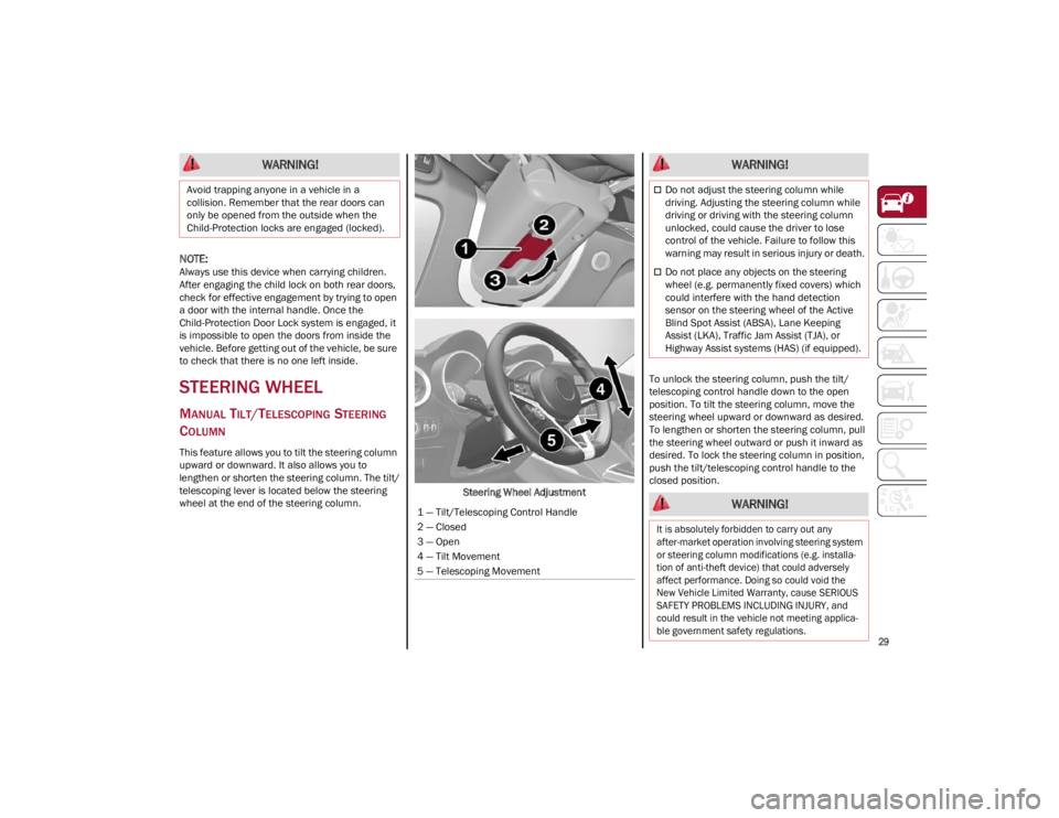
This feature allows you to tilt the steering column
upward or downward. It also allows you to
lengthen or shorten the steering column. The tilt/
telescoping lever is located below the steering
wheel at the end of the steering column. Steering Wheel AdjustmentTo unlock the steering column, push the tilt/
telescoping control handle down to the open
position. To tilt the steering column, move the
steering wheel upward or downward as desired.
To lengthen or shorten the steering column, pull
the steering wheel outward or push it inward as
desired. To lock the steering column in position,
push the tilt/telescoping control handle to the
closed position.
WARNING!
Avoid trapping anyone in a vehicle in a
collision. Remember that the rear doors can
only be opened from the outside when the
Child-Protection locks are engaged (locked).
1 — Tilt/Telescoping Control Handle
2 — Closed
3 — Open
4 — Tilt Movement
5 — Telescoping Movement
WARNING!
Do not adjust the steering column while
driving. Adjusting the steering column while
driving or driving with the steering column
unlocked, could cause the driver to lose
control of the vehicle. Failure to follow this
warning may result in serious injury or death.
Do not place any objects on the steering
wheel (e.g. permanently fixed covers) which
could interfere with the hand detection
sensor on the steering wheel of the Active
Blind Spot Assist (ABSA), Lane Keeping
Assist (LKA), Traffic Jam Assist (TJA), or
Highway Assist systems (HAS) (if equipped).
WARNING!
It is absolutely forbidden to carry out any
after-market operation involving steering system
or steering column modifications (e.g. installa -
tion of anti-theft device) that could adversely
affect performance. Doing so could void the
New Vehicle Limited Warranty, cause SERIOUS
SAFETY PROBLEMS INCLUDING INJURY, and
could result in the vehicle not meeting applica -
ble government safety regulations.
22_GU_OM_EN_USC_t.book Page 29
Page 32 of 256
GETTING TO KNOW YOUR VEHICLE
30
HEATED STEERING WHEEL —
I
F EQUIPPED
The steering wheel contains a heating
element that helps warm your hands in
cold weather. The heated steering
wheel has only one temperature setting.
The heated steering wheel may not turn on when
it is already warm.
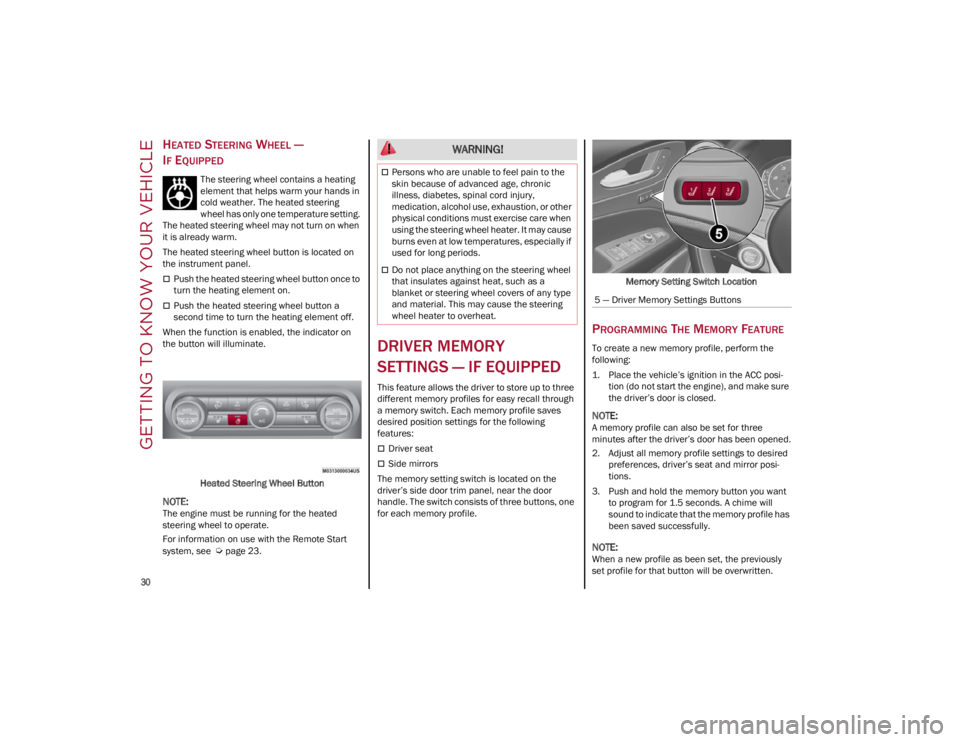
The heated steering wheel button is located on
the instrument panel.
Push the heated steering wheel button once to
turn the heating element on.
Push the heated steering wheel button a
second time to turn the heating element off.
When the function is enabled, the indicator on
the button will illuminate.
Heated Steering Wheel Button
NOTE:
The engine must be running for the heated
steering wheel to operate.
For information on use with the Remote Start
system, see
Ú
page 23.
DRIVER MEMORY
SETTINGS — IF EQUIPPED
This feature allows the driver to store up to three
different memory profiles for easy recall through
a memory switch. Each memory profile saves
desired position settings for the following
features:
Driver seat
Side mirrors
The memory setting switch is located on the
driver’s side door trim panel, near the door
handle. The switch consists of three buttons, one
for each memory profile. Memory Setting Switch Location
PROGRAMMING THE MEMORY FEATURE
To create a new memory profile, perform the
following:
1. Place the vehicle’s ignition in the ACC posi
-
tion (do not start the engine), and make sure
the driver’s door is closed.
NOTE:
A memory profile can also be set for three
minutes after the driver’s door has been opened.
2. Adjust all memory profile settings to desired preferences, driver’s seat and mirror posi -
tions.
3. Push and hold the memory button you want to program for 1.5 seconds. A chime will
sound to indicate that the memory profile has
been saved successfully.
NOTE:
When a new profile as been set, the previously
set profile for that button will be overwritten.
WARNING!
Persons who are unable to feel pain to the
skin because of advanced age, chronic
illness, diabetes, spinal cord injury,
medication, alcohol use, exhaustion, or other
physical conditions must exercise care when
using the steering wheel heater. It may cause
burns even at low temperatures, especially if
used for long periods.
Do not place anything on the steering wheel
that insulates against heat, such as a
blanket or steering wheel covers of any type
and material. This may cause the steering
wheel heater to overheat.
5 — Driver Memory Settings Buttons
22_GU_OM_EN_USC_t.book Page 30
Page 44 of 256
GETTING TO KNOW YOUR VEHICLE
42
If you have any problems, or require assistance,
please call toll-free 1-800-355-3515 or, on the
Internet at
HomeLink.com
for information or
assistance.
EXTERIOR LIGHTS
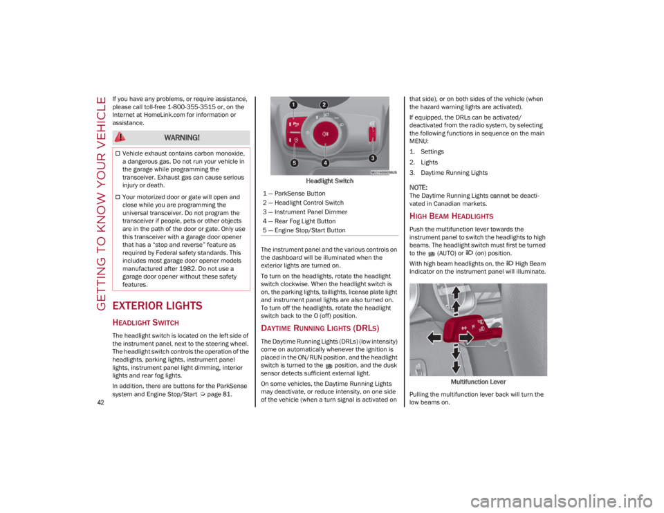
HEADLIGHT SWITCH
The headlight switch is located on the left side of
the instrument panel, next to the steering wheel.
The headlight switch controls the operation of the
headlights, parking lights, instrument panel
lights, instrument panel light dimming, interior
lights and rear fog lights.
In addition, there are buttons for the ParkSense
system and Engine Stop/Start
Ú
page 81. Headlight Switch
The instrument panel and the various controls on
the dashboard will be illuminated when the
exterior lights are turned on.
To turn on the headlights, rotate the headlight
switch clockwise. When the headlight switch is
on, the parking lights, taillights, license plate light
and instrument panel lights are also turned on.
To turn off the headlights, rotate the headlight
switch back to the O (off) position.
DAYTIME RUNNING LIGHTS (DRLS)
The Daytime Running Lights (DRLs) (low intensity)
come on automatically whenever the ignition is
placed in the ON/RUN position, and the headlight
switch is turned to the position, and the dusk
sensor detects sufficient external light.
On some vehicles, the Daytime Running Lights
may deactivate, or reduce intensity, on one side
of the vehicle (when a turn signal is activated on that side), or on both sides of the vehicle (when
the hazard warning lights are activated).
If equipped, the DRLs can be activated/
deactivated from the radio system, by selecting
the following functions in sequence on the main
MENU:
1. Settings
2. Lights
3. Daytime Running Lights
NOTE:
The Daytime Running Lights
cannot be deacti -
vated in Canadian markets.
HIGH BEAM HEADLIGHTS
Push the multifunction lever towards the
instrument panel to switch the headlights to high
beams. The headlight switch must first be turned
to the (AUTO) or (on) position.
With high beam headlights on, the High Beam
Indicator on the instrument panel will illuminate.
Multifunction Lever
Pulling the multifunction lever back will turn the
low beams on.
WARNING!
Vehicle exhaust contains carbon monoxide,
a dangerous gas. Do not run your vehicle in
the garage while programming the
transceiver. Exhaust gas can cause serious
injury or death.
Your motorized door or gate will open and
close while you are programming the
universal transceiver. Do not program the
transceiver if people, pets or other objects
are in the path of the door or gate. Only use
this transceiver with a garage door opener
that has a “stop and reverse” feature as
required by Federal safety standards. This
includes most garage door opener models
manufactured after 1982. Do not use a
garage door opener without these safety
features.1 — ParkSense Button
2 — Headlight Control Switch
3 — Instrument Panel Dimmer
4 — Rear Fog Light Button
5 — Engine Stop/Start Button
22_GU_OM_EN_USC_t.book Page 42
Page 45 of 256
43
AUTOMATIC HEADLIGHTS
This system automatically turns the headlights on
or off according to ambient light levels. To turn
the system on, rotate the headlight switch to the (AUTO) position.
NOTE:
The function can only operate with the ignition in
the ON/RUN position.
To turn the automatic headlights off, turn the
headlight switch out of the (AUTO) position.
FLASH-TO-PASS
You can signal another vehicle with your
headlights by lightly pulling the multifunction
lever toward you. This will cause the high beam
headlights to turn on, and remain on, until the
lever is released.
AUTOMATIC HIGH BEAM HEADLIGHTS —
I
F EQUIPPED
The Automatic High Beam Headlights system
provides increased forward lighting at night by
automating high beam control through the use of
a camera mounted on the windshield. This
camera detects vehicle specific light and
automatically switches from high beams to low
beams until the approaching vehicle is out of
view.
This function is enabled with the radio system,
and can only be activated with the light switch
turned to (auto).
If the high beam headlights are on, the blue icon/
warning light will illuminate in the instrument
panel. When the speed is higher than 25 mph (40 km/h)
and the function is active, the lights will turn off if
the multifunction lever is pushed again.
When the speed is lower than 15 mph (25 km/h)
and the function is active, the function switches
the high beam headlights off.
If the high beam headlights are operated quickly
again (pushing the multifunction lever towards
the instrument panel), the warning light/icon
will illuminate in the instrument panel, and the
high beam headlights will turn on constantly until
the speed exceeds 25 mph (40 km/h).
When the speed of 25 mph (40 km/h) is
exceeded again, the automatic functioning is
reactivated.
If the multifunction lever is pushed again with the
Automatic High Beam Headlights activated, the
Automatic High Beam Headlights function
deactivates.
To deactivate the automatic headlight function,
rotate the headlight switch to the position.
NOTE:
If the system recognizes heavy traffic areas,
the automatic functions remain disabled
independently of the vehicle’s speed.
The Automatic High Beam functionality may
also be influenced by:
• Reflections on road signs
• Dim headlights from oncoming traffic
• Poor weather conditions
• Presence of dirt or other obstructions on
the sensor
• Damage to the windshield
PARKING LIGHTS
To turn on the parking lights and instrument
panel lights, rotate the headlight switch clockwise
to the position. All of the parking lights will turn
on for eight minutes, and opening the door
activates an audible warning.
To leave only the lights on one side (right/left)
illuminated, move the multifunction lever
(located on the left side of the steering wheel) to
the side that you want to remain on. With the
parking lights on, the indicator light on the
instrument panel will illuminate.
To turn off the parking lights, rotate the headlight
switch back to the O (off) position.
HEADLIGHT OFF DELAY
To assist when exiting the vehicle, the “Headlight
Off Delay” feature will leave the headlights on for
up to 90 seconds. This delay is initiated when the
ignition is placed in the OFF position while the
headlight switch is on, and then the headlight
switch is cycled off. Headlight delay can be
canceled by either turning on the headlights or
side lights, or by placing the ignition in the ON
position.
The function can be activated from the radio
system by selecting the following functions in
sequence on the main menu:
1. Settings
2. Lights
3. Headlight Off Delay
22_GU_OM_EN_USC_t.book Page 43