ALFA ROMEO STELVIO 2023 Owners Manual
Manufacturer: ALFA ROMEO, Model Year: 2023, Model line: STELVIO, Model: ALFA ROMEO STELVIO 2023Pages: 268, PDF Size: 10.36 MB
Page 221 of 268
219
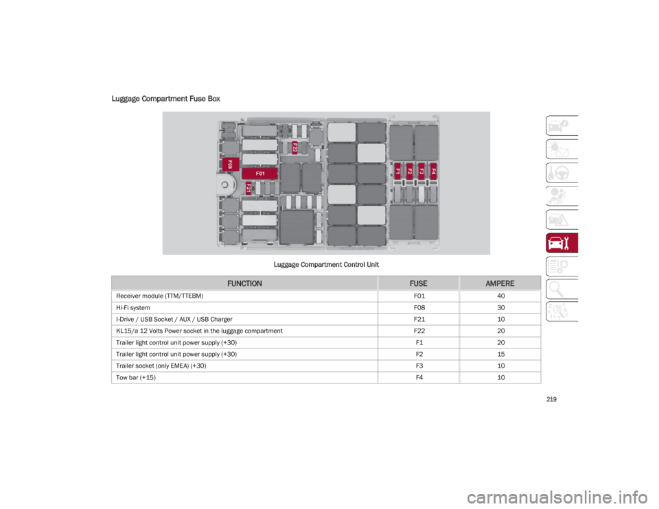
Luggage Compartment Fuse Box
Luggage Compartment Control Unit
FUNCTIONFUSEAMPERE
Receiver module (TTM/TTEBM)F0140
Hi-Fi system F0830
I-Drive / USB Socket / AUX / USB Charger F2110
KL15/a 12 Volts Power socket in the luggage compartment F2220
Trailer light control unit power supply (+30) F120
Trailer light control unit power supply (+30) F215
Trailer socket (only EMEA) (+30) F310
Tow bar (+15) F410
23_GU_OM_EN_USC_t.book Page 219
Page 222 of 268
SERVICING AND MAINTENANCE
220
BULB REPLACEMENT
General Instructions
Before replacing a bulb, check the contacts for oxidation.
Replace blown bulbs with others of the same type and power.
After replacing a headlight bulb, always check its alignment.
When a light is not working, check that the corresponding fuse is intact before changing the bulb.
NOTE:
In some particular climate conditions, such as low temperature, humidity, or after washing the vehicle, a thin condensation layer may form on the
internal surfaces of the front and rear headlights. This condensation will disappear after switching on the headlights.
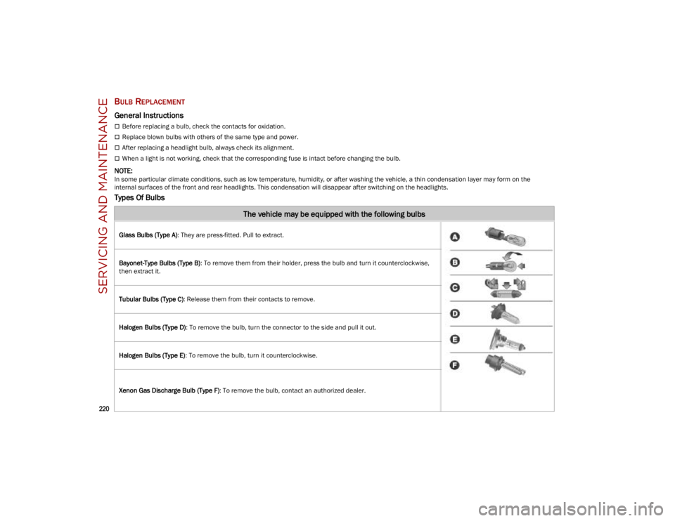
Types Of Bulbs
The vehicle may be equipped with the following bulbs
Glass Bulbs (Type A): They are press-fitted. Pull to extract.
Bayonet-Type Bulbs (Type B) : To remove them from their holder, press the bulb and turn it counterclockwise,
then extract it.
Tubular Bulbs (Type C) : Release them from their contacts to remove.
Halogen Bulbs (Type D) : To remove the bulb, turn the connector to the side and pull it out.
Halogen Bulbs (Type E) : To remove the bulb, turn it counterclockwise.
Xenon Gas Discharge Bulb (Type F) : To remove the bulb, contact an authorized dealer.
23_GU_OM_EN_USC_t.book Page 220
Page 223 of 268
221
Replacement Bulbs
*Only for basic version headlight with halogen main beam/dipped beam headlights
Replacing Exterior Bulbs
NOTE:
Only replace bulbs when the engine is off.
Also ensure that the engine is cold, to prevent the
risk of burns.
Front Light Cluster
Direction Indicators
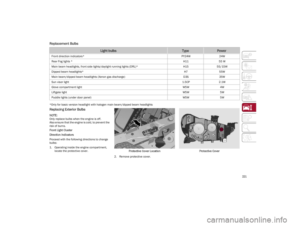
Proceed with the following directions to change
bulbs:
1. Operating inside the engine compartment, locate the protective cover. Protective Cover Location
2. Remove protective cover. Protective Cover
Light bulbsTypePower
Front direction indicators*
PY24W24W
Rear Fog lights * H1155 W
Main beam headlights, front side lights/daylight running lights (DRL)* H1555/15W
Dipped beam headlights* H755W
Main beam/dipped beam headlights (Xenon gas discharge) D3S35W
Sun visor light 1.5CP2.1W
Glove compartment light W5W4W
Liftgate light W5W5W
Puddle lights (under door panel) W5W5W
23_GU_OM_EN_USC_t.book Page 221
Page 224 of 268
SERVICING AND MAINTENANCE
222
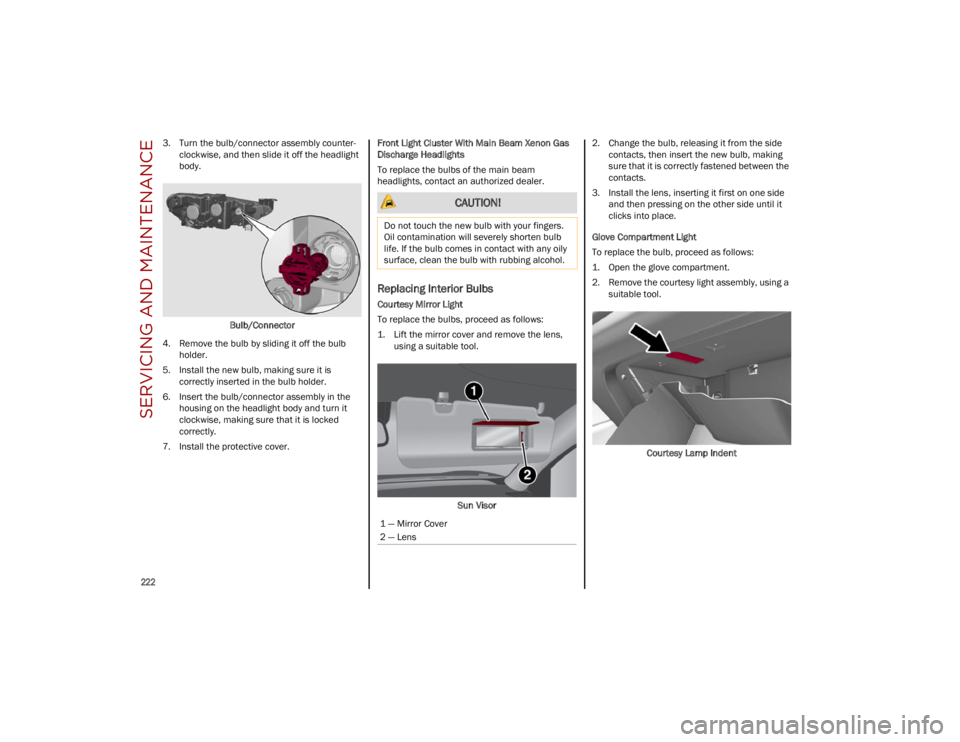
3. Turn the bulb/connector assembly counter-
clockwise, and then slide it off the headlight
body.
Bulb/Connector
4. Remove the bulb by sliding it off the bulb holder.
5. Install the new bulb, making sure it is correctly inserted in the bulb holder.
6. Insert the bulb/connector assembly in the housing on the headlight body and turn it
clockwise, making sure that it is locked
correctly.
7. Install the protective cover. Front Light Cluster With Main Beam Xenon Gas
Discharge Headlights
To replace the bulbs of the main beam
headlights, contact an authorized dealer.
Replacing Interior Bulbs
Courtesy Mirror Light
To replace the bulbs, proceed as follows:
1. Lift the mirror cover and remove the lens,
using a suitable tool.
Sun Visor 2. Change the bulb, releasing it from the side
contacts, then insert the new bulb, making
sure that it is correctly fastened between the
contacts.
3. Install the lens, inserting it first on one side and then pressing on the other side until it
clicks into place.
Glove Compartment Light
To replace the bulb, proceed as follows:
1. Open the glove compartment.
2. Remove the courtesy light assembly, using a suitable tool.
Courtesy Lamp Indent
CAUTION!
Do not touch the new bulb with your fingers.
Oil contamination will severely shorten bulb
life. If the bulb comes in contact with any oily
surface, clean the bulb with rubbing alcohol.
1 — Mirror Cover
2 — Lens
23_GU_OM_EN_USC_t.book Page 222
Page 225 of 268
223
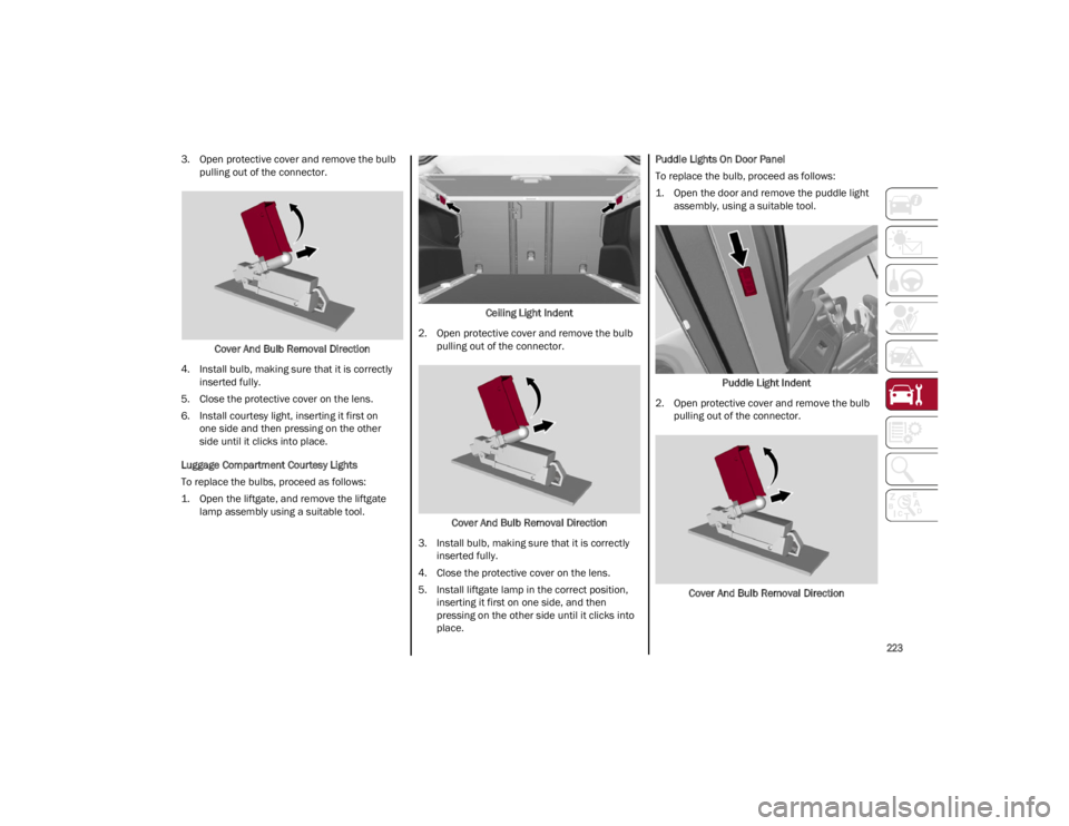
3. Open protective cover and remove the bulb pulling out of the connector.
Cover And Bulb Removal Direction
4. Install bulb, making sure that it is correctly inserted fully.
5. Close the protective cover on the lens.
6. Install courtesy light, inserting it first on one side and then pressing on the other
side until it clicks into place.
Luggage Compartment Courtesy Lights
To replace the bulbs, proceed as follows:
1. Open the liftgate, and remove the liftgate lamp assembly using a suitable tool. Ceiling Light Indent
2. Open protective cover and remove the bulb pulling out of the connector.
Cover And Bulb Removal Direction
3. Install bulb, making sure that it is correctly inserted fully.
4. Close the protective cover on the lens.
5. Install liftgate lamp in the correct position, inserting it first on one side, and then
pressing on the other side until it clicks into
place. Puddle Lights On Door Panel
To replace the bulb, proceed as follows:
1. Open the door and remove the puddle light
assembly, using a suitable tool.
Puddle Light Indent
2. Open protective cover and remove the bulb pulling out of the connector.
Cover And Bulb Removal Direction
23_GU_OM_EN_USC_t.book Page 223
Page 226 of 268
SERVICING AND MAINTENANCE
224
3. Install bulb, making sure that it is correctlyinserted fully.
4. Close the protective cover on the lens.
5. Install puddle light in the correct position, inserting it first on one side and then pressing
on the other side until it clicks into place.
TIRES
TIRE SAFETY INFORMATION
Tire safety information will cover aspects of
the following information: Tire Markings,
Tire Identification Numbers, Tire Terminology and
Definitions, Tire Pressures, and Tire Loading.
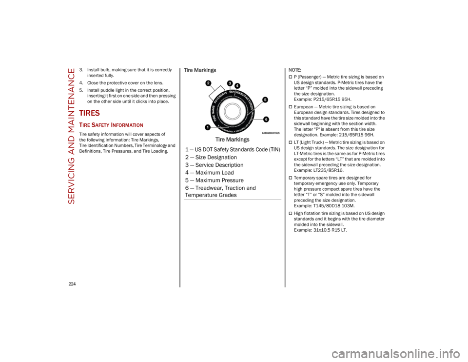
Tire Markings
Tire Markings
NOTE:
P (Passenger) — Metric tire sizing is based on
US design standards. P-Metric tires have the
letter “P” molded into the sidewall preceding
the size designation.
Example: P215/65R15 95H.
European — Metric tire sizing is based on
European design standards. Tires designed to
this standard have the tire size molded into the
sidewall beginning with the section width.
The letter "P" is absent from this tire size
designation. Example: 215/65R15 96H.
LT (Light Truck) — Metric tire sizing is based on
US design standards. The size designation for
LT-Metric tires is the same as for P-Metric tires
except for the letters “LT” that are molded into
the sidewall preceding the size designation.
Example: LT235/85R16.
Temporary spare tires are designed for
temporary emergency use only. Temporary
high pressure compact spare tires have the
letter “T” or “S” molded into the sidewall
preceding the size designation.
Example: T145/80D18 103M.
High flotation tire sizing is based on US design
standards and it begins with the tire diameter
molded into the sidewall.
Example: 31x10.5 R15 LT.
1 — US DOT Safety Standards Code (TIN)
2 — Size Designation
3 — Service Description
4 — Maximum Load
5 — Maximum Pressure
6 — Treadwear, Traction and
Temperature Grades
23_GU_OM_EN_USC_t.book Page 224
Page 227 of 268
225
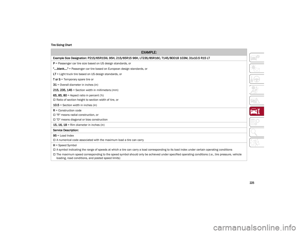
Tire Sizing Chart
EXAMPLE:
Example Size Designation: P215/65R15XL 95H, 215/65R15 96H, LT235/85R16C, T145/80D18 103M, 31x10.5 R15 LT
P
= Passenger car tire size based on US design standards, or
"....blank...." = Passenger car tire based on European design standards, or
LT = Light truck tire based on US design standards, or
T or S = Temporary spare tire or
31 = Overall diameter in inches (in)
215, 235, 145 = Section width in millimeters (mm)
65, 85, 80 = Aspect ratio in percent (%)
Ratio of section height to section width of tire, or
10.5 = Section width in inches (in)
R = Construction code
"R" means radial construction, or
"D" means diagonal or bias construction
15, 16, 18 = Rim diameter in inches (in)
Service Description:
95 = Load Index
A numerical code associated with the maximum load a tire can carry
H = Speed Symbol
A symbol indicating the range of speeds at which a tire can carry a load corresponding to its load index under certain operating conditions
The maximum speed corresponding to the speed symbol should only be achieved under specified operating conditions (i.e., tire pressure, vehicle
loading, road conditions, and posted speed limits)
23_GU_OM_EN_USC_t.book Page 225
Page 228 of 268
SERVICING AND MAINTENANCE
226
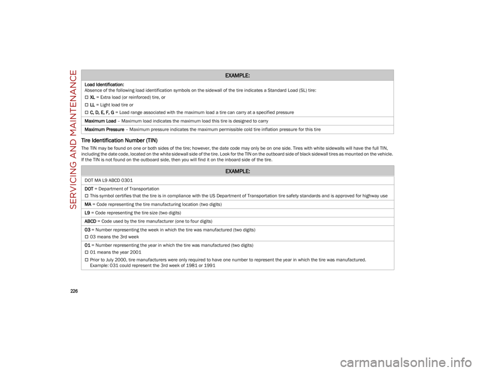
Tire Identification Number (TIN)
The TIN may be found on one or both sides of the tire; however, the date code may only be on one side. Tires with white sidewalls will have the full TIN,
including the date code, located on the white sidewall side of the tire. Look for the TIN on the outboard side of black sidewall tires as mounted on the vehicle.
If the TIN is not found on the outboard side, then you will find it on the inboard side of the tire.Load Identification:
Absence of the following load identification symbols on the sidewall of the tire indicates a Standard Load (SL) tire:
XL
= Extra load (or reinforced) tire, or
LL = Light load tire or
C, D, E, F, G = Load range associated with the maximum load a tire can carry at a specified pressure
Maximum Load – Maximum load indicates the maximum load this tire is designed to carry
Maximum Pressure – Maximum pressure indicates the maximum permissible cold tire inflation pressure for this tire
EXAMPLE:
EXAMPLE:
DOT MA L9 ABCD 0301
DOT = Department of Transportation
This symbol certifies that the tire is in compliance with the US Department of Transportation tire safety standards and is approved for highway use
MA = Code representing the tire manufacturing location (two digits)
L9 = Code representing the tire size (two digits)
ABCD = Code used by the tire manufacturer (one to four digits)
03 = Number representing the week in which the tire was manufactured (two digits)
03 means the 3rd week
01 = Number representing the year in which the tire was manufactured (two digits)
01 means the year 2001
Prior to July 2000, tire manufacturers were only required to have one number to represent the year in which the tire was manufactured.
Example: 031 could represent the 3rd week of 1981 or 1991
23_GU_OM_EN_USC_t.book Page 226
Page 229 of 268
227
Tire Terminology And Definitions
Tire Loading And Tire Pressure
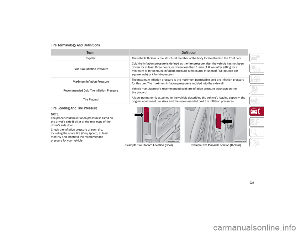
NOTE:
The proper cold tire inflation pressure is listed on
the driver’s side B-pillar or the rear edge of the
driver's side door.
Check the inflation pressure of each tire,
including the spare tire (if equipped), at least
monthly and inflate to the recommended
pressure for your vehicle.Example Tire Placard Location (Door)Example Tire Placard Location (B-pillar)
TermDefinition
B-pillarThe vehicle B-pillar is the structural member of the body located behind the front door.
Cold Tire Inflation Pressure Cold tire inflation pressure is defined as the tire pressure after the vehicle has not been
driven for at least three hours, or driven less than 1 mile (1.6 km) after sitting for a
minimum of three hours. Inflation pressure is measured in units of PSI (pounds per
square inch) or kPa (kilopascals).
Maximum Inflation Pressure The maximum inflation pressure is the maximum permissible cold tire inflation pressure
for this tire. The maximum inflation pressure is molded into the sidewall.
Recommended Cold Tire Inflation Pressure Vehicle manufacturer's recommended cold tire inflation pressure as shown on the
tire placard.
Tire Placard A label permanently attached to the vehicle describing the vehicle’s loading capacity, the
original equipment tire sizes and the recommended cold tire inflation pressures.
23_GU_OM_EN_USC_t.book Page 227
Page 230 of 268
SERVICING AND MAINTENANCE
228
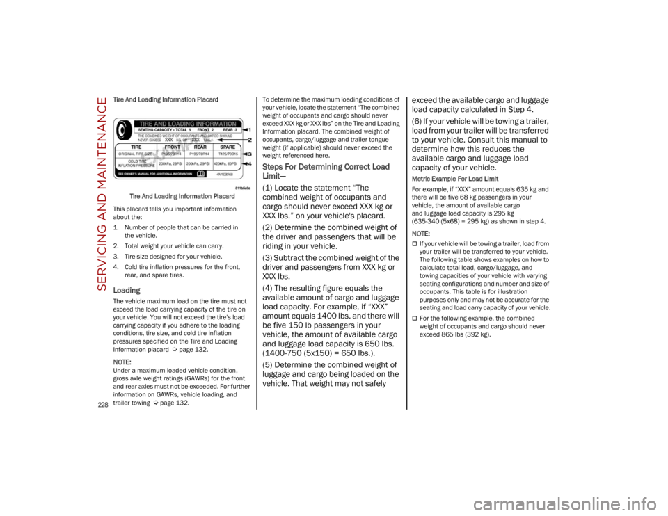
Tire And Loading Information PlacardTire And Loading Information Placard
This placard tells you important information
about the:
1. Number of people that can be carried in the vehicle.
2. Total weight your vehicle can carry.
3. Tire size designed for your vehicle.
4. Cold tire inflation pressures for the front, rear, and spare tires.
Loading
The vehicle maximum load on the tire must not
exceed the load carrying capacity of the tire on
your vehicle. You will not exceed the tire's load
carrying capacity if you adhere to the loading
conditions, tire size, and cold tire inflation
pressures specified on the Tire and Loading
Information placard
Ú
page 132.
NOTE:
Under a maximum loaded vehicle condition,
gross axle weight ratings (GAWRs) for the front
and rear axles must not be exceeded. For further
information on GAWRs, vehicle loading, and
trailer towing
Ú
page 132. To determine the maximum loading conditions of
your vehicle, locate the statement “The combined
weight of occupants and cargo should never
exceed XXX kg or XXX lbs” on the Tire and Loading
Information placard. The combined weight of
occupants, cargo/luggage and trailer tongue
weight (if applicable) should never exceed the
weight referenced here.
Steps For Determining Correct Load
Limit—
(1) Locate the statement “The
combined weight of occupants and
cargo should never exceed XXX kg or
XXX lbs.” on your vehicle's placard.
(2) Determine the combined weight of
the driver and passengers that will be
riding in your vehicle.
(3) Subtract the combined weight of the
driver and passengers from XXX kg or
XXX lbs.
(4) The resulting figure equals the
available amount of cargo and luggage
load capacity. For example, if “XXX”
amount equals 1400 lbs. and there will
be five 150 lb passengers in your
vehicle, the amount of available cargo
and luggage load capacity is 650 lbs.
(1400-750 (5x150) = 650 lbs.).
(5) Determine the combined weight of
luggage and cargo being loaded on the
vehicle. That weight may not safely
exceed the available cargo and luggage
load capacity calculated in Step 4.
(6) If your vehicle will be towing a trailer,
load from your trailer will be transferred
to your vehicle. Consult this manual to
determine how this reduces the
available cargo and luggage load
capacity of your vehicle.
Metric Example For Load Limit
For example, if “XXX” amount equals 635 kg and
there will be five 68 kg passengers in your
vehicle, the amount of available cargo
and luggage load capacity is 295 kg
(635-340 (5x68) = 295 kg) as shown in step 4.
NOTE:
If your vehicle will be towing a trailer, load from
your trailer will be transferred to your vehicle.
The following table shows examples on how to
calculate total load, cargo/luggage, and
towing capacities of your vehicle with varying
seating configurations and number and size of
occupants. This table is for illustration
purposes only and may not be accurate for the
seating and load carry capacity of your vehicle.
For the following example, the combined
weight of occupants and cargo should never
exceed 865 lbs (392 kg).
23_GU_OM_EN_USC_t.book Page 228