window ASTON MARTIN DB AR1 Q 2003 Owners Guide
[x] Cancel search | Manufacturer: ASTON MARTIN, Model Year: 2003, Model line: DB AR1 Q, Model: ASTON MARTIN DB AR1 Q 2003Pages: 279, PDF Size: 3.77 MB
Page 103 of 279

E - Security Systems
1-E-4
Unlocking the Car, Disarming the Alarm
Point the key fob towards the rear window and press the left button once.
The following events will occur:
1. The green light on the key fob will light while the left button is pressed.
2. The car doors and fuel filler flap will unlock.
3. The direction indicators will flash (in markets where visible alarm signals
are permitted and programmed).
4. The alarm system will be switched off.
Locking the Car, Arming the Alarm
Point the key fob towards the rear window and press the left button. The
following events will occur:
1. The green light on the key fob will light while the left button is pressed.
2. The car doors and fuel filler flap will lock.
3. The direction indicators will flash once (in markets where visible alarm
signals are permitted).
4. The alarm system will be switched on.
Alarm and Security System Protection
With the alarm system armed, any attempt to open a door, the boot or the
bonnet will result in full alarm activation.
(See also the engine immobilisation protection afforded by the PATs system)
Page 141 of 279

F - Owner Maintenance
1-F-32
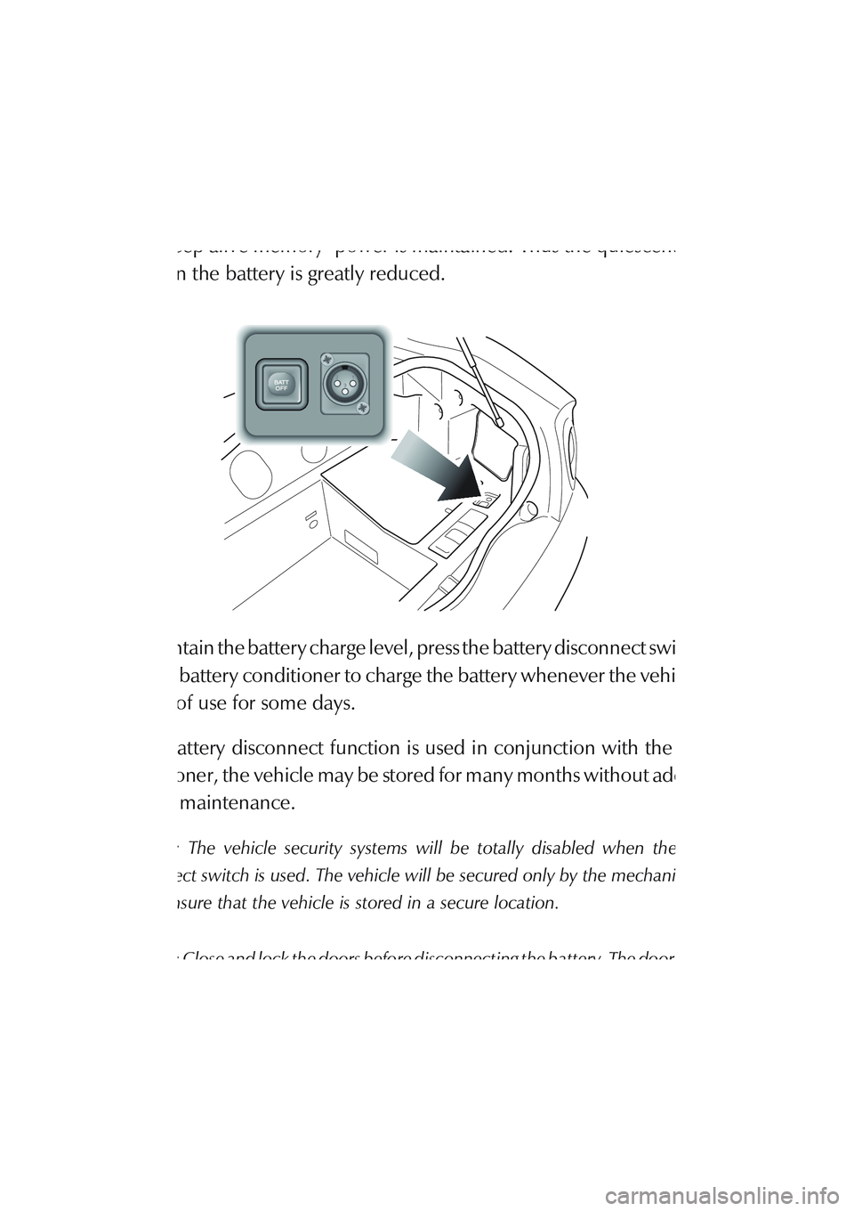
The Battery Disconnect Switch
The battery disconnect switch is located in the R/H side wall trim panel of
the boot. When actuated, power to all control modules is disconnected and
only ‘keep alive memory’ power is maintained. Thus the quiescent power
drain on the battery is greatly reduced.
To maintain the battery charge level, press the battery disconnect switch and
use the battery conditioner to charge the battery whenever the vehicle is to
be out of use for some days.
If the battery disconnect function is used in conjunction with the battery
conditioner, the vehicle may be stored for many months without additional
battery maintenance.
Caution: The vehicle security systems will be totally disabled when the battery
disconnect switch is used. The vehicle will be secured only by the mechanical door
locks. Ensure that the vehicle is stored in a secure location.
Caution: Close and lock the doors before disconnecting the battery. The door window
seals will be damaged if the door is closed or opened when the battery is disconnected.
Page 144 of 279

F - Owner Maintenance
1-F-35
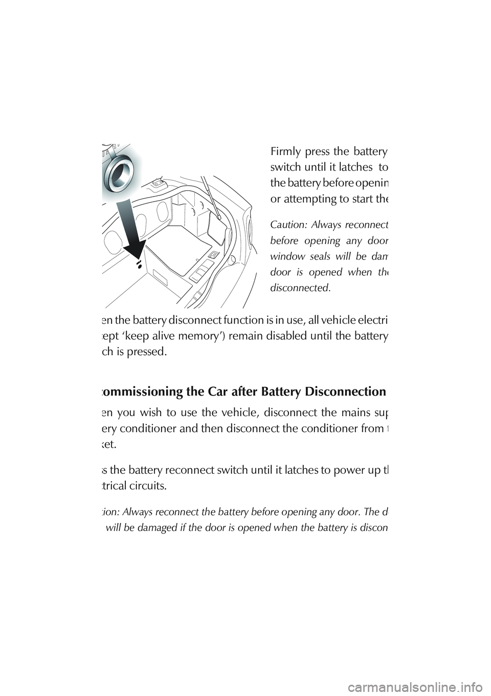
The Battery Reconnect Switch
The battery reconnect switch is
located in front wall of the boot.
Firmly press the battery reconnect
switch until it latches to reconnect
the battery before opening the doors
or attempting to start the vehicle.
Caution: Always reconnect the battery
before opening any door. The door
window seals will be damaged if the
door is opened when the battery is
disconnected.
When the battery disconnect function is in use, all vehicle electrical systems
(except ‘keep alive memory’) remain disabled until the battery reconnect
switch is pressed.
Recommissioning the Car after Battery Disconnection
When you wish to use the vehicle, disconnect the mains supply to the
battery conditioner and then disconnect the conditioner from the vehicle
socket.
Press the battery reconnect switch until it latches to power up the vehicles
electrical circuits.
Caution: Always reconnect the battery before opening any door. The door window
seals will be damaged if the door is opened when the battery is disconnected.
Start and run the vehicle as described in the 'Driving' section.
Page 148 of 279

F - Owner Maintenance
1-F-39
Fuse Lists
Passenger Footwell Fusebox - Right Hand
F1 5A Passive Anti-Theft Module
F2 20A Cigar Lighter
F3 10A Diagnostic Sockets, Radio, Air Conditioning, Driver's
Door Mirror and Window
F4 5A Seat Switches and Heaters
F5 10A Indicator Flasher
F6 10A Ignition Coils 1-6
F7 10A Interior Lamp Cluster
F8 10A Ignition Coils 7-12
F9 20A RHS Seat Heater Relay, RHS Seat Module
F10 10A Dimmer, Passive Anti-Theft Module, Radio
F11 10A Door Mirrors
F12 5A Diagnostic Sockets
F13 25A Not used
F14 10A Hazard Flasher Unit
F15 20A Wiper Logic Module and Wiper Stalk
F16 30A ABS Control Unit
F17 20A Wiper Motor, Logic Module and Wiper Stalk
F18 30A ABS Control Unit
F19 10A Air Conditioning LH Blower Motor
F20 5A Gearshift Interlock Module, Traction Control Switch,
Interior, Map & Courtesy Lamps
F21 10A Air Conditioning RH Blower Motor
F22 10A Powertrain and Transmission control Modules - Keep
Alive Memory
Page 149 of 279

F - Owner Maintenance
1-F-40
Passenger Footwell Fusebox - Left Hand
F1 15A Accessory Terminal
F2 10A Transmission Control Module, Gearshift Interlock
Module, PRND Switch
F3 5A Headlamp Relay, Instrument Pack, Dimmer Unit
F4 10A Multi Function Unit, Air-Conditioning In-Car Sensor,
Anti-Lock Brakes Control Unit
F5 5A Traction Control Switch, Alternator Regulator, Heated
Front Screen Control
F6 10A Rear Fog Switch, RH Dip Beam
F7 30A Starter Relay
F8 10A LH Dip Beam
F9 20A LHS Seat Heater Relay, LHS Seat Module
F10 40A Heated Front Screen Controller
F11 10A RH Horn
F12 30A LH Rad Cooling Fan
F13 10A LH Horn
F14 30A RH Rad Cooling Fan
F15 30A Primary Powertrain Control Module RHS
F16 10A Multi-Function Unit, Central Locking Module, Air
Conditioning Control Panel, Alarm Sounder
F17 30A Secondary Powertrain Control Module LHS
F18 5A Interior Map Lights, Instrument Pack,
RH Rad Module
F19 10A RH Main Beam
F20 20A Window Lift Cut Out, Accessory Terminal,
Air Conditioning Clutch Relay
F21 10A Instrument Pack, LH Main Beam
F22 25A Front Fog Relay
Page 161 of 279

F - Owner Maintenance
1-F-52
Door Edge Lights
1. Taking care to protect the paint
work, use a screwdriver to lever the
light assembly from its location in
the lower door edge.
2. Remove the bulb from the light
assembly and fit a replacement bulb.
3. Refit the assembly to the door,
pushing firmly until it clips into place.
Central High Mounted Stop Lamp
The high mounted stop lamp is fitted in the boot lid. It is recommended that
your have your dealer change the high mounted stop lamp if necessary.
Electric Window Reset Procedure
If either the battery or the window controllers are disconnected, the window
controller will lose its memory of the window maximum up and down
positions. The window controller memory may be checked and reset as
follows:
Page 162 of 279

F - Owner Maintenance
1-F-53 Window Controller Memory Check
With the alarm off and the doors unlocked, open and then close each door
in turn. If the door window drops on opening and rises on closing the door,
the window controller memory is good. If the windows do not drop and rise
correctly, reset the window controllers as follows:
Window Controller Memory Reset Procedure
1. Sit in the drivers seat with the doors closed. Turn on the ignition switch.
2. Press and hold down the window Down button until the window drops
to its maximum down position in one movement.
3. Press and hold the window Up button until the window rises to its
maximum up position in one movement.
4. Switch off the ignition, step out of the car and close the doors. Perform
the Window Controller Memory Check to ensure that the window
maximum up and down positions have been correctly reset.
Headlamp Ventilation
In very humid conditions some condensation may accumulate within the
headlamp pod enclosures whilst the engine is stopped. When the vehicle
is running and the air conditioning is switched on, the headlamp pod
enclosures are automatically vented and any condensation will clear within
a few minutes.
For rapid headlamp ventilation, use the following settings: A/C On, Fan
speed 3, Interior vents all closed. If the condensation does not clear quickly,
consult your Aston Martin dealer.
Page 168 of 279

F - Owner Maintenance
1-F-59 When returning the car to normal service, set the tyre pressures to normal
specification before driving on the road.
Extended Storage
For storage periods exceeding six months the following additional measures
are recommended;
Run the car until there is as small a quantity of fuel in the tank as is practical
for storage purposes.
Caution: Do Not Drain The Fuel System
Add Engine Oil to the remaining fuel in the tank to ensure a concentration
of 2% (i.e. 20ml per 1 litre of fuel) and then run the engine for not less than
ten minutes to circulate the mixture thoroughly through the entire fuel
system.
Inspect the rubber connections of the cooling system and have them
renewed if necessary.
Wash the bodywork of the car thoroughly and repair any paint
blisters or patches of rust in order to prevent any further deterioration.
Apply a suitable polish.
Clean the carpets and upholstery thoroughly. Dust them with an
anti-moth powder and store in a dry place. Treat all leather upholstery
with an appropriate leather conditioner.
If the storage building is dry leave the car windows slightly open. If
there is any tendency towards dampness close the car doors and
windows and place an anti-moisture compound such as Silica desiccant
bags in an open metal container inside the car.
Cover the car with it's fabric cover.
Page 169 of 279

F - Owner Maintenance
1-F-60
Recommissioning After Storage
Provided that the car has been stored in accordance with the recommended
procedure, the following points only should require attention before using
the car on the road.
Check the tyre pressures, inflate if necessary and lower the car to the ground.
Fully charge and refit the battery. Reset the clock and electric windows.
Drain the engine sump and final drive unit, fit a new engine oil filter element,
then refill with the approved oils. Check the coolant level and if necessary
top up with the correct antifreeze/water solution.
Check all fluid levels and top-up as necessary. Fill the fuel tank
Caution: Starting the engine without sufficient lubrication can cause serious engine
damage. Take care to establish engine oil pressure as directed in the following steps
before allowing the engine to start.
Press and hold the accelerator hard to the floor (kickdown switch actuated).
This will temporarily inhibit the fuel injectors during cranking. Turn on the
ignition. Press and hold the starter button to crank the engine until normal
oil pressure is indicated on the oil pressure gauge. Release the starter button
and the accelerator pedal.
Start the engine normally and check that the oil pressure and ignition
warning lights go out as the engine starts indicating correct oil pressure and
battery charging. Raise the bonnet and check for leaks of fuel, oil and
coolant.
Finally, check the operation of all instruments, lights and accessories.
Page 178 of 279

G - Specifications
1-G-7
Exterior Features
Laminated front windscreen with heating element
Heated and electrically operated powerfold rear view door mirrors
Electrically operated door windows
Interior Features
Hand-crafted leather trim
Optional interior trim details: Oak, Elm, Walnut, Maple, Carbon Fibre and
body colour painted
Electrically operated front seats
Air-conditioning
Six speaker stereo radio cassette
CD autochanger
Megamos alarm system interacting with the central locking system
PATs security immobiliser system