bonnet ASTON MARTIN DB7 1997 User Guide
[x] Cancel search | Manufacturer: ASTON MARTIN, Model Year: 1997, Model line: DB7, Model: ASTON MARTIN DB7 1997Pages: 421, PDF Size: 9.31 MB
Page 332 of 421

^2?
Air Conditioning Repair Procedures
Hose - Compressor to Evaporator/Air-Con Unit Renew
8.1.06.1 Hose-Compressor
to
Evaporator
Renewal
Procedure
1.
Open the bonnet and fit a wing cover.
2.
Depressurise the air conditioning systenn.
3. Remove the hose to evaporator valve clamping
plate,
disconnect the hose from the valve, remove
and discard the 'O' ring
seal.
4.
Fit a blanking plug to the evaporator valve. Release
the evaporator hose securing clips.
5. Remove the compressor outlet port retaining bolt.
6. Disconnect the hose from the compressor, discard
the hose complete with 'O' ring seals.
7. Connect the hose to the evaporator valve and
tighten clamp onto the hose.
8. Route the hose to the compressor, fit a new 'O' ring
seal and connect it to the compressor.
9. Position the outlet port retaining plate on the
compressor, fit and tighten the securing bolt.
10.
Refit the hose to the clips.
11.
Charge the air conditioning system.
12.
Remove the wing cover and close the bonnet.
8.2.01.1 Air Conditioning Unit Renewal
1.
Disconnect the battery earth
lead.
2.
Drain the engine coolant into a suitable container.
3. Depressurise the air conditioning system.
4.
Disconnect the high and low pressure hoses and
expansion valve from the air conditioning unit (see
expansion valve renewal).
5. Slacken the coolant hose to the heater matrix pipe
securing clips and disconnect the hoses from the
matrix. (This will require the removal of the air
intake hose for access.)
6. Remove the following items from inside the car:
front seats
underscuttle panels/knee bolsters
glove box assembly
facia trim (walnut trim)
radio and ashtray
centre console switch panel assembly
instrument panel and surround trim
steering wheel and column
facia assembly complete
hoses - distribution box to door vents
facia support frame
Details and drawings of the above operations can
be found in the electrical and trim sections.
Disconnect the vacuum hoses from the blower
motors, water valve and reservoir.
Un-clip the electrical harness from the air
conditioningunit, release theelectrical connections
and reposition the harness to allow removal of the
unit.
Displace and remove the footwell ventilator ducts
and hoses (Fig. 1-1).
May 1996 8-55
Page 336 of 421

'nzm^=2?
Air Conditioning Repair Procedures
Blower Motor Renewal
8.2.07.1 Ambient Temperature Sensor
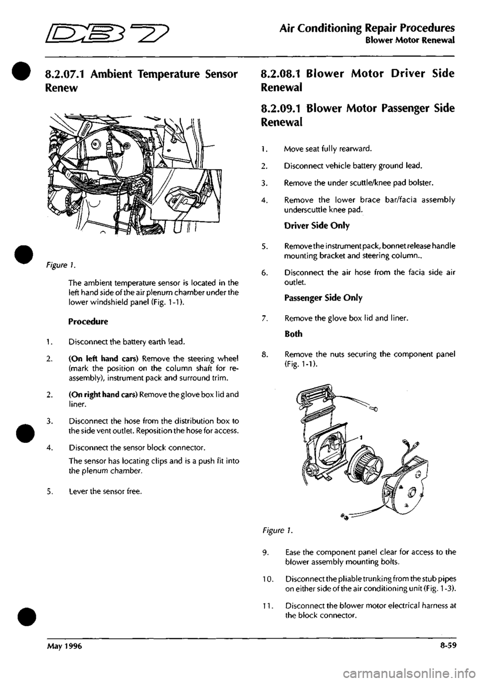
Renew
?\gure
1.
The ambient temperature sensor is located in the
left hand side of the air plenum chamber under the
lower windshield panel (Fig. 1-1).
Procedure
1.
Disconnect the battery earth
lead.
2.
(On left hand cars) Remove the steering wheel
(mark the position on the column shaft for re
assembly), instrument pack and surround
trim.
2.
(On right hand cars) Removethegloveboxlidand
liner.
3. Disconnect the hose from the distribution box to
the side vent outlet. Reposition the hose for access.
4.
Disconnect the sensor block connector.
The sensor has locating clips and is a push fit into
the plenum chamber.
5. Lever the sensor free.
8.2.08.1 Blower Motor Driver Side
Renewal
8.2.09.1 Blower Motor Passenger Side
Renewal
1.
Move seat
fu 1
ly rearward.
2.
Disconnect vehicle battery ground
lead.
3. Remove the under scuttle/knee pad bolster.
4.
Remove the lower brace bar/facia assembly
underscuttle knee pad.
Driver Side Only
5. Removetheinstrumentpack, bonnetreieasehandle
mounting bracket and steering column..
6. Disconnect the air hose from the facia side air
outlet.
Passenger Side Only
7. Remove the glove box lid and liner.
Both
8. Remove the nuts securing the component panel
(Fig.
1-1).
Figure 1.
9. Ease the component panel clear for access to the
blower assembly mounting bolts.
10.
Disconnect the pliable trunking from the stub pipes
on either side of the air conditioning unit
(Fig.
1
-3).
11.
Disconnect the blower motor electrical harness at
the block connector.
May 1996 8-59