bonnet ASTON MARTIN DB7 1997 Workshop Manual
[x] Cancel search | Manufacturer: ASTON MARTIN, Model Year: 1997, Model line: DB7, Model: ASTON MARTIN DB7 1997Pages: 421, PDF Size: 9.31 MB
Page 11 of 421
ES^^^?
Electrics
Headlamp Unit / Headlamp Alignment
6.1.01 Headlamp Unit
Procedure
1.
Remove the front apron undertray and remove the
complete nose assembly.
2.
Release the headlamp plug from the body clip and
disconnect the
plug.
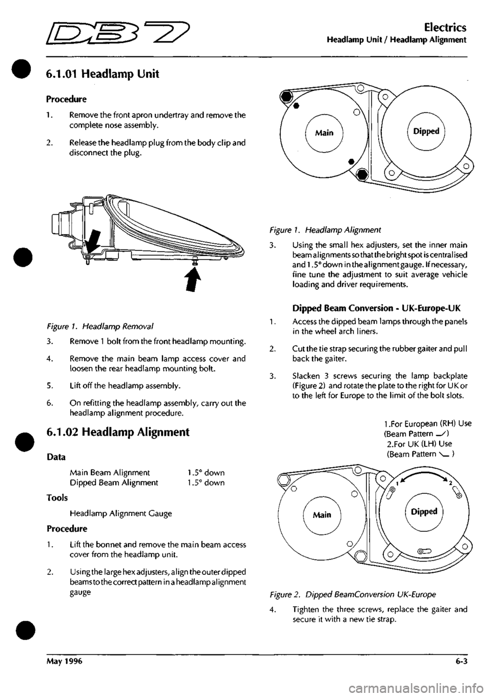
Figure 7. Headlamp Removal
3. Remove
1
bolt from the front headlamp mounting.
4.
Remove the main beam lamp access cover and
loosen the rear headlamp mounting bolt.
5. Lift off the headlamp assembly.
5. On refitting the headlamp assembly, carry out the
headlamp alignment procedure.
6.1.02 Headlamp Alignment
Data
Main Beam Alignment 1.5° down
Dipped Beam Alignment 1.5° down
Tools
Headlamp Alignment Gauge
Procedure
1.
Lift the bonnet and remove the main beam access
cover from the headlamp unit.
2.
Usingthe large hex adjusters, align theouter dipped
beamsto thecorrect pattern in
a
headlampalignment
gauge
Figure 1. Headlamp Alignment
3. Using the small hex adjusters, set the inner main
beam al ignments
so
that the bright spot
is
central ised
and 1.5° down inthealignmentgauge. If necessary,
fine tune the adjustment to suit average vehicle
loading and driver requirements.
Dipped Beam Conversion - UK-Europe-UK
1.
Access the dipped beam lamps through the panels
in the wheel arch liners.
2.
Cut the tie strap securing the rubber gaiter and pull
back the gaiter.
3. Slacken 3 screws securing the lamp backplate
(Figure 2) and rotate the plate to the right for U
K
or
to the left for Europe to the limit of the bolt slots.
1
.For European (RH) Use
(Beam Pattern _/)
2.For UK (LH) Use
(Beam Pattern ^^)
Figure 2. Dipped BeamConversion UK-Europe
4. Tighten the three screws, replace the gaiter and
secure it with a new tie strap.
May 1996 6-3
Page 53 of 421
Nb 61 62
COLOUR
PIN
BR
1
B
2
}
kKk
B6 CI
BONNET SWITCH
80
RC
es
B
S4
RY 97 Sr
98
YP
NO COLOUH 65
UB
66
U
67
B
68
N
69
UW
t>IN
1 ? 3 4
5
i
-
AREA B6 B3-I3 CI B4-i8 B2-I2
HEADLAMP CONTROL MODULE
NO COLOUR
PIN
63
YO 1
64
YP 2
?
Uiti
C6 CI
NO 70 71
?2
COLOUR
PIN YW YB
YP_.
1 2 3
AREA
C6 C6
V.
.,
SPEED CONTROL
W»
VALVE SPEED CONTROL
PUW
84 N 84-18 85 H eiJi
I BATTERY POST
|
SPL
15
SPL
16
I
i 1 I
rUSEBOX
NO
COLOW
73
R
39
RO
74
N
53
NY
75
UW
34
UW
76
UW
9
UW
77
RS
78
RS
79
RG
80
RC
81
UR
33
UR
82
UR
8
UR
83
WK
6
LG
PIN 1 2 J
4 6 6 7 8
9 10 II 12 13 14 15 16
1/
IS 19 20 21
li
AREA
B3-15
CI
B4-I8
CI
B2-I2
Bl
B2-I2
Bl B6 Dl B6 Dl
B2-I0
61
B2-I0
Bl Be Bl
1 II
^0
D
("
c
D
Q
00=^ Q
D
0
Q
Q
0
Q
Q
QOZ
Q
0
G
G
NO COLOUF 90 GR 14 WU 17 GW 77 RS 83 DM 91 W 92 NR 93 R 61 BR 94 RY 95 U 79 RG 65 UB 87 YR 46 NB 86 BK 4 NP 5 YS
PIN 1 ? 3 4 5 6 7 8 9 10 II 12 13 14 15 16 17
,1?,
,
AREA B4-I6 Bl Bl 03 03 B2-II 83-14 83-15 Al 01 83-13 D3 A2 04 CI 04 Bl Bl
SHEET
8
AREA
Al
.S
^
(•
QQl 0
Gl,
0
G
Qcm
G
0
G
0
G
0
NO COLOUR 96
UW
97
CY
98
YP
70
YW
71
YB
51
RO
15
RO
99
UR
63
YO
50
BR
P»i 1
2 3
4 5 6 7
8 9 10
II 12 1?
AREA 82-12
Dl
01 A3 A3 CI 81
82-10
A2 CI
'LH SIDE REPEATER'
fcRUISE
CONTROL!
CLUTCH
SWITCH
NO COLOUR AREA 88
B Dl
99
{R
E±J1
NO COLOUR AREA 86 BK 86 67 YR B6
^27 Wiring Diagram
Model
-
Aston Martin
DB7
Coupe
Harness Title
-
Left Forward
2
Drawing Part No.
-
B37-81297
Revision
- 0
Sheet
2 of 29
-
Up to 97 MY
Page 108 of 421
^7
Electrics
Component Index Sheet 1-97 MY
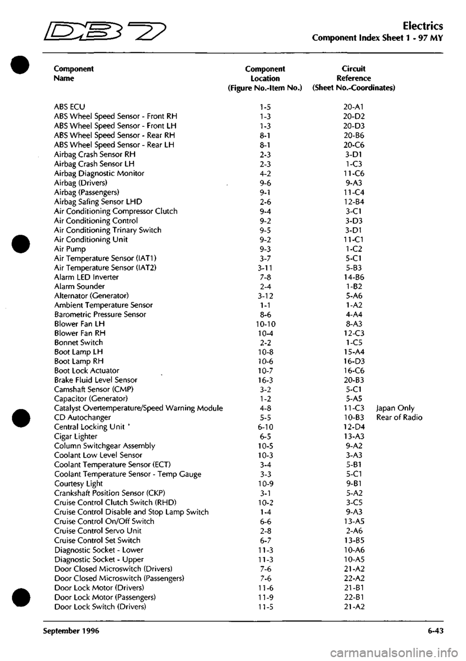
Component
Name
ABS ECU
ABS Wheel Speed Sensor - Front RH
ABS Wheel Speed Sensor - Front LH
ABS Wheel Speed Sensor - Rear RH
ABS Wheel Speed Sensor - Rear LH
Airbag Crash Sensor RH
Airbag Crash Sensor LH
Airbag Diagnostic Monitor
Airbag (Drivers)
Airbag (Passengers)
Airbag Safing Sensor LHD
Air Conditioning Compressor Clutch
Air Conditioning Control
Air Conditioning Trinary Switch
Air Conditioning Unit
Air Pump
Air Temperature Sensor (IAT1)
Air Temperature Sensor (IAT2)
Alarm LED Inverter
Alarm Sounder
Alternator (Generator)
Ambient Temperature Sensor
Barometric Pressure Sensor
Blower Fan LH
Blower Fan RH
Bonnet Switch
Boot Lamp LH
Boot Lamp RH
Boot Lock Actuator
Brake Fluid Level Sensor
Camshaft Sensor (CMP)
Capacitor (Generator)
Catalyst Overtemperature/Speed Warning Module
CD Autochanger
Central Locking Unit '
Cigar Lighter
Column Switchgear Assembly
Coolant Low Level Sensor
Coolant Temperature Sensor (ECT)
Coolant Temperature Sensor - Temp Gauge
Courtesy Light
Crankshaft Position Sensor (CKP)
Cruise Control Clutch Switch (RHD)
Cruise Control Disable and Stop Lamp Switch
Cruise Control On/Off Switch
Cruise Control Servo Unit
Cruise Control Set Switch
Diagnostic Socket - Lower
Diagnostic Socket - Upper
Door Closed Microswitch (Drivers)
Door Closed Microswitch (Passengers)
Door Lock Motor (Drivers)
Door Lock Motor (Passengers)
Door Lock Switch (Drivers)
Component
Location
(Figure No.-ltem No.)
1-5
1-3
1-3
8-1
8-1
2-3
2-3
4-2
9-6
9-1
2-6
9-4
9-2
9-5
9-2
9-3
3-7
3-11
7-8
2-4
3-12
1-1
8-6
10-10
10-4
2-2
10-8
10-6
10-7
16-3
3-2
1-2
4-8
5-5
6-10
6-5
10-5
10-3
3-4
3-3
10-9
3-1
10-2
1-4
6-6
2-8
6-7
11-3
11-3
7-6
7-6
11-6
11-9
11-5
Circuit
Reference
(Sheet No.-Coordinates)
20-A1
20-D2
20-D3
20-B6
20-C6
3-D1
1-C3
11-C6
9-A3
11-C4
12-B4
3-C1
3-D3
3-D1
11-CI
1-C2
5-C1
5-B3
14-B6
1-B2
5-A6
1-A2
4-A4
8-A3
12-C3
1-C5
15-A4
16-D3
16-C6
20-B3
5-C1
5-A5
11-C3 Japan Only
10-B3 Rear of Radio
12-D4
13-A3
9-A2
3-A3
5-B1
5-C1
9-B1
5-A2
3-C5
9-A3
13-A5
2-A6
13-B5
10-A6
10-A5
21-A2
22-A2
21-B1
22-Bl
21-A2
September 1996 6-43
Page 192 of 421
Electrics
Airbag System ^^?
7.8.02.6
Renew
Passenger's Airbag Module
Read and adhere to all warnings and safety
procedures quoted at the start of this section when
working on airbag modules.
Disconnect the battery and wait for at least one
minute before proceeding with the airbag removal.
Note:
The
vehicle battery
must
be disconnected within
12
seconds
of switchingoff
the
ignition
to
avoid the alarm
siren sounding.
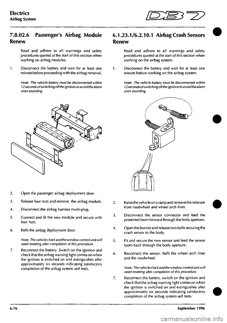
2. Open the passenger airbag deployment door.
3. Release four nuts and remove the airbag module.
4.
Disconnect the airbag harness multi-plug.
5. Connect and fit the new module and secure with
four nuts.
6. Refit the airbag deployment door.
Note:
The vehicle
clock and
the
window control unit will
need
resetting
after completion of
this
procedure.
7. Reconnect the battery. Switch on the ignition and
check that the airbag warning
I
ight comes on when
the ignition is switched on and extinguishes after
approximately six seconds indicating satisfactory
completion of the airbag system self tests.
6.1.23.1/6.2.10.1 Airbag
Crash
Sensors
Renew
Read and adhere to all warnings and safety
procedures quoted at the start of this section when
working on the airbag system.
1.
Disconnect the battery and wait for at least one
minute before working on the airbag system.
Note: The vehicle
battery
must be disconnected within
12
seconds
of switchingoff
the
ignition
to
avoid thealarm
siren sounding.
4.
5.
Raisethevehicleon a rampand remove the relevant
front roadwheel and wheel arch liner.
Disconnect the sensor connector and feed the
protected loom forward through the body aperture.
Open the bonnet and release two bolts securing the
crash sensor to the body.
Fit and secure the new sensor and feed the sensor
loom back through the body aperture.
Reconnect the sensor. Refit the wheel arch liner
and the roadwheel.
Note:
The vehicle
clock and
the
window control unit will
need
resetting
after completion of
this
procedure.
Reconnect the battery, switch on the ignition and
check that the airbag warning
I
ight comes on when
the ignition is switched on and extinguishes after
approximately six seconds indicating satisfactory
completion of the airbag system self tests.
6-76 September 1996
Page 194 of 421
Electrics
Airbag System '=2?
Airbag System Diagnostics
System Description
The airbag system installation comprises:
Airbag Diagnostic Module
Driver and passenger airbag modules
Two front impact (crash) sensors
One 'safing' sensor
Dedicated wiring harness
SRS indicator/warning lamp
The system is designed to provide protection for
both driver and front seat passenger by automatical ly
deploying airbags in the event of
a
collision during
forward travel.
In the event of a collision, the crash and safing
sensors will operate, completing the firing circuit
and causing the airbags to inflate within 32
milliseconds. At least one crash sensor and the
safing sensor must operate to fire the airbags.
Any faults in system components, installation or
wiring will be indicated by a flashing code on the
SRS/AIRBAG warning lamp. Fault code information
may also be monitored using the PDU or scan
tool.
Component Descriptions
Airbag Diagnostic Module
The airbag diagnostic module is mounted on top of
the passenger airbag mountingcage.Thediagnostic
module contains the microprocessor which is
connected to the complete airbag system. The state
of the three system sensors, the two airbag modules
and the wiring harness is constantly monitored by
the microprocessor for faults and for sensor
activation (crash) conditions.
The diagnostic module also confirms correct supply
voltage by comparing
a
direct battery voltage input
with a similar input via the ignition switch.
The diagnostic module contains a reserve power
supply, enabling the airbags to fire even if the
supply voltage is lost due to collision damage. The
reserve power charge will be retained for
approximately one minute if the positive battery
supply is lost in a collision. An auxiliary internal
circuit known as the 'dwell enhancer' provides a
temporary ground if normal system ground was lost
in a collision.
Wiring Harness
A dedicated electrical wiring harness is used to
connect all system components to the bulkhead
harness. To allow free movement of the steering
mechanism, a cable reel cassette is used to connect
the drivers airbag in the steering wheel to the airbag
harness on the steering column.
Airbag Modules
The two airbag modules contain achargeof sodium
azide/copper oxide which wi
11
generate
a
sufficient
volume of nitrogen gas to fully inflate the airbag
when ignited by an electrical impulse. The volume
of gas is greater in the passenger side airbag due to
its larger size.
Both airbag modules, including the surrounding
trim of the drivers airbag, are non-serviceable and
once deployed, must be renewed as a complete
assembly.
Crash and Safing Sensors
The two crash sensors are mounted one at either
side of the bumper mounting cross member, outside
of the bonnet hinges.
The safing sensor is mounted in the base of the
drivers side 'A' post.
The two crash sensors and the safing sensor
determine when airbag deployment is necessary in
a crash condition.
The sensor contacts will only close when the vehicle
suffers a forward impact of sufficient force. At least
one crash sensor and the safing sensor contacts
must close before the airbags will deploy. The
doubletrigger strategy
is
used to prevent deployment
during trivial impacts such as contacts during
parking.
6-78 September 1996
Page 311 of 421
Air Conditioning
Refrigeration /s:s^°27
Refrigeration
Safety Precautions
The air conditioning system is designed to use only
Refrigerant E134A (dichlorodifluoromethane). Extreme
care must betaken NOT to use
a
methylchloride refrigerant.
The chemical reaction between methylchloride and the
aluminium parts ofthe compressor results in the formation
ofproductswhich burn spontaneously on exposure toair,
or decompose with violence in the presence of moisture.
The suitable refrigerant is supplied under the following
names.
El 34A KLEA or equivalent
Warning: Take care when handling refrigerant. Serious
damage will occur if it is allowed to come into
contact with the eyes. Always wear with goggles
and gloves when working with refrigerant
First Aid
If refrigerant should come into contact with the
eyes or
skin,
splash the eyes or affected area with
cold water for several minutes. DO NOT RUB. As
soon as possible thereafter, obtain treatment from a
Doctor or an eye specialist.
Good Practice
1.
Protective sealing plugs must be fitted to all
disconnected pipes and units.
2.
Theprotectivesealingpiugsmustremain inposition
on ail replacement components and pipes until
immediately before assembly.
3. Any part arriving for assembly without sealing
plugs in position must be returned to the supplier as
defective.
4.
It is essential that a second backing spanner is
always used when tightening or loosening all joints.
This minimises distortion or strain on components
or connecting hoses.
5. Components must not be lifted by connecting
pipes,
hoses or capillary tubes.
6. Care must be taken not to damage fins on the
condenser or evaporator matrices. Any damage
must be rectified by the use of fin combs.
7. Before assembly oftube and hosejoints, use
a
small
amount of clean new refrigerant oil on the sealing
seat.
8. Refrigerant oil for any purpose must be kept very
clean and capped at all times. This prevents the oil
absorbing moisture.
9. Before assembly the condition of joints and flares
must be examined. Dirt and even minor damage
will cause leaks at the high pressure points
encountered in the system.
10.
Dirty end fitting can only be cleaned using a cloth
wetted with alcohol.
11.
Afterremovingsealingplugsand immediatelybefore
assembly, visually check the bore of pipes and
components. Where any dirt or moisture is
discovered,
the part must be rejected.
12. Ail components must be allowed to reach room
temperature before sealing plugs are removed.
This prevents condensation should the component
be cold initially.
13.
Before finally tightening hose connections ensure
that the hose lies in the correct position, is not
kinked or twisted and will not be trapped by
subsequent operations, e.g., refitting or closing
bonnet.
14.
Check that hoses are correctly fitted in clips or
straps.
15.
The compressor must be stored horizontally with
the sump down. It must not be rotated before fitting
and charging. Do not remove the shipping plate
until immediately before assembly. Always use
new "O" ring seals in those joints that incorporate
them.
"O" ring seals should be coated with
compressor oil before fitting.
16.
Components or hoses removed must be sealed
immediately after removal.
1 7. Afterthe system has been opened the receiver-drier
must be renewed.
18.
Before
testing,
run the engine until normal running
temperature is reached. This ensures that sufficient
vacuum is available for test. For cooling tests the
engine must be running for the compressor clutch
to operate.
8-34 May 1996
Page 328 of 421
^?
Air Conditioning Repair Procedures
Compressor Removal
8.1.01.1 Compressor Removal/Renewal
Procedure
1.
Open the bonnet and fit a wing cover.
2.
Depressurise the air conditioning system.
3.
6.
7.
8.
9.
Disconnect the low and high pressure hoses from
the rear of the compressor. Plug the hose ends to
prevent the ingress of dirt.
Remove the compressor pivot bolt securing nut.
Carefully separate the muffler from the compressor
and remove and discard the 'O' ring
seal.
Fit a blanking plug to the muffler and a blanking
plate to the compressor, fit and tighten the bolt that
secures blanking plate.
Raise the vehicle to working height on a ramp.
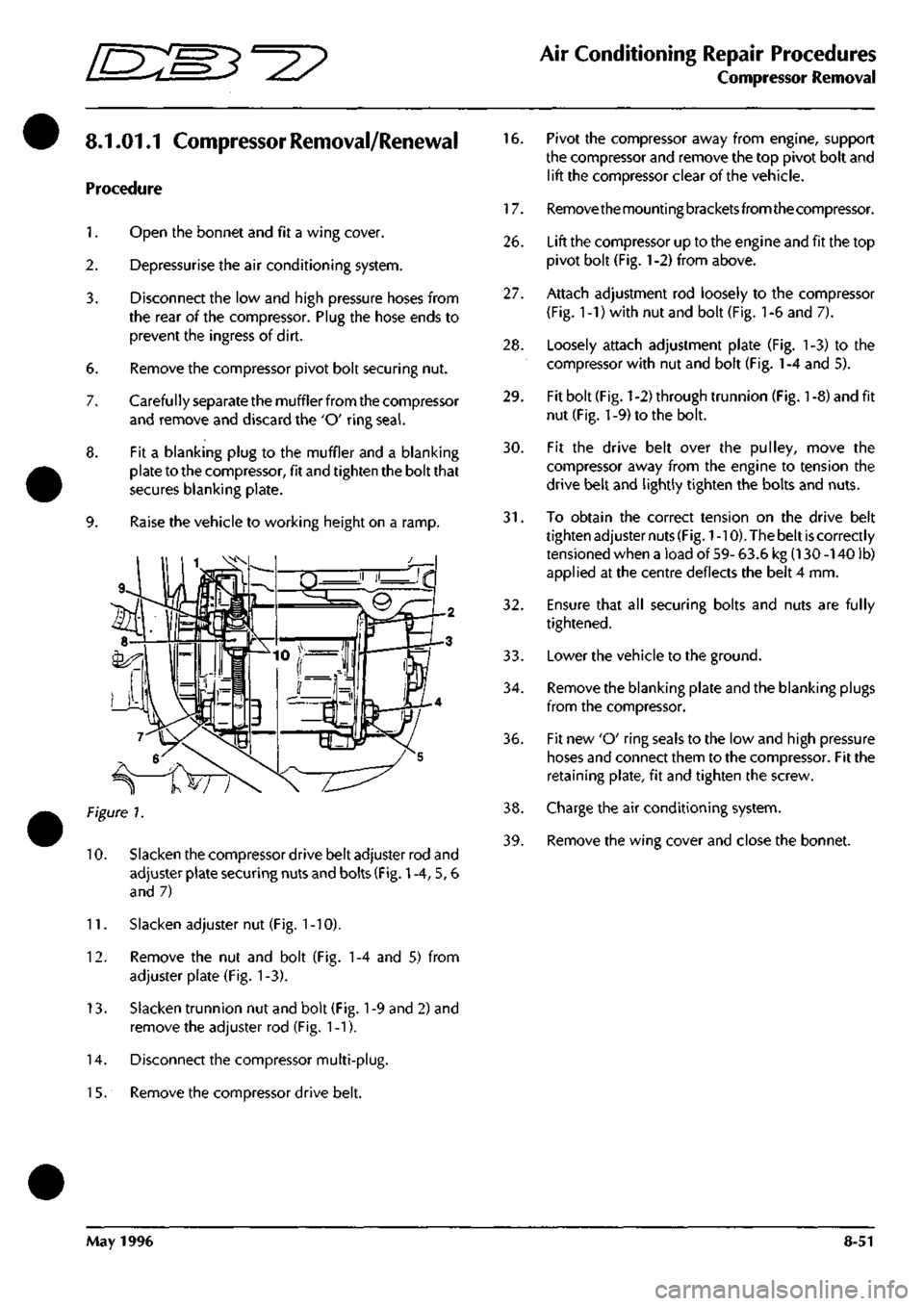
Figure 7.
10.
Slacken the compressor drive belt adjuster rod and
adjuster plate securing nuts and bolts (Fig.
1
-4, 5, 6
and 7)
11.
Slacken adjuster nut (Fig.
1
-10).
12.
Remove the nut and bolt (Fig. 1-4 and 5) from
adjuster plate (Fig. 1-3).
13.
Slacken trunnion nut and bolt (Fig.
1
-9 and 2) and
remove the adjuster rod (Fig. 1-1).
14.
Disconnect the compressor multi-plug.
1
5. Remove the compressor drive belt.
16.
Pivot the compressor away from engine, support
the compressor and remove the top pivot bolt and
lift the compressor clear of the vehicle.
17.
Removethemountingbracketsfromthecompressor.
26.
Lift the compressor up to the engine and fit the top
pivot bolt (Fig.
1
-2) from above.
27.
Attach adjustment rod loosely to the compressor
(Fig.
1
-1) with nut and bolt (Fig.
1
-6 and 7).
28.
Loosely attach adjustment plate (Fig. 1-3) to the
compressor with nut and bolt (Fig.
1
-4 and 5).
29.
Fit bolt (Fig.
1
-2) through trunnion (Fig.
1
-8) and fit
nut (Fig. 1-9) to the bolt.
30.
Fit the drive belt over the pulley, move the
compressor away from the engine to tension the
drive belt and lightly tighten the bolts and nuts.
31.
To obtain the correct tension on the drive belt
tighten adjuster nuts
(Fig.
1
-10). The belt
is
correctly
tensioned when a load of 59- 63.6 kg (130 -140 lb)
applied at the centre deflects the belt 4 mm.
32.
Ensure that all securing bolts and nuts are fully
tightened.
33.
Lowerthe vehicle to the ground.
34.
Remove the blanking plate and the blanking plugs
from the compressor.
36.
Fit new 'O' ring seals to the low and high pressure
hoses and connect them to the compressor. Fit the
retaining plate, fit and tighten the screw.
38.
Charge the air conditioning system.
39.
Remove the wing cover and close the bonnet.
May 1996 8-51
Page 329 of 421
Air Conditioning Repair Procedures
Field Coil Renewal
/
Gasket Kit Renewal ffi^e^'^^
8.1.02.1 Field Coil Renewal 8.1.03.1 Renew Gasket
Kit
Procedure
1.
Open
the
bonnet
and fit a
wing cover.
2.
Depressurise
the air
conditioning system.
3. Remove
the
compressor.
4.
Remove
the
compressor drive clutch.
5. Remove
the
compressor pulley.
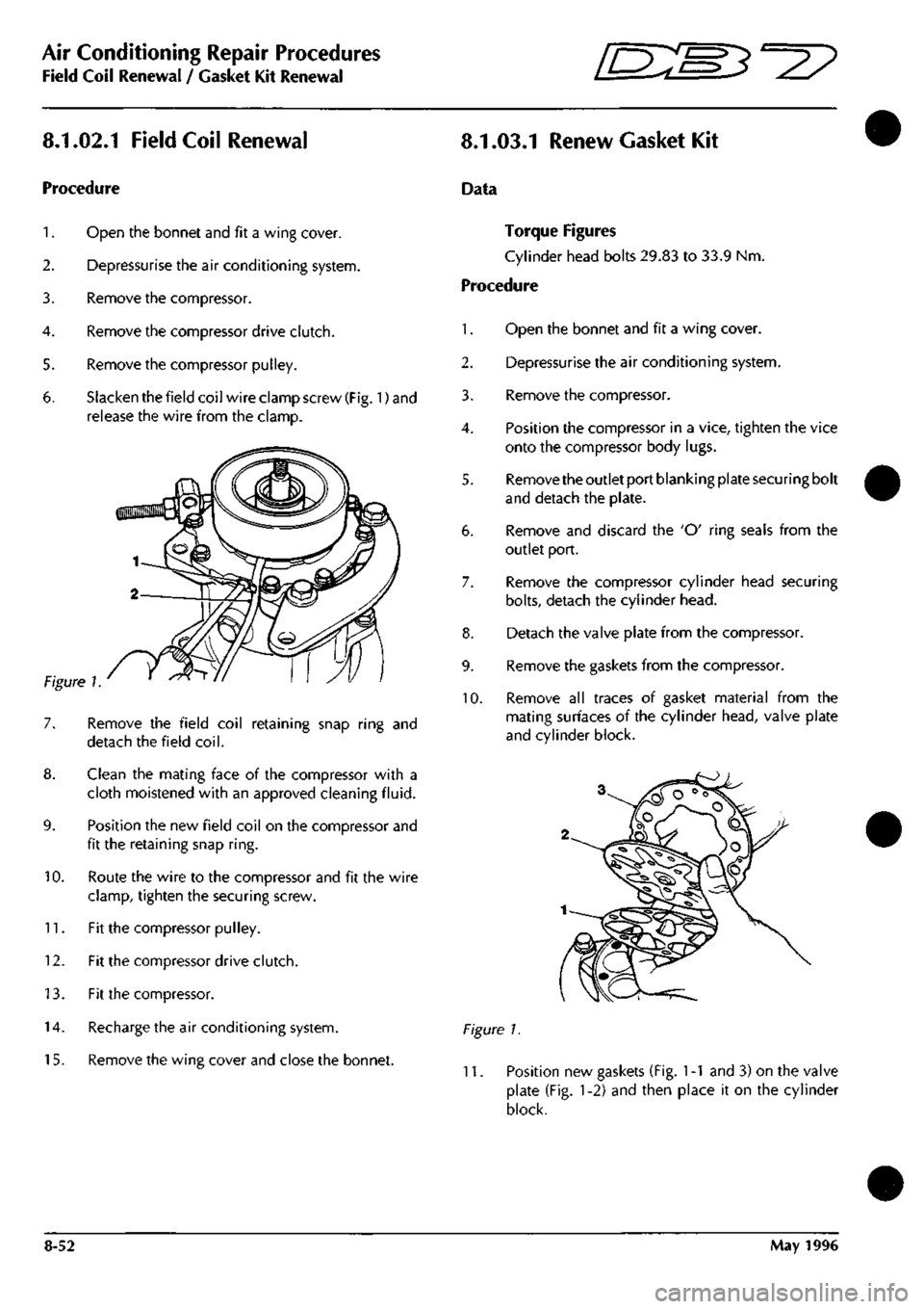
6. Slacken
the
field coil wire clamp screw
(Fig.
1) and
release
the
wire from
the
clamp.
10.
Remove
the
field coil retaining snap ring
and
detach
the
field
coil.
Clean
the
mating face
of the
compressor with
a
cloth moistened with
an
approved cleaning
fluid.
Position
the new
field coil
on the
compressor
and
fit
the
retaining snap
ring.
Route
the
wire
to the
compressor
and fit the
wire
clamp, tighten
the
securing screw.
11.
Fit the
compressor pulley.
12.
Fit the
compressor drive clutch.
13.
Fit the
compressor.
14.
Recharge
the air
conditioning system.
15.
Remove
the
wing cover
and
close
the
bonnet.
Data
Torque Figures
Cylinder head bolts 29.83
to 33.9 Nm.
Procedure
1.
Open
the
bonnet
and fit a
wing cover.
2.
Depressurise
the air
conditioning system.
3. Remove
the
compressor.
4.
Position
the
compressor
in a
vice, tighten
the
vice
onto
the
compressor body lugs.
5. Remove the outlet port blanking plate securing bolt
and detach
the
plate.
6. Remove
and
discard
the 'O'
ring seals from
the
outlet port.
7. Remove
the
compressor cylinder head securing
bolts,
detach
the
cylinder head.
8. Detach
the
valve plate from
the
compressor.
9. Remove
the
gaskets from
the
compressor.
10.
Remove
all
traces
of
gasket material from
the
mating surfaces
of the
cylinder head, valve plate
and cylinder block.
Figure
1.
11.
Position
new
gaskets (Fig.
1 -1
and 3) on the
valve
plate
(Fig. 1-2) and
then place
it on the
cylinder
block.
8-52 May
1996
Page 330 of 421
ES3^^
Air Conditioning Repair Procedures
Valve Plate Renewal
Figure
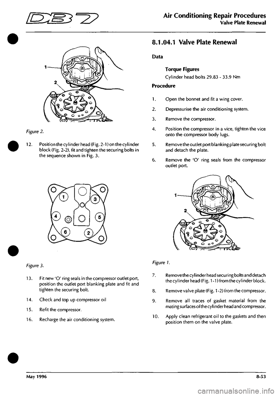
2.
12.
Position the cylinder head (Fig. 2-1) on the cylinder
block (Fig. 2-2), fit and tighten the securing bolts in
the sequence shown in Fig. 3.
8.1.04.1 Valve Plate Renewal
Data
Torque Figures
Cylinder head bolts 29.83 - 33.9 Nm
Procedure
1.
Open the bonnet and fit a wing cover.
2.
Depressurise the air conditioning system.
3. Remove the compressor.
4.
Position the compressor in a vice, tighten the vice
onto the compressor body lugs.
5. Remove the outlet port blanking plate securing bolt
and detach the plate.
6. Remove the 'O' ring seals from the compressor
outlet port.
figure 3.
13.
Fit new 'O' ring seals in the compressor outlet port,
position the outlet port blanking plate and fit and
tighten the securing bolt.
14.
Check and top up compressor oil
15.
Refit the compressor.
16.
Recharge the air conditioning system.
Figure 1.
7. Removethecylinder head securing boltsand detach
the cylinder head (Fig. 1-1) from the cylinder block.
8. Remove valve plate
(Fig.
1
-2) from the compressor.
9. Remove all traces of gasket material from the
mati
ng
surfaces of the cy
I
i nder
head
and compressor.
10.
Apply clean refrigerant oil to the gaskets and then
position them on the valve plate.
May 1996 8-53
Page 331 of 421
Air Conditioning Repair Procedures
Expansion Valve Renewal
ES^'^?
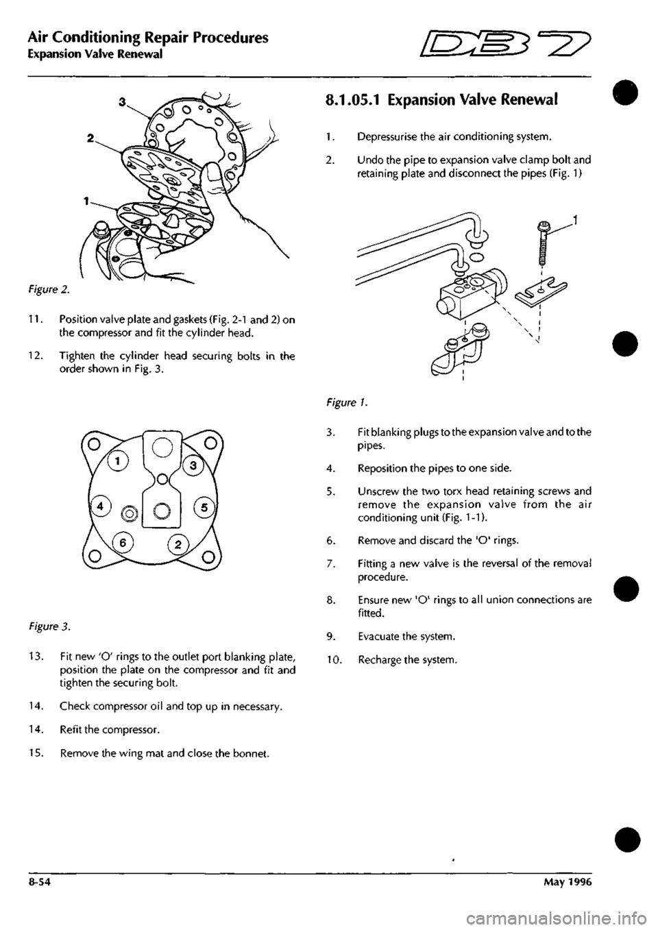
Figure 2.
11.
Position valve plate and gaskets (Fig. 2-1 and 2) on
the compressor and fit the cylinder head.
12.
Tighten the cylinder head securing bolts in the
order shown in Fig. 3.
Figure 3.
13.
Fit new 'O' rings to the outlet port blanking plate,
position the plate on the compressor and fit and
tighten the securing bolt.
14.
Check compressor oil and top up in necessary.
14.
Refit the compressor.
15.
Remove the wing mat and close the bonnet.
8.1.05.1 Expansion Valve Renewal
1.
Depressurise the air conditioning system.
2.
Undo the pipe to expansion valve clamp bolt and
retaining plate and disconnect the pipes (Fig. 1)
Figure 1.
3. Fit blanking plugs to the expansion valve and to the
pipes.
4.
Reposition the pipes to one side.
5. Unscrew the two torx head retaining screws and
remove the expansion valve from the air
conditioning unit (Fig.
1
-1).
6. Remove and discard the 'O' rings.
7. Fitting a new valve is the reversal of the removal
procedure.
8. Ensure new 'O' rings to all union connections are
fitted.
9. Evacuate the system.
10.
Recharge the system.
8-54 May 1996